EP0876950B1 - Power assisted steering for motor vehicles - Google Patents
Power assisted steering for motor vehicles Download PDFInfo
- Publication number
- EP0876950B1 EP0876950B1 EP98107913A EP98107913A EP0876950B1 EP 0876950 B1 EP0876950 B1 EP 0876950B1 EP 98107913 A EP98107913 A EP 98107913A EP 98107913 A EP98107913 A EP 98107913A EP 0876950 B1 EP0876950 B1 EP 0876950B1
- Authority
- EP
- European Patent Office
- Prior art keywords
- steering
- power
- assisted
- motor vehicles
- vehicle
- Prior art date
- Legal status (The legal status is an assumption and is not a legal conclusion. Google has not performed a legal analysis and makes no representation as to the accuracy of the status listed.)
- Expired - Lifetime
Links
Images
Classifications
-
- B—PERFORMING OPERATIONS; TRANSPORTING
- B62—LAND VEHICLES FOR TRAVELLING OTHERWISE THAN ON RAILS
- B62D—MOTOR VEHICLES; TRAILERS
- B62D5/00—Power-assisted or power-driven steering
- B62D5/06—Power-assisted or power-driven steering fluid, i.e. using a pressurised fluid for most or all the force required for steering a vehicle
Definitions
- the invention relates to power steering for Motor vehicles, especially for commercial vehicles, according to the Preamble of claim 1.
- Such an auxiliary steering contains at least two separate auxiliary circuits, at least the first of which has a servo motor a displaceable by the force of a hydraulic pressure medium Contains pistons.
- a control valve is used for Controlling the hydraulic pressure medium to and from the work rooms of the servo motor.
- a steering gear is used for Convert a rotary motion of a steering shaft into a back and forth movement of the piston.
- One with a steering handwheel Steering spindle is provided via a torsion spring connected to an input member of the steering gear.
- On The output link of the steering gear is with wheels to be steered connected to the motor vehicle.
- Such power steering is known from the DE 29 18 975 C2.
- This power steering system has two hydraulic separate auxiliary circles.
- the steering gear this power steering builds in the axial direction relatively long because two control valves of the two auxiliary circuits are arranged side by side on the steering spindle. Hydraulic support for resetting the steering gear and the wheels to be steered after releasing them the steering handwheel after a steering operation is in this Power steering is not provided.
- the invention has for its object in a Power steering according to the preamble of claim 1 Shorten steering gear towards its steering spindle.
- This object is characterized by that in claim 1 Power steering solved in that at the Steering spindle at least one sensor for detecting an angle of rotation and / or a torque is arranged. Moreover is at least one sensor for detecting a steering angle on an input or an output member of the Steering gear arranged. With the help of these sensors the size and direction of the hydraulic assist system in the second auxiliary circle through a common, electronically controlled solenoid valve controlled. This allows the second control valve on the steering spindle omitted. The sensor located there is shorter than the second control valve.
- the electromagnetic valve hydraulic support for resetting the steering gear and the wheels to be steered after releasing the Steering handwheel controls after a steering operation.
- a parameter device is provided for influencing the auxiliary support of the two auxiliary groups via an electronics unit depending on at least a parameter, such as vehicle speed, Steering speed, yaw rate, loading of the vehicle, and others.
- a parameter such as vehicle speed, Steering speed, yaw rate, loading of the vehicle, and others.
- the invention is based on the example of a ball nut power steering explained. With the same effect However, the invention also applies to power assisted rack and pinion steering be applied.
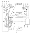
- a steering gear 2 contains one Working piston 3, the row of balls 4 with a Threaded spindle 5 and a toothing 6 with a segment shaft 7 is operatively connected.
- the threaded spindle forms 5 an input member of the steering gear 2 and the segment shaft 7 is an output member of the steering gear 2.
- a steering column arm from the segment shaft 7 8 and a steering linkage 10 connect at least two wheels 11 of the motor vehicle to be steered.
- the threaded spindle 5 as the input member of the steering gear 2 is via a torsion spring 14 with a steering spindle 15 connected, which carries a steering handwheel 16.
- the steering spindle 15 can be divided by a universal joint 17.
- the two working rooms 12 and 13 are via a control valve 18 acted upon by pressure medium, which is a servo pump 19 promotes from a container 20.
- the servo pump 19 is, for example, by a vehicle engine 21 or a Electric motor driven.
- the control valve 18 is in the embodiment as Open center valve. However, it can also be carried out with a closed center, whereby additionally to the servo pump 19, a pressure medium reservoir, not shown must be present.
- Flow indicator 23 installed in a pressure line 22 from the servo pump 19 to leads the control valve 18, is in a known manner Flow indicator 23 installed. Via the flow indicator 23, the driver of the motor vehicle can errors in the pressure medium supply are reported become.
- a second auxiliary circuit 24 contains an electromagnetic valve 25, for example a proportional valve, the is regulated by an electronics unit 26.
- the electronics unit 26 receives signals from at least a first one Sensor 27 for detecting a steering angle and / or one Torque, which is arranged on the steering shaft 15.
- a second sensor 28 for detecting a steering angle is on the output member, the segment shaft 7, the steering gear 2 arranged and delivers the appropriate signals to the Electronics unit 26.
- the sensor can have the same effect also arranged on the input member of the steering gear 2 his.
- Solenoid valve 25 are pressurized, that promotes a servo pump 31 from a container 32.
- the Servo pump 31 is operated, for example, by an electric motor 33 or driven by the wheels 11 of the motor vehicle.
- the solenoid valve 25 In the embodiment is the solenoid valve 25 with open center. In a closed system In addition to the servo pump 31, the middle does not become a shown pressure medium storage required. Between the Servo pump 31 and solenoid valve 25 is also in a flow indicator 34 to the second auxiliary circuit 24 corresponding to the flow indicator 23 of the first auxiliary circuit used.
- the additional function of hydraulic support of the Resetting the steering gear 2 and the wheels to be steered 11 after releasing the steering handwheel 16 after a Steering is possible as follows: Because the requirement there is that the steered wheels without operating the steering wheel the control valve turns 18 of the first auxiliary circuit via the torsion spring 14 in its neutral position. This recognizes the position Electronics unit 26, since there is no relative rotation of the sensors 27 and 28 on the steering shaft 15 and on the Segment wave 7 exists. From this state and the information of the second sensor 28 on the steering shaft 7 (size and Direction of the steering shaft rotation) the electronics unit 26 calculate the corresponding control command, the the steered wheels 11 with the help of the servo motor 30 exactly leads back to the straight-ahead position.
- Both the sensors 27 and 28 and the Electronics unit 26 are designed redundantly. Thereby errors in the steering system can be recognized and corrected.
- the second hydraulic circuit 24 has a narrower valve characteristic, d. H. smaller control paths of the solenoid valve 25, then you can via a parameter device the auxiliary support of the two auxiliary groups via the electronics unit 26 depending on influence at least one parameter.
- Such parameters can be, for example, the driving speed of the Vehicle, the steering speed, the yaw rate, the loading of the vehicle and others.
Description
Die Erfindung betrifft eine Hilfskraftlenkung für
Kraftfahrzeuge, insbesondere für Nutzfahrzeuge, nach dem
Oberbegriff des Anspruches 1. Eine solche Hilfskraftlenkung
enthält wenigstens zwei voneinander getrennte Hilfskraftkreise,
von denen wenigstens der erste einen Servomotor mit
einem durch die Kraft eines hydraulischen Druckmittels verschiebbaren
Kolben enthält. Ein Steuerventil dient zum
Steuern des hydraulischen Druckmittels zu und von den Arbeitsräumen
des Servomotors. Ein Lenkgetriebe dient zum
Umwandeln einer Drehbewegung einer Lenkspindel in eine hin-und
hergehende Bewegung des Kolbens. Eine mit einem Lenkhandrad
versehene Lenkspindel ist über eine Torsionsfeder
mit einem Eingangsglied des Lenkgetriebes verbunden. Ein
Ausgangsglied des Lenkgetriebes ist mit zu lenkenden Rädern
des Kraftfahrzeugs verbunden.The invention relates to power steering for
Motor vehicles, especially for commercial vehicles, according to the
Preamble of
Eine derartige Hilfskraftlenkung ist bekannt aus der DE 29 18 975 C2. Diese Hilfskraftlenkung weist zwei hydraulisch voneinander getrennte Hilfskraftkreise auf. Das Lenkgetriebe dieser Hilfskraftlenkung baut in Axialrichtung relativ lang, da zwei Steuerventile der beiden Hilfskraftkreise an der Lenkspindel nebeneinander angeordnet sind. Eine hydraulische Unterstützung der Rückstellung des Lenkgetriebes und der zu lenkenden Räder nach einem Loslassen des Lenkhandrades nach einem Lenkvorgang ist bei dieser Hilfskraftlenkung nicht vorgesehen.Such power steering is known from the DE 29 18 975 C2. This power steering system has two hydraulic separate auxiliary circles. The steering gear this power steering builds in the axial direction relatively long because two control valves of the two auxiliary circuits are arranged side by side on the steering spindle. Hydraulic support for resetting the steering gear and the wheels to be steered after releasing them the steering handwheel after a steering operation is in this Power steering is not provided.
Der Erfindung liegt die Aufgabe zugrunde, bei einer
Hilfskraftlenkung nach dem Oberbegriff des Anspruches 1 das
Lenkgetriebe in Richtung seiner Lenkspindel zu verkürzen. The invention has for its object in a
Power steering according to the preamble of
Diese Aufgabe wird durch die im Anspruch 1 gekennzeichnete
Hilfskraftlenkung dadurch gelöst, daß an der
Lenkspindel wenigstens ein Sensor zum Erfassen eines Drehwinkels
und/oder eines Drehmomentes angeordnet ist. Außerdem
ist wenigstens ein Sensor zum Erfassen eines Lenkwinkels
an einem Eingangs- oder an einem Ausgangsglied des
Lenkgetriebes angeordnet. Mit Hilfe dieser Sensoren werden
die Größe und die Richtung der hydraulischen Hilfskraftunterstützung
in dem zweiten Hilfskraftkreis über ein gemeinsames,
elektronisch gesteuertes Elektromagnetventil gesteuert.
Dadurch kann das zweite Steuerventil an der Lenkspindel
entfallen. Der dort angeordnete Sensor baut kürzer als
das zweite Steuerventil.This object is characterized by that in
Vorteilhafte und zweckmäßige Ausgestaltungen der Erfindung sind in den Unteransprüchen angegeben. Dazu ist insbesondere vorgesehen, daß das Elektromagnetventil die hydraulische Unterstützung zur Rückstellung des Lenkgetriebes und der zu lenkenden Räder nach einem Loslassen des Lenkhandrades nach einem Lenkvorgang steuert. Außerdem ist eine Parameter-Einrichtung vorgesehen für eine Beeinflussung der Hilfskraftunterstützung der beiden Hilfskraftkreise über eine Elektronik-Einheit in Abhängigkeit von wenigstens einem Parameter, wie Fahrgeschwindigkeit des Fahrzeugs, Lenkgeschwindigkeit, Giergeschwindigkeit, Beladung des Fahrzeugs, und anderen. Zur Steuerung der Parameter-Einrichtung ist es besonders vorteilhaft, wenn der zweite Hilfskraftkreis gegenüber dem ersten Hilfskraftkreis voreilt.Advantageous and expedient embodiments of the invention are specified in the subclaims. Is to in particular provided that the electromagnetic valve hydraulic support for resetting the steering gear and the wheels to be steered after releasing the Steering handwheel controls after a steering operation. Besides, is a parameter device is provided for influencing the auxiliary support of the two auxiliary groups via an electronics unit depending on at least a parameter, such as vehicle speed, Steering speed, yaw rate, loading of the vehicle, and others. To control the parameter setup it is particularly beneficial if the second Auxiliary circuit leads over the first auxiliary circuit.
Im folgenden wird die Erfindung anhand eines in der Zeichnung dargestellten Ausführungsbeispieles näher erläutert. Die einzige Figur zeigt in schematischer Darstellung einen Schnitt durch das Lenkgetriebe mit den weiteren Elementen der Hilfskraftlenkung, insbesondere mit den beiden Hilfskraftkreisen.In the following the invention is based on one in the Drawing illustrated embodiment explained in more detail. The single figure shows a schematic representation a section through the steering gear with the other elements power steering, especially with the two Auxiliary circles.
Die Erfindung wird am Beispiel einer Kugelmutter-Hilfskraftlenkung erläutert. Mit gleicher Wirkung kann die Erfindung jedoch auch auf Zahnstangen-Hilfskraftlenkungen angewendet werden.The invention is based on the example of a ball nut power steering explained. With the same effect However, the invention also applies to power assisted rack and pinion steering be applied.
In einem Lenkgehäuse 1 enthält ein Lenkgetriebe 2 einen
Arbeitskolben 3, der über eine Kugelreihe 4 mit einer
Gewindespindel 5 und über eine Verzahnung 6 mit einer Segmentwelle
7 trieblich verbunden ist. Dabei bildet die Gewindespindel
5 ein Eingangsglied des Lenkgetriebes 2 und
die Segmentwelle 7 ein Ausgangsglied des Lenkgetriebes 2.In a
Von der Segmentwelle 7 besteht über einen Lenkstockhebel
8 und ein Lenkgestänge 10 eine Verbindung zu wenigstens
zwei zu lenkenden Rädern 11 des Kraftfahrzeuges.There is a steering column arm from the segment shaft 7
8 and a
In dem Gehäuse sind zwei zylindrische Arbeitsräume 12
und 13 gebildet, die durch den Arbeitskolben 3 voneinander
getrennt sind. Diese Teile bilden zusammen einen Servomotor.There are two
Die Gewindespindel 5 als Eingangsglied des Lenkgetriebes
2 ist über eine Torsionsfeder 14 mit einer Lenkspindel
15 verbunden, die ein Lenkhandrad 16 trägt. Die Lenkspindel
15 kann durch ein Kreuzgelenk 17 unterteilt sein.The threaded
Die beiden Arbeitsräume 12 und 13 sind über ein Steuerventil
18 mit Druckmittel beaufschlagbar, das eine Servopumpe
19 aus einem Behälter 20 fördert. Die Servopumpe 19
wird beispielsweise von einem Fahrzeugmotor 21 oder einem
Elektromotor angetrieben.The two
Das Steuerventil 18 ist in dem Ausführungsbeispiel als
Ventil mit offener Mitte ausgeführt. Es kann jedoch auch
mit geschlossener Mitte ausgeführt werden, wobei zusätzlich
zu der Servopumpe 19 ein nicht dargestellter Druckmittelspeicher
vorhanden sein muß.The
In eine Druckleitung 22, die von der Servopumpe 19 zu
dem Steuerventil 18 führt, ist in bekannter Weise ein
Durchflußanzeiger 23 eingebaut. Über den Durchflußanzeiger
23 kann der Fahrer des Kraftfahrzeugs von einem evtl.
auftretenden Fehler in der Druckmittelversorgung unterrichtet
werden.In a
Aus der bisherigen Beschreibung wird deutlich, daß es sich hierbei um ein "normales" Lenkgetriebe mit einem Hilfskraftkreis zur Hilfskraftunterstützung handelt.From the description so far it is clear that it is a "normal" steering gear with a Auxiliary circuit for auxiliary support acts.
Ein zweiter Hilfskraftkreis 24 enthält ein Elektromagnetventil
25, beispielsweise ein Proportionalventil, das
durch eine Elektronik-Einheit 26 geregelt wird. Die Elektronik-Einheit
26 bekommt Signale von wenigstens einem ersten
Sensor 27 zum Erfassen eines Lenkwinkels und/oder eines
Drehmomentes, der an der Lenkspindel 15 angeordnet ist.
Ein zweiter Sensor 28 zum Erfassen eines Lenkwinkels ist an
dem Ausgangsglied, der Segmentwelle 7, des Lenkgetriebes 2
angeordnet und liefert die entsprechenden Signale an die
Elektronik-Einheit 26. Mit gleicher Wirkung kann der Sensor
auch an dem Eingangsglied des Lenkgetriebes 2 angeordnet
sein. A second
Zwei Arbeitsräume eines Servomotors 30 können über das
Elektromagnetventil 25 mit Druckmittel beaufschlagt werden,
das eine Servopumpe 31 aus einem Behälter 32 fördert. Die
Servopumpe 31 wird beispielsweise von einem Elektromotor 33
oder von den Rädern 11 des Kraftfahrzeugs angetrieben. In
dem Ausführungsbeispiel ist das Elektromagnetventil 25 mit
offener Mitte ausgebildet. Bei einem System mit geschlossener
Mitte wird zusätzlich zu der Servopumpe 31 ein nicht
dargestellter Druckmittelspeicher benötigt. Zwischen der
Servopumpe 31 und dem Elektromagnetventil 25 ist auch in
dem zweiten Hilfskraftkreis 24 ein Durchflußanzeiger 34
entsprechend dem Durchflußanzeiger 23 des ersten Hilfskraftkreises
eingesetzt.Two work spaces of a
Die Zusatzfunktion der hydraulischen Unterstützung der
Rückstellung des Lenkgetriebes 2 und der zu lenkenden Räder
11 nach einem Loslassen des Lenkhandrades 16 nach einem
Lenkvorgang wird wie folgt ermöglicht: Da die Forderung
besteht, daß die gelenkten Räder ohne Betätigung des Lenkhandrades
zurücklaufen sollen, stellt sich das Steuerventil
18 des ersten Hilfskraftkreises über die Torsionsfeder
14 in seine Neutralstellung. Diese Stellung erkennt die
Elektronik-Einheit 26, da hierbei keine Relativverdrehung
der Sensoren 27 und 28 an der Lenkspindel 15 und an der
Segmentwelle 7 existiert. Aus diesem Zustand und der Information
des zweiten Sensors 28 an der Lenkwelle 7 (Größe und
Richtung der Lenkwellenverdrehung) kann die Elektronik-Einheit
26 den entsprechenden Steuerbefehl berechnen, der
die gelenkten Räder 11 mit Hilfe des Servomotors 30 exakt
auf die Geradeausfahrtstellung zurückführt. The additional function of hydraulic support of the
Resetting the steering gear 2 and the wheels to be steered
11 after releasing the
Sowohl die beiden Sensoren 27 und 28 als auch die
Elektronik-Einheit 26 sind redundant ausgeführt. Dadurch
können Fehler im Lenksystem erkannt und korrigiert werden.Both the
Wenn der zweite Hydraulikkreis 24 eine engere Ventilkennlinie,
d. h. kleinere Steuerwege des Elektromagnetventils
25, aufweist, dann kann man über eine Parameter-Einrichtung
die Hilfskraftunterstützung der beiden Hilfskraftkreise
über die Elektronik-Einheit 26 in Abhängigkeit von
wenigstens einem Parameter beeinflussen. Solche Parameter
können beispielsweise sein die Fahrgeschwindigkeit des
Fahrzeugs, die Lenkgeschwindigkeit, die Giergeschwindigkeit,
die Beladung des Fahrzeugs und andere. If the second
- 11
- LenkgehäuseSteering housing
- 22nd
- LenkgetriebeSteering gear
- 33rd
- ArbeitskolbenPiston
- 44th
- KugelreiheRow of balls
- 55
- GewindespindelThreaded spindle
- 66
- VerzahnungGearing
- 77
- SegmentwelleSegment wave
- 88th
- LenkstockhebelSteering column lever
- 99
- --
- 1010th
- LenkgestängeSteering linkage
- 1111
- Radwheel
- 1212th
- Arbeitsraumworking space
- 1313
- Arbeitsraumworking space
- 1414
- TorsionsfederTorsion spring
- 1515
- LenkspindelSteering spindle
- 1616
- LenkhandradSteering wheel
- 1717th
- KreuzgelenkUniversal joint
- 1818th
- SteuerventilControl valve
- 1919th
- ServopumpeServo pump
- 2020th
- Behältercontainer
- 2121
- FahrzeugmotorVehicle engine
- 2222
- ZuleitungSupply
- 2323
- DurchflußanzeigerFlow indicator
- 2424th
- zweiter Hilfskraftkreissecond assistant circle
- 2525th
- ElektromagnetventilSolenoid valve
- 2626
- Elektronik-EinheitElectronics unit
- 2727
- erster Sensorfirst sensor
- 2828
- zweiter Sensorsecond sensor
- 2929
- --
- 3030th
- ServomotorServo motor
- 3131
- ServopumpeServo pump
- 3232
- Behältercontainer
- 3333
- ElektromotorElectric motor
- 3434
- DurchflußanzeigerFlow indicator
Claims (5)
- Power-assisted steering for motor vehicles, in particular for commercial vehicles, having the following features:characterized by the following features:at least two power-assisted circuits which are hydraulically separated from one another are provided, at least the first of which contains a servomotor having a working piston (3) which can be displaced by the force of a hydraulic pressure medium;a control valve (18) is used for controlling the hydraulic pressure medium fed to and taken from the working spaces (12, 13) of the servomotor;a steering mechanism (2) is used for converting a rotational movement of a steering shaft (15) into a reciprocating movement of the working piston (3),the steering shaft (15), which is provided with a steering wheel (16), is connected via a torsion spring (14) to an input element of the steering mechanism (2),an output element of the steering mechanism (2) is connected to motor-vehicle wheels (11) which are to be steered,at least one first sensor (27) for detecting an angle of rotation and/or a torque is arranged on the steering shaft (15),at least one second sensor (28) for detecting a steering angle is arranged on the input element or on the output element of the steering mechanism (2),the extent and the direction of the hydraulic power assistance in the second power-assisted circuit (24) are controlled via a common, electronically controlled solenoid valve (25).
- Power-assisted steering for motor vehicles according to Claim 1, characterized in that the solenoid valve (25) controls the hydraulic power assistance for the resetting of the steering mechanism (2) and the wheels (11) to be steered after the steering wheel (16) has been released following a steering operation.
- Power-assisted steering for motor vehicles according to one of Claims 1 or 2, characterized in that a parameter device is provided for influencing the power assistance of the two power-assisted circuits via an electronic unit (26) as a function of at least one parameter, such as driving speed of the vehicle, steering speed, yaw speed, loading of the vehicle etc.
- Power-assisted steering for motor vehicles according to Claim 3, characterized in that the second power-assisted circuit (24) runs at a higher speed than the first power-assisted circuit.
- Power-assisted steering according to one of Claims 1 to 4, characterized in that the sensors (27, 28) and the electronic unit (26) are of redundant design.
Applications Claiming Priority (2)
| Application Number | Priority Date | Filing Date | Title |
|---|---|---|---|
| DE19718585A DE19718585C1 (en) | 1997-05-05 | 1997-05-05 | Power steering for motor vehicles |
| DE19718585 | 1997-05-05 |
Publications (2)
| Publication Number | Publication Date |
|---|---|
| EP0876950A1 EP0876950A1 (en) | 1998-11-11 |
| EP0876950B1 true EP0876950B1 (en) | 2001-08-01 |
Family
ID=7828435
Family Applications (1)
| Application Number | Title | Priority Date | Filing Date |
|---|---|---|---|
| EP98107913A Expired - Lifetime EP0876950B1 (en) | 1997-05-05 | 1998-04-30 | Power assisted steering for motor vehicles |
Country Status (3)
| Country | Link |
|---|---|
| EP (1) | EP0876950B1 (en) |
| DE (2) | DE19718585C1 (en) |
| ES (1) | ES2162365T3 (en) |
Families Citing this family (1)
| Publication number | Priority date | Publication date | Assignee | Title |
|---|---|---|---|---|
| DE19855418A1 (en) * | 1998-12-01 | 2000-06-08 | Daimler Chrysler Ag | Steering angle adjustment drive for commercial and other motor vehicles has linear acting first and second hydraulic pistons supporting toothed racks engaging with teeth on steering shaft |
Family Cites Families (6)
| Publication number | Priority date | Publication date | Assignee | Title |
|---|---|---|---|---|
| DE2652815C2 (en) * | 1976-11-20 | 1985-10-31 | Robert Bosch Gmbh, 7000 Stuttgart | Hydraulic steering device |
| DE2918975C2 (en) * | 1979-05-11 | 1982-10-21 | Zahnradfabrik Friedrichshafen Ag, 7990 Friedrichshafen | Power steering for motor vehicles |
| GB2154188B (en) * | 1984-02-06 | 1987-05-20 | Trw Cam Gears Ltd | Power steering assembly |
| DE3918987A1 (en) * | 1988-06-15 | 1989-12-21 | Zahnradfabrik Friedrichshafen | Power steering system for motor vehicles |
| DE59104169D1 (en) * | 1990-10-13 | 1995-02-16 | Zahnradfabrik Friedrichshafen | HYDROSTATIC STEERING DEVICE WITH HYDRAULIC AUXILIARY ASSISTANCE FOR MOTOR VEHICLES. |
| DE4241849C2 (en) * | 1992-12-11 | 1996-04-25 | Danfoss As | Steering system for vehicles or ships |
-
1997
- 1997-05-05 DE DE19718585A patent/DE19718585C1/en not_active Expired - Fee Related
-
1998
- 1998-04-30 DE DE59801104T patent/DE59801104D1/en not_active Expired - Lifetime
- 1998-04-30 ES ES98107913T patent/ES2162365T3/en not_active Expired - Lifetime
- 1998-04-30 EP EP98107913A patent/EP0876950B1/en not_active Expired - Lifetime
Also Published As
| Publication number | Publication date |
|---|---|
| DE59801104D1 (en) | 2001-09-06 |
| DE19718585C1 (en) | 1998-10-08 |
| EP0876950A1 (en) | 1998-11-11 |
| ES2162365T3 (en) | 2001-12-16 |
Similar Documents
| Publication | Publication Date | Title |
|---|---|---|
| EP0440638B1 (en) | Servo-assisted steering system for motor vehicles | |
| EP0975507B1 (en) | Power steering with hydraulic power assistance | |
| DE4207719C2 (en) | Power steering system for motor vehicles | |
| DE19902556B4 (en) | Steering gear with redundant drive | |
| EP1091868B1 (en) | Power-assisted steering with hydraulic power assistance | |
| DE2410489A1 (en) | STEERING FOR VEHICLES | |
| EP1713679B1 (en) | Steering system for a vehicle | |
| DE3918987A1 (en) | Power steering system for motor vehicles | |
| DE102006005653A1 (en) | Hydraulic servo-steering mechanism for motor vehicle, has servo valve e.g. rotary slide valve, arranged outside of steering cable, where valve is decoupled from steering cable and is externally influenced by control unit and motor | |
| DE10060832A1 (en) | Servo-steering device | |
| DE102019206671A1 (en) | Steering gear for steering a motor vehicle | |
| EP0198824B1 (en) | Hydraulic servo-steering, particularly for motor vehicles | |
| DE10046167A1 (en) | Steering system for road vehicles using steer-by-wire principle includes electrically operable switch between steering wheel and vehicle chassis to lock steering wheel when vehicle is stationary | |
| EP0876950B1 (en) | Power assisted steering for motor vehicles | |
| DE2104037C3 (en) | Power steering system | |
| DE2128491C3 (en) | Power steering device for vehicles | |
| DE102007012392A1 (en) | Automotive power steering system has first hydraulic motor engaging with rack and pinion mechanism | |
| DE4023943A1 (en) | SERVO BRAKE SYSTEM FOR A MOTOR VEHICLE | |
| DE10320846B4 (en) | Motor vehicle steering device for a power-assisted steering system, has a servomotor who's rotor forms a push- or form-fit with the input shaft of the steering gear | |
| DE102006055279A1 (en) | Control system for hydraulic steering servo has a geared drive including an axially displaced double gear as a linear servo control | |
| DE3109851C2 (en) | ||
| DE102004007619A1 (en) | Server steering valve for power steering of vehicle has actuators inside valve, and input and output elements able to be turned out from middle position | |
| DE10253468A1 (en) | Power steering for a motor vehicle especially in shunting maneuvers automatically turns the wheels fully on command from the driver | |
| DE102004002248A1 (en) | Automotive power steering system has variable force hydraulic return power unit generating a return moment | |
| DE10048697A1 (en) | Steer-by-wire steering installation for vehicles has hydro-pump driven by steering wheel and in steer-by-wire operation, steering adjuster is driven by electric motor and assisted hydraulically |
Legal Events
| Date | Code | Title | Description |
|---|---|---|---|
| PUAI | Public reference made under article 153(3) epc to a published international application that has entered the european phase |
Free format text: ORIGINAL CODE: 0009012 |
|
| AK | Designated contracting states |
Kind code of ref document: A1 Designated state(s): DE ES FR GB IT SE |
|
| AX | Request for extension of the european patent |
Free format text: AL;LT;LV;MK;RO;SI |
|
| 17P | Request for examination filed |
Effective date: 19990219 |
|
| AKX | Designation fees paid |
Free format text: DE ES FR GB IT SE |
|
| GRAG | Despatch of communication of intention to grant |
Free format text: ORIGINAL CODE: EPIDOS AGRA |
|
| 17Q | First examination report despatched |
Effective date: 20000929 |
|
| GRAG | Despatch of communication of intention to grant |
Free format text: ORIGINAL CODE: EPIDOS AGRA |
|
| GRAH | Despatch of communication of intention to grant a patent |
Free format text: ORIGINAL CODE: EPIDOS IGRA |
|
| GRAH | Despatch of communication of intention to grant a patent |
Free format text: ORIGINAL CODE: EPIDOS IGRA |
|
| GRAH | Despatch of communication of intention to grant a patent |
Free format text: ORIGINAL CODE: EPIDOS IGRA |
|
| GRAA | (expected) grant |
Free format text: ORIGINAL CODE: 0009210 |
|
| AK | Designated contracting states |
Kind code of ref document: B1 Designated state(s): DE ES FR GB IT SE |
|
| REF | Corresponds to: |
Ref document number: 59801104 Country of ref document: DE Date of ref document: 20010906 |
|
| GBT | Gb: translation of ep patent filed (gb section 77(6)(a)/1977) |
Effective date: 20010918 |
|
| REG | Reference to a national code |
Ref country code: ES Ref legal event code: FG2A Ref document number: 2162365 Country of ref document: ES Kind code of ref document: T3 |
|
| ET | Fr: translation filed | ||
| REG | Reference to a national code |
Ref country code: GB Ref legal event code: IF02 |
|
| PLBE | No opposition filed within time limit |
Free format text: ORIGINAL CODE: 0009261 |
|
| STAA | Information on the status of an ep patent application or granted ep patent |
Free format text: STATUS: NO OPPOSITION FILED WITHIN TIME LIMIT |
|
| 26N | No opposition filed | ||
| PGFP | Annual fee paid to national office [announced via postgrant information from national office to epo] |
Ref country code: ES Payment date: 20070418 Year of fee payment: 10 |
|
| PGFP | Annual fee paid to national office [announced via postgrant information from national office to epo] |
Ref country code: GB Payment date: 20070410 Year of fee payment: 10 |
|
| PGFP | Annual fee paid to national office [announced via postgrant information from national office to epo] |
Ref country code: FR Payment date: 20080312 Year of fee payment: 11 |
|
| PGFP | Annual fee paid to national office [announced via postgrant information from national office to epo] |
Ref country code: SE Payment date: 20080408 Year of fee payment: 11 |
|
| GBPC | Gb: european patent ceased through non-payment of renewal fee |
Effective date: 20080430 |
|
| REG | Reference to a national code |
Ref country code: ES Ref legal event code: FD2A Effective date: 20080503 |
|
| PG25 | Lapsed in a contracting state [announced via postgrant information from national office to epo] |
Ref country code: GB Free format text: LAPSE BECAUSE OF NON-PAYMENT OF DUE FEES Effective date: 20080430 |
|
| PG25 | Lapsed in a contracting state [announced via postgrant information from national office to epo] |
Ref country code: ES Free format text: LAPSE BECAUSE OF NON-PAYMENT OF DUE FEES Effective date: 20080503 |
|
| PGFP | Annual fee paid to national office [announced via postgrant information from national office to epo] |
Ref country code: IT Payment date: 20090319 Year of fee payment: 12 |
|
| REG | Reference to a national code |
Ref country code: FR Ref legal event code: ST Effective date: 20091231 |
|
| PG25 | Lapsed in a contracting state [announced via postgrant information from national office to epo] |
Ref country code: FR Free format text: LAPSE BECAUSE OF NON-PAYMENT OF DUE FEES Effective date: 20091222 |
|
| PG25 | Lapsed in a contracting state [announced via postgrant information from national office to epo] |
Ref country code: IT Free format text: LAPSE BECAUSE OF NON-PAYMENT OF DUE FEES Effective date: 20100430 |
|
| PG25 | Lapsed in a contracting state [announced via postgrant information from national office to epo] |
Ref country code: SE Free format text: LAPSE BECAUSE OF NON-PAYMENT OF DUE FEES Effective date: 20090501 |
|
| PGFP | Annual fee paid to national office [announced via postgrant information from national office to epo] |
Ref country code: DE Payment date: 20120502 Year of fee payment: 15 |
|
| PG25 | Lapsed in a contracting state [announced via postgrant information from national office to epo] |
Ref country code: DE Free format text: LAPSE BECAUSE OF NON-PAYMENT OF DUE FEES Effective date: 20131101 |
|
| REG | Reference to a national code |
Ref country code: DE Ref legal event code: R119 Ref document number: 59801104 Country of ref document: DE Effective date: 20131101 |