EP0876944A2 - Wheel slip control parameter variation process - Google Patents
Wheel slip control parameter variation processInfo
- Publication number
- EP0876944A2 EP0876944A2 EP98101935A EP98101935A EP0876944A2 EP 0876944 A2 EP0876944 A2 EP 0876944A2 EP 98101935 A EP98101935 A EP 98101935A EP 98101935 A EP98101935 A EP 98101935A EP 0876944 A2 EP0876944 A2 EP 0876944A2
- Authority
- EP
- European Patent Office
- Prior art keywords
- wheel slip
- detection
- slip control
- dynamic braking
- control system
- Prior art date
- Legal status (The legal status is an assumption and is not a legal conclusion. Google has not performed a legal analysis and makes no representation as to the accuracy of the status listed.)
- Withdrawn
Links
Images
Classifications
-
- B—PERFORMING OPERATIONS; TRANSPORTING
- B60—VEHICLES IN GENERAL
- B60T—VEHICLE BRAKE CONTROL SYSTEMS OR PARTS THEREOF; BRAKE CONTROL SYSTEMS OR PARTS THEREOF, IN GENERAL; ARRANGEMENT OF BRAKING ELEMENTS ON VEHICLES IN GENERAL; PORTABLE DEVICES FOR PREVENTING UNWANTED MOVEMENT OF VEHICLES; VEHICLE MODIFICATIONS TO FACILITATE COOLING OF BRAKES
- B60T8/00—Arrangements for adjusting wheel-braking force to meet varying vehicular or ground-surface conditions, e.g. limiting or varying distribution of braking force
- B60T8/17—Using electrical or electronic regulation means to control braking
- B60T8/1701—Braking or traction control means specially adapted for particular types of vehicles
- B60T8/1705—Braking or traction control means specially adapted for particular types of vehicles for rail vehicles
Definitions
- the present application is related to copending application Serial Number , entitled UNIVERSAL WHEEL SLIP FORCE CONTROL LOGIC, filed on , 199 .
- the copending patent application is assigned to the assignee of the present invention, and its teachings are incorporated into the present document by reference.
- the present invention generally relates to a process for controlling the slipping of wheels on a rail vehicle that can be braked using either dynamic braking or friction braking. More particularly, the invention relates to a process for controlling wheel slippage on a passenger transit rail vehicle whose trucks have one or more axles controlled by a single dynamic brake controller. Even more particularly, the invention pertains to a process through which a wheel slip control system can vary the detection and correction parameters it selects according to whether the wheel/axle combinations on the truck are being decelerated using either dynamic or friction braking or a combination of both.
- wheel slip control systems There are a variety of wheel slip control systems whose construction and operation are well known in the rail transport industry.
- the common objective of all wheel slip control systems is to vary the force that the brakes apply to the wheels of the rail vehicle during braking so that the wheels neither slide nor lockup as they travel on the top surface of the railway track.
- a brake control system can more safely and efficiently decelerate and stop a rail vehicle in a shorter distance than would be possible without the use of a wheel slip control system.
- Wheel slip control systems essentially control the interaction between the wheels and the tracks on which they ride.
- the top surface of the rails on which the tread of the wheels ride is typically called the running surface.
- the wheel treads adhere to the running surface of the rails essentially by means of friction. Under any given set of operating conditions, there exists between a wheel tread and the running surface on which it rides a particular level of frictional adhesion. It is this friction between tread and running surface which allows the wheel treads to have traction on the rails as the vehicle travels along the tracks. Should the braking force applied to the wheels exceed that which can be sustained by the maximum amount of frictional adhesion inherent to the particular wheel tread-running surface environment at issue, the treads will no longer completely grip and thus slip, and maybe even slide, on the running surface. It is such slipping and sliding that wheel slip control systems attempt to eliminate or at least reduce.
- the wheel slip control systems in the art today typically employ one or more microprocessors accompanied by a requisite number of memory storage devices. These memory devices may, of course, be either separate from or actually embodied in the microprocessor(s) (hereinafter microprocessor " ).
- the microprocessor executes a specific set of instructions contained in programming code.
- the programming code according to whose directions or logic the wheel slip control system operates, is stored in these memory devices.
- the microprocessor and associated memory devices are typically housed within a single package referred to as the wheel slip controller. It is this controller that controls various other parts of the wheel slip control system as explained hereinafter.
- the memory storage devices may also be used to store numerous tables of parameters or a number of individual parameters or both. These parameters are constants, with variable values, each of which is preselected to work in connection with the circumstances of its application. In other words, these parameters, whether individually or as part of a table, are generally "setup" or tuned” to each individual application.
- the programming code generally requires the microprocessor to retrieve one or more of the parameter values from memory to complete a particular task. Exactly which value in a parameter table, for example, the microprocessor retrieves depends on the conditions under which the vehicle is then operating.
- the parameters along with the programming code are required by the microprocessor to operate the wheel slip control system.
- the parameter values serve as referents for determining other variables in the process through which to control slipping of the wheels.
- Wheel slip control systems ideally prevent or at least reduce slipping by detecting nascent slipping and then correcting accordingly the force applied by the brakes to the wheels of the truck on the rail vehicle. Simply described, after the wheel slip is detected, the wheel slip control system corrects (i.e., temporarily reduces) the braking force applied to the slipping wheel until the rotational speed of the wheel and its associated axle again matches the speed of the rail vehicle. Once the rotational speed of the wheel/axle combination matches or perhaps briefly exceeds the speed of the rail vehicle, the wheel slip control system reapplies the braking force to the wheel. This process of detecting and correcting wheel slip occurs rapidly and generally continuously on most all of the wheel slip control systems in the art.
- a wheel slip control system typically controls such slipping through a wheel slip control valve.
- the slip control valve may be a distinct component that functions only in conjunction with the wheel slip control system or the same component that is used by the brake control system to modulate the braking during normal vehicle braking.
- the slip control valve is typically connected to the brake cylinder(s) or brake cylinder supply line(s) of the truck.
- the slip control valve on most systems is usually a dual solenoid valve capable of being commanded to assume any one of three positions.
- the slip control valve vents pressure from the brake cylinders so as to release the brakes on the truck.
- the valve holds constant whatever pressure is currently in the brake cylinders.
- the slip control valve supplies pressure to the brake cylinders so as to reapply the brakes on the truck.
- This reduction in braking force allows the deceleration rate of the wheel/axle combination to change from being increasingly negative in value to decreasingly negative in value as the axle again approaches the speed of the vehicle.
- the rate of the wheel/axle combination though still negative in value, is now moving positive in direction.
- the wheel/axle combination is thus accelerating so as to catch up to the speed of the vehicle.
- the wheel slip controller commands the slip control valve to the lap position thereby maintaining whatever pressure is currently in the brake cylinders of the truck.
- the wheel slip controller commands the slip control valve to the apply position thereby reapplying the brakes to the wheels of truck. Should wheel slip be detected again, the system will again correct it as noted above. It is through such detection and correction that the patented system continually addresses the problem of wheel slippage.
- a passenger transit rail vehicle can be decelerated using either dynamic braking or friction braking or a combination of both.
- Such a transit vehicle typically has two axles per truck. Each axle on each truck typically has its own AC motor through which it may be propelled and dynamically braked.
- a single propulsion brake controller typically has (per truck) control over the two AC motors on its truck thereby electrically coupling the axles on the truck and enabling them to operate essentially in unison during propulsion and dynamic braking.
- the two axles of the truck likewise have friction brake control equipment in common according to typical practice in the transit industry.
- the brakes operate in the decoupled mode when the wheel/axle combinations on the truck are braked using only the friction brake control equipment.
- the axles on the truck respond to such braking essentially independently.
- the brakes operate in the coupled mode of operation when the AC motors are used to electrically brake the axles on the truck.
- the propulsion brake controller simultaneously controls both AC motors and thus both axles on the truck.
- the axles of the truck act as if they are mechanically coupled and operate essentially in unison during dynamic braking.
- wheel slip control systems correct wheel slip by affecting the operation of both the friction braking and the dynamic braking equipment on the truck.
- An example of such a wheel slip control system appears in U.S. Patent Application Serial No. 08/436,882, entitled PROPORTIONAL POLARITY WHEEL SLIDE PROTECTION.
- This application is assigned to the assignee of the present invention, and incorporated by reference into this document.
- This particular system allows the dynamic and friction brake systems to operate basically in harmony while wheel slip is being controlled. It is incorporated into the overall brake control system so that the same devices used to modulate the braking force for normal vehicle braking will also be used to modulate the braking force during wheel slip control.
- this system directs both the dynamic brake equipment and the friction brake equipment to reduce, proportionately, the braking force that it applies to the axles of the affected truck. It does this by taking into account data such as the speed and the acceleration/deceleration rate of the wheel/axle combinations, the severity of the wheel slip and the duration of the wheel slip.
- This system controls wheel slip whether the vehicle is being decelerated using either dynamic braking or friction braking or a combination of both.
- the wheel slip control system described in U.S. Patent No. 4,941,099, entitled ELECTRONIC ADHESION ADAPTIVE WHEEL SLIDE PROTECTION ARRANGEMENT FUNCTION. is another example of a wheel slip control system that affects the operation of both the friction braking and the dynamic braking equipment on a truck.
- This patent is assigned to the assignee of the present invention, and incorporated by reference into this document.
- This particular system uses two detection circuits, a primary wheel slip detection circuit and a synchronous wheel slip detection circuit, each employing its own separate pattern recognition slip control logic.
- This system combines the separate slip control logic using a relatively complex scheme to correct slipping of the wheel/axle combination by modulating the force applied by the brakes to the affected wheel/axle combinations on the truck.
- the detection parameters are used by the detection logic embodied in the programming code, whereas the correction parameters are used in the correction logic in the code.
- the wheel slip controller monitors various input signals such as rotational speeds and the rates at which the wheel/axle combinations of the truck accelerate or decelerate. From these input signals and others, it may derive signals indicative of the vehicle speed, vehicle deceleration and other required information the nature of which depends on the particular wheel slip control system at issue. Based on such signals, the wheel slip controller retrieves the specific detection parameter(s) appropriate to the current operating conditions.
- the wheel slip controller uses the detection parameters in its detection logic when determining whether any of the wheel/axle combinations on the truck are actually experiencing slip. Similarly, once wheel slip is detected, the wheel slip controller retrieves the specific correction parameter(s) appropriate to the degree of slip experienced by the affected wheel/axle combination. It is these selected correction parameter(s) that the wheel slip controller uses in its correction logic when correcting the slip, i.e., temporarily reducing the braking force applied to the slipping wheel until such slipping ceases or reduces to an acceptable level.
- a related disadvantage common to all known prior art wheel slip control systems is that they do not implement the programming logic necessary to select the appropriate detection and correction parameters based on whether the axles of a truck are operating in the coupled or decoupled modes.
- Such programming logic is presented as part of the present invention.
- the present invention provides a method of selecting detection and correction parameters for use by a wheel slip control system according to whether the wheel/axle combinations on a truck of a rail vehicle are operating in a coupled or a decoupled mode of operation.
- the wheel slip control system executes programming code featuring detection logic and correction logic.
- the steps of the method include monitoring the amount of dynamic braking that is applied to the wheel/axle combinations of the truck.
- the method also includes the step of generating a dynamic braking detection signal having (1) a logical one state when the amount of dynamic braking lies for a preset time period within a preset zone of operation for dynamic braking of the wheel/axle combinations on the truck or (2) a logical zero state when the amount of dynamic braking fails to lie within the preset zone for the preset time period.
- the method further includes the step of providing detection parameters optimized for the coupled mode to the detection logic of the wheel slip control system when the dynamic braking detection signal bears a logical one state. Alternately, it provides detection parameters optimized for the decoupled mode to the detection logic when the dynamic braking detection signal bears a logical zero state.
- the method also includes the step of receiving a wheel slip control status signal from the wheel slip control system to determine whether the wheel slip control system on the truck is active. Another step of the method includes generating a wheel slip state change priority signal having (1) a logical one state when the dynamic braking detection signal changes to a logical one state or (2) a logical zero state only if the dynamic braking detection signal changes to a logical zero state when the wheel slip control status signal indicates that the wheel slip control system is inactive. The method further includes the step of providing correction parameters optimized for the coupled mode to the correction logic of the wheel slip control system when the wheel slip state change priority signal bears a logical one state. Alternately, it provides correction parameters optimized for the decoupled mode to the correction logic when the wheel slip state change priority signal bears a logical zero state.
- a primary object of the present invention to provide a process through which a wheel slip control system can use detection and correction parameters optimized for both the coupled and decoupled modes of operation for any given combination of dynamic or friction braking applied to the wheel/ axle combinations on a truck of a passenger transit rail vehicle.
- Another objective of the present invention is to provide a process through which a wheel slip control system can decelerate and stop a rail vehicle more efficiently in a shorter distance than would be possible using prior art systems.
- Yet another objective of the present invention is to provide a process through which a wheel slip control system optimizes stop performance and wheel lock avoidance whether the brakes applied to the wheel/axle combinations on the truck are operating in the coupled or decoupled modes of operation.
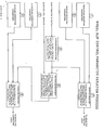
- Figure 1 is a block diagram that illustrates a method through which a wheel slip control system can use detection and correction parameters optimized for both the coupled and decoupled modes of operation according to the present invention.
- each axle will be considered to have its own AC motor through which it may be propelled and dynamically braked.
- a single propulsion brake controller will be considered to have (per truck) control over the two AC motors on the truck thereby electrically coupling the axles on the truck and enabling them to operate essentially in unison during propulsion and dynamic braking.
- the friction brakes on each axle of the truck will be considered to have friction brake control equipment in common.
- the wheel slip controller will be considered to have (per truck) control over the two axles on the truck rather than per vehicle control over all axles on the vehicle; though the present invention is also applicable to the latter arrangement.
- Figure 1 illustrates the process of the present invention through which a wheel slip control system can vary certain parameters it selects generally according to whether the axles of the truck are being decelerated using either dynamic braking or friction braking or a combination of both.
- the parameters used by the present invention may be stored, of course, in memory devices either individually or in the form of tables or both. These parameters are constants, with variable values, each of which is selected to work optimally in connection with the circumstances of its application. In other words, these parameters, whether individually or as part of a table, are generally "setup" or tuned” to the particular application for which they are intended. They are to be used within the wheel slip control system as a referent for determining other variables necessary to detect and correct wheel slip.
- each category of parameters can be further divided into two groups one of which is referred to as coupled and the other referred to as decoupled. Unlike prior art systems, the present invention will thus allow a wheel slip control system to use parameters specifically optimized for the decoupled mode of operation as well as parameters specifically optimized for the coupled mode of operation.
- the wheel slip control system shall use them in its detection logic to determine whether a wheel/axle combination exhibits slippage exceeding a critical level above which correction becomes necessary.
- the wheel slip control system will use one group of detection parameters when the axles of the truck are operating in the decoupled mode of operation. This group of parameters can be referred to as the Decoupled Detection Parameters, as represented by Block 1.
- the present invention passes to the detection logic of the wheel slip control system only those detection parameters optimized for the decoupled mode of operation.
- the wheel slip control system will use the other group of detection parameters, however, when the axles of the truck are operating in the coupled mode of operation.
- Coupled Detection Parameters This group of parameters can be referred to as the Coupled Detection Parameters, as represented by Block 2.
- the present invention passes to the detection logic of the wheel slip control system only those detection parameters optimized for the coupled mode of operation.
- the Decoupled and Coupled Detection Parameters are represented by Blocks 1 and 2, respectively, of Figure 1.
- the wheel slip control system shall use these parameters in its correction logic to eliminate slippage of the affected wheel/axle combination or at least reduce it to an acceptable level.
- the wheel slip control system will use one group of correction parameters when the axles of the truck are operating in the decoupled mode of operation. This group of parameters can be referred to as the Decoupled Correction Parameters, as represented by Block 3.
- the present invention passes to the correction logic of the wheel slip control system only those correction parameters optimized for the decoupled mode of operation.
- the wheel slip control system will use the other group of correction parameters, however, when the axles of the truck are operating in the coupled mode of operation.
- Coupled Correction Parameters This group of parameters can be referred to as the Coupled Correction Parameters, as represented by Block 4.
- the present invention passes to the correction logic of the wheel slip control system only those correction parameters optimized for the coupled mode of operation.
- the Decoupled and Coupled Correction Parameters are, again, represented by Blocks 3 and 4, respectively, of Figure 1.
- Block 5 of Figure 1 basically represents the next step in the method of the present invention.
- This block receives a signal from another known part of a passenger transit or other type of rail vehicle with which the present invention is used.
- This signal referred to as bogie tractive effort in Figure 1
- the dynamic brake feedback signal ultimately comes from the propulsion brake controller of the truck and represents the amount of dynamic (i.e., electric) braking effort applied to the axles of the truck through the AC propulsion motors.
- the dynamic brake feedback signal therefore, will be an input to Block 5 only while the axles of the truck are functioning in the coupled mode of operation.
- Block 5 basically represents a detecting device which senses the amount of dynamic braking actually applied to the axles of the truck.
- Block 5 essentially serves as a comparator which determines whether the amount of dynamic braking lies within or outside a preset zone within the range of operation for the dynamic brakes.
- the output of Block 5, hereinafter referred to as the dynamic braking detection signal will be a logical one " if for a preset time period (PTP) the amount of dynamic braking effort applied to the axles of the truck not only exceeds ten percent of the operational range but also is less than or equal to one hundred percent of the operational range.
- PTP preset time period
- the dynamic braking detection signal will be a logical zero " if for the preset time period (PTP) the amount of dynamic braking is either less than or equal to ten percent of the operational range or greater than one hundred percent of the operational range. Should the dynamic braking effort indeed lie within this preset zone of operation for the preset time period, the dynamic brake detection signal will be a logical one " thereby indicating that the axles of the truck are being dynamically braked and thus are electrically coupled.
- PTP preset time period
- Block 5 The function of Block 5 can thus be generally represented by the following relationships:
- Block 7 represents the next step in the method of the present invention.
- This block receives essentially one signal, specifically, the dynamic braking detection signal output from Block 5. It is the state of the dynamic braking detection signal that determines to which group of detection parameters the detection logic of the wheel slip control system will have access.
- the detection parameter(s) to which the detection logic will have access will change immediately from the Decoupled Detection Parameters of Block 1 to the Coupled Correction Parameters of Block 2.
- the detection parameter(s) to which the detection logic will have access will change immediately from the Coupled Detection Parameters of Block 2 to the Decoupled Correction Parameters of Block 1.
- Block 6 of Figure 1 represents the next step in the method of the present invention.
- This block receives two signals.
- the first signal that Block 6 receives is the dynamic braking detection signal output from Block 5.
- the second signal, referred to as bogie w/s control enabled in Figure 1 is the truck wheel slip control status signal. Originating in the wheel slip control system associated with the truck, this status signal indicates whether the wheel slip control on the truck is currently active. Manifested in the form of a binary signal for the logic circuitry represented by Block 6, the truck wheel slip control status signal assumes the logical one " state if the wheel slip control on the truck is active. Conversely, this status signal assumes the logical zero " state if the truck wheel slip control is inactive.
- Block 6 represents a detecting device which determines whether the wheel slip control system of the truck is active and whether the axles of the truck are electrically coupled.
- the output of Block 6, hereinafter referred to as the wheel slip state change priority signal will assume a logical one " state immediately whenever the dynamic braking detection signal received from Block 5 changes from a logical zero " to a logical one, " regardless of the state of the wheel slip control status signal. Should the dynamic braking detection signal then change to a logical zero, " the state change priority signal output from Block 6 will remain a logical one " as long as the wheel slip control status signal remains a logical one. In other words, when the dynamic braking detection signal changes to a logical zero, " the state change priority signal output from Block 6 will change to a logical zero " only when the wheel slip control status signal occupies a logical zero " state.
- Block 6 The function of Block 6 can thus be generally represented by the following relationships:
- Block 8 represents the next step in the method of the present invention.
- This block receives essentially one signal, specifically, the wheel slip state change priority signal output from Block 6. It is the state of this state change priority signal that determines to which group of correction parameters the correction logic of the wheel slip control system will have access.
- the process step of Block 6, determines the state of the state change priority signal, according to the aforementioned logic, based on the mode of operation in which the axles are operating and whether the wheel slip control is active.
- the correction parameter(s) to which the correction logic will have access will change immediately from the Decoupled Correction Parameters of Block 3 to the Coupled Correction Parameters of Block 4.
- the correction parameter(s) to which the correction logic will have access will remain the Coupled Correction Parameters of Block 4 while the wheel slip control on the truck is actively correcting a slip condition. Only after the slip has been corrected (and the wheel slip control on the truck is no longer active) will the correction parameter(s) to which the correction logic has access change to the Decoupled Correction Parameters of Block 3.
- the present method places a priority on avoiding lockup of the wheels during a change in the group of correction parameters.
- a wheel slip control system accesses the appropriate groups of detection and corrections parameters according to the present method, it can employ such parameters according to principles known in the wheel slip control art. For example, as a microprocessor executes the instructions embodied in the programming code, the wheel slip controller monitors various input signals such as rotational speeds and the rates at which the wheel/axle combinations of the truck accelerate or decelerate. From these input signals and others, it may derive signals indicative of the vehicle speed, vehicle deceleration and other required information the nature of which depends on the particular wheel slip control system at issue. Based on such signals, the wheel slip controller retrieves from the selected group of detection parameters the specific value(s) appropriate to the current operating conditions.
- various input signals such as rotational speeds and the rates at which the wheel/axle combinations of the truck accelerate or decelerate. From these input signals and others, it may derive signals indicative of the vehicle speed, vehicle deceleration and other required information the nature of which depends on the particular wheel slip control system at issue. Based on such signals, the wheel slip controller retrieve
- the wheel slip controller uses theses values in its detection logic when determining whether any of the wheel/axle combinations on the truck are actually experiencing slip. Similarly, once wheel slip is detected, the wheel slip controller retrieves from the selected group of correction parameters the specific value(s) appropriate to the degree of slip experienced by the affected wheel/axle combination. It is these values that the wheel slip controller uses in its correction logic when correcting the slip so that it ceases or reduces to an acceptable level. This overall process of detecting and correcting wheel slip, of course, occurs rapidly and continuously.
- a wheel slip control system can select the detection and correction parameters it uses according to whether the axles of the truck are being decelerated using either dynamic braking or friction braking or a combination of both.
- the present invention allows a wheel slip control system to use parameters optimized for both the coupled and decoupled modes of operation. It therefore allows a vehicle so equipped to decelerate and stop more efficiently in a shorter distance than would be possible using prior art systems.
- a wheel slip control system optimizes stop performance and wheel lock avoidance in both the coupled and decoupled modes of operation.
- each of the blocks in Figure 1 may be performed by programming code executed via a system having a microprocessor accompanied by memory storage devices.
- the information needed for each block to perform its particular function(s) may then be conveyed from one block to another by writing the necessary data to memory wherefrom it can be retrieved by any one or more other blocks requiring such data.
- the present process is preferably incorporated into the wheel slip control system, itself typically a microprocessor controlled system.
- the present invention could be implemented by a wide variety of wheel slip control systems. Though it could be carried out by a simple electronic wheel slip control system, the present invention is preferably implemented by a microprocessor based system that employs an adhesion adaptive approach to controlling wheel slip. Obvious modifications may be made, of course, depending upon the specific application in which the present invention is employed.
Landscapes
- Engineering & Computer Science (AREA)
- Transportation (AREA)
- Mechanical Engineering (AREA)
- Regulating Braking Force (AREA)
Abstract
Description
Claims (12)
- A method of varying detection and correction parameters used by a system in controlling slip of wheel/axle combinations on a truck of a rail vehicle based on whether said wheel/axle combinations are being operated in at least one of a the coupled decoupled mode of operation, said wheel slip control system for executing programming code featuring detection logic and correction logic, said method comprising the steps of:(a) deriving detection parameters optimized for both said coupled mode and said decoupled mode and correction parameters optimized for said coupled mode and said decoupled mode;(b) monitoring an amount of dynamic braking applied to said wheel/axle combinations of said truck;(c) determining whether said amount of dynamic braking lies for a preset time period within a preset zone of operation for dynamic braking of said wheel/axle combinations of said truck;(d) providing said coupled detection parameters to said detection logic of said wheel slip control system if said amount of dynamic braking lies within said preset zone for said preset time period;(e) providing said decoupled detection parameters to said detection logic of said wheel slip control system if said amount of dynamic braking fails to lie within said preset zone for said preset time period;(f) providing said coupled correction parameters to said correction logic of said wheel slip control system if said amount of dynamic braking lies within said preset zone for said preset time period; and(g) providing said decoupled correction parameters to said correction logic of said wheel slip control system only if said amount of dynamic braking fails to lie within said preset zone for said preset time period when said wheel slip control system is inactive.
- The method of varying detection and correction parameters as recited in claim 1 wherein said preset zone lies approximately between ten percent and one hundred percent of operational range of operation for said dynamic braking.
- The method of varying detection and correction parameters as recited in claim 1 wherein said preset time period is approximately one hundred milliseconds.
- A method of selecting detection and correction parameters for use by a wheel slip control system according to whether wheel/axle combinations on a truck of a rail vehicle are operating in a coupled or a decoupled mode of operation, said wheel slip control system for executing programming code featuring detection logic and correction logic, said method comprising the steps of:(a) monitoring an amount of dynamic braking applied to said wheel/axle combinations of said truck;(b) generating a dynamic braking detection signal having a logical one state when said amount of dynamic braking lies for a preset time period within a preset zone of operation for dynamic braking of said wheel/axle combinations of said truck and a logical zero state when said amount of dynamic braking fails to lie within said preset zone for said preset time period;(c) providing said detection parameters optimized for said coupled mode to said detection logic of said wheel slip control system when said dynamic braking detection signal bears a logical one state;(d) providing said detection parameters optimized for said decoupled mode to said detection logic of said wheel slip control system when said dynamic braking detection signal bears a logical zero state;(e) receiving a wheel slip control status signal from said wheel slip control system which determine whether said wheel slip control system of said truck is active;(f) generating a wheel slip state change priority signal having a logical one state when said dynamic braking detection signal changes to a logical one state and a logical zero state only if said dynamic braking detection signal changes to a logical zero state when said wheel slip control status signal indicates that said wheel slip control system is inactive;(g) providing said correction parameters optimized for said coupled mode to said correction logic of said wheel slip control system when said wheel slip state change priority signal bears a logical one state; and(h) providing said correction parameters optimized for said decoupled mode to said correction logic of said wheel slip control system when said wheel slip state change priority signal bears a logical zero state.
- The method of varying detection and correction parameters as recited in claim 4 wherein said preset zone lies approximately between ten percent and one hundred percent of an operational range of operation for said dynamic braking.
- The method of varying detection and correction parameters as recited in claim 4 wherein said preset time period is approximately one hundred milliseconds.
- A method of selecting detection and correction parameters for use by a wheel slip control system according to whether wheel/axle combinations on a truck of a rail vehicle are operating in a coupled or a decoupled mode of operation, said wheel slip control system for executing programming code featuring detection logic and correction logic, said method comprising the steps of:(a) monitoring an amount of dynamic braking applied to said wheel/axle combinations of said truck;(b) determining whether said amount of dynamic braking lies for a preset time period within a preset zone of operation for dynamic braking of said wheel/axle combinations of said truck;(c) providing said detection parameters optimized for said coupled mode to said detection logic of said wheel slip control system if said amount of dynamic braking lies within said preset zone for said preset time period;(d) providing said detection parameters optimized for said decoupled mode to said detection logic of said wheel slip control system if said amount of dynamic braking fails to lie within said preset zone for said preset time period;(e) providing said correction parameters optimized for said coupled mode to said correction logic of said wheel slip control system if said amount of dynamic braking lies within said preset zone for said preset time period; and(f) providing said correction parameters optimized for said decoupled mode to said correction logic of said wheel slip control system only if said amount of dynamic braking fails to lie within said preset zone for said preset time period when said wheel slip control system is inactive.
- The method of varying detection and correction parameters as recited in claim 7 wherein said preset zone lies approximately between ten percent and one hundred percent of operational range of operation for said dynamic braking.
- The method of varying detection and correction parameters as recited in claim 7 wherein said preset time period is approximately one hundred milliseconds.
- A method of varying detection and correction parameters used by a system in controlling slip of wheel/axle combinations on a truck of a rail vehicle based on whether said wheel/axle combinations are being operated in a coupled or decoupled mode of operation, said wheel slip control system for executing programming code featuring detection logic and correction logic, said method comprising the steps of:(a) deriving detection parameters optimized for both said coupled mode and said decoupled mode and correction parameters optimized for both said coupled mode and(b) monitoring an amount of dynamic braking applied to said wheel/axle combinations of said truck;(c) generating a dynamic braking detection signal having a logical one state when said amount of dynamic braking lies for a preset time period within a preset zone of operation for dynamic braking of said wheel/axle combinations of said truck and a logical zero state when said amount of dynamic braking fails to lie within said preset zone for said preset time period;(d) providing said coupled detection parameters to said detection logic of said wheel slip control system when said dynamic braking detection signal bears a logical one state;(e) providing said decoupled detection parameters to said detection logic of said wheel slip control system when said dynamic braking detection signal bears a logical zero state;(f) receiving a wheel slip control status signal from said wheel slip control system to determine whether said wheel slip control system of said truck is active;(g) generating a wheel slip state change priority signal having a logical one state when said dynamic braking detection signal changes to a logical one state and a logical zero state only if said dynamic braking detection signal changes to a logical zero state when said wheel slip control status signal indicates that said wheel slip control system is inactive;(h) providing said coupled correction parameters to said correction logic of said wheel slip control system when said wheel slip state change priority signal bears a logical one state; and(i) providing said decoupled correction parameters to said correction logic of said wheel slip control system when said wheel slip state change priority signal bears a logical zero state.
- The method of varying detection and correction parameters as recited in claim 10 wherein said preset zone lies approximately between ten percent and one hundred percent of an operational range of operation for said dynamic braking.
- The method of varying detection and correction parameters as recited in claim 10 wherein said preset time period is approximately one hundred milliseconds.
Applications Claiming Priority (2)
| Application Number | Priority Date | Filing Date | Title |
|---|---|---|---|
| US08/852,799 US5961564A (en) | 1997-05-07 | 1997-05-07 | Wheel slip control parameter variation process |
| US852799 | 1997-05-07 |
Publications (2)
| Publication Number | Publication Date |
|---|---|
| EP0876944A2 true EP0876944A2 (en) | 1998-11-11 |
| EP0876944A3 EP0876944A3 (en) | 2000-07-05 |
Family
ID=25314252
Family Applications (1)
| Application Number | Title | Priority Date | Filing Date |
|---|---|---|---|
| EP98101935A Withdrawn EP0876944A3 (en) | 1997-05-07 | 1998-02-05 | Wheel slip control parameter variation process |
Country Status (6)
| Country | Link |
|---|---|
| US (1) | US5961564A (en) |
| EP (1) | EP0876944A3 (en) |
| JP (1) | JP3340673B2 (en) |
| AU (1) | AU720708B2 (en) |
| BR (1) | BR9801089A (en) |
| CA (1) | CA2218574C (en) |
Cited By (2)
| Publication number | Priority date | Publication date | Assignee | Title |
|---|---|---|---|---|
| WO2016207419A1 (en) * | 2015-06-25 | 2016-12-29 | Knorr-Bremse Systeme für Schienenfahrzeuge GmbH | Rail vehicle braking system and method for operating a rail vehicle braking system |
| WO2022012966A1 (en) * | 2020-07-13 | 2022-01-20 | Knorr-Bremse Systeme für Schienenfahrzeuge GmbH | Control apparatus and control method for an anti-slide system |
Families Citing this family (8)
| Publication number | Priority date | Publication date | Assignee | Title |
|---|---|---|---|---|
| WO2001028469A2 (en) * | 1999-10-21 | 2001-04-26 | Sdgi Holdings, Inc. | Devices and techniques for a posterior lateral disc space approach |
| KR100583269B1 (en) * | 2003-12-19 | 2006-05-24 | 한국철도기술연구원 | Wheel slide detection system of rolling stock |
| EP1931545B1 (en) * | 2005-09-16 | 2010-06-16 | Wabtec Holding Corporation | Pneumatic emergency brake assurance module |
| CN103213600B (en) * | 2013-03-27 | 2015-09-09 | 株洲南车时代电气股份有限公司 | A kind of anti-slip back control system of guideway vehicle and method thereof |
| EP2949523B2 (en) * | 2014-05-27 | 2024-12-18 | Jörg Beutler | Weight-independent safety brake |
| CN110929541B (en) * | 2019-11-18 | 2021-01-01 | 南京大树智能科技股份有限公司 | Panoramic cigarette two-dimensional code scanning system |
| CN111231913A (en) * | 2020-02-17 | 2020-06-05 | 中南大学 | Active anti-skid control method, controller and control device for subway |
| CN112487705B (en) * | 2020-11-12 | 2024-07-19 | 中科慧拓(北京)科技有限公司 | Mine car parameter optimization method and system based on real-time data |
Citations (6)
| Publication number | Priority date | Publication date | Assignee | Title |
|---|---|---|---|---|
| US4071282A (en) | 1976-02-04 | 1978-01-31 | Vapor Corporation | Slip-slide detector system for railway car wheels |
| US4491920A (en) | 1981-04-24 | 1985-01-01 | American Standard Inc. | Rate polarity shift wheel-slip control system |
| US4941099A (en) | 1988-05-16 | 1990-07-10 | American Standard Inc. | Electronic adhesion adaptive wheel slide protection arrangement function |
| US5471387A (en) | 1994-04-18 | 1995-11-28 | Westinghouse Air Brake Company | Method of and apparatus for the combined detection of speed varying energy level wheel slip detection and determination of wheel slip intensity of a railway vehicle brake system |
| CA2152739A1 (en) | 1995-05-08 | 1996-11-09 | James A. Wood | Proportional Polarity Shift Wheel Slide Protection |
| US5654889A (en) | 1995-06-02 | 1997-08-05 | Westinghouse Air Brake Company | Simplified pattern recognition wheel slide protection |
Family Cites Families (2)
| Publication number | Priority date | Publication date | Assignee | Title |
|---|---|---|---|---|
| DE2444738A1 (en) * | 1974-09-19 | 1976-04-08 | Knorr Bremse Gmbh | Anti skid braking system for tracked vehicles - switches from electro dynamic to friction braking on appearance of axle wheel locking |
| US4819168A (en) * | 1988-01-19 | 1989-04-04 | Aeg Westinghouse Transportation Systems, Inc. | Train control having improved wheel wear adjustment for more accurate train operation |
-
1997
- 1997-05-07 US US08/852,799 patent/US5961564A/en not_active Expired - Lifetime
- 1997-10-16 CA CA002218574A patent/CA2218574C/en not_active Expired - Lifetime
-
1998
- 1998-01-23 AU AU52727/98A patent/AU720708B2/en not_active Ceased
- 1998-02-05 EP EP98101935A patent/EP0876944A3/en not_active Withdrawn
- 1998-04-17 BR BR9801089-1A patent/BR9801089A/en not_active IP Right Cessation
- 1998-05-07 JP JP12465298A patent/JP3340673B2/en not_active Expired - Fee Related
Patent Citations (6)
| Publication number | Priority date | Publication date | Assignee | Title |
|---|---|---|---|---|
| US4071282A (en) | 1976-02-04 | 1978-01-31 | Vapor Corporation | Slip-slide detector system for railway car wheels |
| US4491920A (en) | 1981-04-24 | 1985-01-01 | American Standard Inc. | Rate polarity shift wheel-slip control system |
| US4941099A (en) | 1988-05-16 | 1990-07-10 | American Standard Inc. | Electronic adhesion adaptive wheel slide protection arrangement function |
| US5471387A (en) | 1994-04-18 | 1995-11-28 | Westinghouse Air Brake Company | Method of and apparatus for the combined detection of speed varying energy level wheel slip detection and determination of wheel slip intensity of a railway vehicle brake system |
| CA2152739A1 (en) | 1995-05-08 | 1996-11-09 | James A. Wood | Proportional Polarity Shift Wheel Slide Protection |
| US5654889A (en) | 1995-06-02 | 1997-08-05 | Westinghouse Air Brake Company | Simplified pattern recognition wheel slide protection |
Cited By (3)
| Publication number | Priority date | Publication date | Assignee | Title |
|---|---|---|---|---|
| WO2016207419A1 (en) * | 2015-06-25 | 2016-12-29 | Knorr-Bremse Systeme für Schienenfahrzeuge GmbH | Rail vehicle braking system and method for operating a rail vehicle braking system |
| US10899326B2 (en) | 2015-06-25 | 2021-01-26 | Knorr-Bremse Systeme für Schienenfahrzeuge GmbH | Rail vehicle braking system and method for operating a rail vehicle braking system |
| WO2022012966A1 (en) * | 2020-07-13 | 2022-01-20 | Knorr-Bremse Systeme für Schienenfahrzeuge GmbH | Control apparatus and control method for an anti-slide system |
Also Published As
| Publication number | Publication date |
|---|---|
| EP0876944A3 (en) | 2000-07-05 |
| US5961564A (en) | 1999-10-05 |
| BR9801089A (en) | 1999-09-21 |
| AU5272798A (en) | 1998-08-13 |
| JPH10315951A (en) | 1998-12-02 |
| CA2218574C (en) | 2002-01-01 |
| AU720708B2 (en) | 2000-06-08 |
| JP3340673B2 (en) | 2002-11-05 |
| CA2218574A1 (en) | 1998-11-07 |
Similar Documents
| Publication | Publication Date | Title |
|---|---|---|
| US5961564A (en) | Wheel slip control parameter variation process | |
| US4932726A (en) | Anti-skid brake control system with vehicle speed dependent variable slippage threshold feature | |
| US8924048B2 (en) | Graduated vehicle braking | |
| US5428538A (en) | Sanding control system for railway vehicles | |
| CN113696915B (en) | High-speed braking large-creep adhesion control method and device | |
| CN105216790A (en) | For driving the method for hybrid vehicle | |
| JPH10509111A (en) | Circuit device for anti-lock control type brake device | |
| US5544057A (en) | Load setting device for railway cars | |
| CN109153380B (en) | Method and device for controlling or regulating a brake system | |
| CA2123754C (en) | Method of and apparatus for the combined detection of speed varying energy level wheel slip detection and determination of wheel slip intensity of a railway vehicle brake system | |
| US5975656A (en) | Universal wheel slip force control logic | |
| EP1291228B1 (en) | Method for controlling brake systems | |
| US5740043A (en) | Relative spin speed traction control | |
| JP2001128302A (en) | Safety method of train operation | |
| JPH11103508A (en) | Variable type acceleration/deceleration pattern generation method | |
| JPH02254052A (en) | Spin propulsive regulator of energy accumulative wheel | |
| JP2001204102A (en) | Device for controlling power regenerative brake | |
| JPH07245804A (en) | Skid detecting apparatus for railway rolling stocks | |
| JP2000108864A (en) | Brake controller | |
| CN116080701A (en) | Braking method, braking system, braking device, braking medium and train | |
| SK285922B6 (en) | Device for controlling the adherence of an electrically driven railway train | |
| JPH0539019A (en) | Brake controller for rolling stock | |
| JP2814733B2 (en) | Operation control equipment for self-propelled trolley | |
| CN116424394A (en) | Train overturn prevention method, system, device and storage medium | |
| JPH10117408A (en) | Drive and braking controller for train and the like by acceleration and deceleration control method |
Legal Events
| Date | Code | Title | Description |
|---|---|---|---|
| PUAI | Public reference made under article 153(3) epc to a published international application that has entered the european phase |
Free format text: ORIGINAL CODE: 0009012 |
|
| AK | Designated contracting states |
Kind code of ref document: A2 Designated state(s): DE FR GB SE |
|
| AX | Request for extension of the european patent |
Free format text: AL;LT;LV;MK;RO;SI |
|
| PUAL | Search report despatched |
Free format text: ORIGINAL CODE: 0009013 |
|
| AK | Designated contracting states |
Kind code of ref document: A3 Designated state(s): AT BE CH DE DK ES FI FR GB GR IE IT LI LU MC NL PT SE |
|
| AX | Request for extension of the european patent |
Free format text: AL;LT;LV;MK;RO;SI |
|
| 17P | Request for examination filed |
Effective date: 20000909 |
|
| AKX | Designation fees paid |
Free format text: DE FR GB SE |
|
| 17Q | First examination report despatched |
Effective date: 20060816 |
|
| GRAP | Despatch of communication of intention to grant a patent |
Free format text: ORIGINAL CODE: EPIDOSNIGR1 |
|
| GRAS | Grant fee paid |
Free format text: ORIGINAL CODE: EPIDOSNIGR3 |
|
| STAA | Information on the status of an ep patent application or granted ep patent |
Free format text: STATUS: THE APPLICATION IS DEEMED TO BE WITHDRAWN |
|
| 18D | Application deemed to be withdrawn |
Effective date: 20070901 |