EP0876580B1 - A method and a device for inductive measurement of measures and positions of objects of electrically conductive material - Google Patents
A method and a device for inductive measurement of measures and positions of objects of electrically conductive material Download PDFInfo
- Publication number
- EP0876580B1 EP0876580B1 EP96935660A EP96935660A EP0876580B1 EP 0876580 B1 EP0876580 B1 EP 0876580B1 EP 96935660 A EP96935660 A EP 96935660A EP 96935660 A EP96935660 A EP 96935660A EP 0876580 B1 EP0876580 B1 EP 0876580B1
- Authority
- EP
- European Patent Office
- Prior art keywords
- time
- coil
- region
- measured
- transmitter coil
- Prior art date
- Legal status (The legal status is an assumption and is not a legal conclusion. Google has not performed a legal analysis and makes no representation as to the accuracy of the status listed.)
- Expired - Lifetime
Links
Images


Classifications
-
- G—PHYSICS
- G01—MEASURING; TESTING
- G01V—GEOPHYSICS; GRAVITATIONAL MEASUREMENTS; DETECTING MASSES OR OBJECTS; TAGS
- G01V3/00—Electric or magnetic prospecting or detecting; Measuring magnetic field characteristics of the earth, e.g. declination, deviation
- G01V3/08—Electric or magnetic prospecting or detecting; Measuring magnetic field characteristics of the earth, e.g. declination, deviation operating with magnetic or electric fields produced or modified by objects or geological structures or by detecting devices
- G01V3/10—Electric or magnetic prospecting or detecting; Measuring magnetic field characteristics of the earth, e.g. declination, deviation operating with magnetic or electric fields produced or modified by objects or geological structures or by detecting devices using induction coils
- G01V3/104—Electric or magnetic prospecting or detecting; Measuring magnetic field characteristics of the earth, e.g. declination, deviation operating with magnetic or electric fields produced or modified by objects or geological structures or by detecting devices using induction coils using several coupled or uncoupled coils
-
- G—PHYSICS
- G01—MEASURING; TESTING
- G01B—MEASURING LENGTH, THICKNESS OR SIMILAR LINEAR DIMENSIONS; MEASURING ANGLES; MEASURING AREAS; MEASURING IRREGULARITIES OF SURFACES OR CONTOURS
- G01B7/00—Measuring arrangements characterised by the use of electric or magnetic techniques
- G01B7/003—Measuring arrangements characterised by the use of electric or magnetic techniques for measuring position, not involving coordinate determination
Definitions
- the present invention relates to a method and a device for non-contacting measurement of measures and positions of objects of electrically conductive material based on electromagnetic induction.
- the invention may be used when manufacturing metal products as tube, rod or beam, in which it is desired to measure the measures and positions of these products.
- the invention may also be used for measurement on products made of graphite, electrically conductive ceramic, or the like.
- One known method for non-contacting measurement of positions and various measures, such as height and width, of tube, rod, beam or the like products is to use optical methods based on shading or reflection of beams, or by processing of images taken by a video camera.
- sinusoidal currents in the transmitter coil may be used, as described in US 4475083, or a constant current which is suddenly broken, such as described in US 5059902, may be used.
- the latter method is more robust from the point of view of measurement technique and facilitates the separation of different properties of the measuring object.
- One problem with these measurement devices, however, is to determine the measures of the object when its position is changed.
- US 5270646 discloses a method of arranging coils so as to achieve measurement of the width of a strip.
- the technique can only be used for strip of relatively limited width.
- the accuracy is not sufficient, primarily when there are large distances between the strip and the measuring coils, which is due to difficulties in correctly compensating for variations in the distance.
- the transmitter and receiver coils are arranged with the same symmetry axis or are located on different sides of the object. It also occurs that the same coil is used as transmitter and receiver coil.
- the magnetic field generated by the transmitter coil then becomes substantially perpendicular to the surface of the object at the measuring point, or at least has a large component towards the surface of the object. This results in currents and magnetic fields from different depths into the object contributing to the measurement signal which thus becomes both material-dependent and dependent on the thickness and shape of the measuring object in a relatively large region around the location where measurement is to take place.
- the invention is based, as shown in Figure 1, on placing an object 1 to be measured, a transmitter coil 2, and a receiver coil 3 in relation to each other in such a way that magnetic field 4 generated by the transmitter coil at a measuring region 5, defined as the region around a conceived measuring point 6, is substantially parallel to the surface of the measuring object at the region to be measured, or, for an object with a curved surface, parallel to a tangential plane 7 at the measuring point 6.
- the measurement device then becomes most sensitive to movements in the direction of a line 8, indicated below as the x direction or the x line, perpendicular to the tangential plane at the measuring point.
- the receiver coil is to be located such that a conceived field line 4, which symbolizes the magnetic field, touches the measuring region and in its extension reaches the receiver coil.
- a substantially symmetrical location of the coils in relation to the region to be measured in question and where the transmitter coil, the region to be measured, and the receiver coil lie on one and the same circular arc and where the circular arc at the region to be measured is curved outwardly.
- the invention also functions in the case of a minor deviation from a location according to the above.
- Measurements with an arrangement of the coils according to the invention are sensitive to movement of the object to be measured perpendicular to the magnetic field at the region to be measured, that is, in the x direction, whereas the measurements are only influenced to a marginal extent by the movements of the object to be measured in parallel with the magnetic field, indicated below as the y direction or the y line.
- the currents which are induced in the object to be measured because of the magnetic field which is parallel to the region to be measured are concentrated at the region to be measured This means that the voltage which is induced in the receiver coil is substantially dependent on the magnetic field in the measuring region and the position of the receiver coil.
- the shape of the object to be measured and its position outside the region to be measured will have a negligible influence on the result of the measurement.
- a small change of the position of the region to be measured in the x direction results in a linear change of the voltage induced in the receiver coil.
- the voltage induced in the receiver coil is stationary with respect to small changes of the position of the region to be measured in the y direction. This means that the measurement signal is sensitive to small changes in position perpendicular to the surface of the region to be measured but is influenced only to a marginal extent by small changes in position parallel to the region to be measured. Changes in position perpendicular to the surface of the object to be measured can thus be measured selectively.
- US 5059902 describes an advantageous method of supplying a transmitter coil. It describes supply with a constant current which has a sufficient duration for the magnetic field to be considered quasi-static. The magnetic field which is generated when this current is interrupted has the same shape as the quasi-stationary field, but the opposite direction. In this way, after interruption of the current, the field continues to be parallel to the region to be measured.
- the direction of the field at the region to be measured varies during one period of the alternating voltage. For a correct measurement, the direction of the field at the region to be measured must, on average, be parallel for one period, which is difficult to obtain.
- the voltage induced in the receiver coil as a function of the time, after the constant current in the transmitter coil has been interrupted, comprises a short and a rapidly diminishing voltage pulse which is induced by the rapidly decreasing magnetic field in the air between the coils and the object to be measured, and a considerably more slowly diminishing voltage pulse which relates to the magnetic field within the object to be measured which decreases slowly because of the skin effect (current diffusion).
- the fast voltage pulse immediately after closing of the supply voltage of the transmitter coil is essentially independent of the electrical conductivity and the magnetic permeability of the object to be measured and is substantially a function of the geometry of the magnetic field outside the object to be measured and the resistance in the measuring circuit.
- the fast voltage signal is in practice independent of the material as long as its duration is short compared with the time for current diffusion in the region to be measured.
- the induced voltage can be evaluated as a measure of the position of the object to be measured relative to the coils.
- the position of the region to be measured of the object to be measured on a line perpendicular to its surface can then be calculated.
- a measurement is carried out with a corresponding set of a transmitter coil and a receiver coil for measuring the position of a region to be measured of the object to be measured with a measuring point on the extension of the x line through the object to be measured and with a tangential plane parallel to the tangential plane 7, it is possible, by a combination of the results from the two measurements, to determine the length in the x direction between the two tangential planes. Both measurements can be made simultaneously or in rapid succession after each other.
- a plurality of associated transmitter and receiver coils according to the invention are placed around the object to be measured.
- the supply current of the transmitter coils is then normally interrupted at different times in order for measurements not to influence each other.
- a measurement device when using a constant supply current through the transmitter coil which is interrupted after a time which is sufficient for creating a quasi-static magnetic field in the air, is within wide limits independent of the material properties of the object to be measured, such as conductivity and permeability.
- the material properties would influence a similar inductive measurement with a sinusoidal alternating current. Since each coil system is only influenced by the surface of the object to be measured within a small measuring range, independent of the shape of the whole object to be measured, the invention can be easily adapted to a wide variety of objects to be measured.
- the requirement for a magnetic field substantially parallel to the surface of the object to be measured in the measuring to be measured can be fulfilled in a plurality of different ways and thus allows great flexibility in the location of the coils.
- Figure 2 is a sketch showing the principle of a measurement device for measuring the position of the region according to the invention. It comprises an object to be measured 1, a transmitter coil 2 and a receiver coil 3 which are arranged such that a conceived magnetic field line 4 which extends from the transmitter coil 2 touches the region 5 to be measured and reaches the receiver coil 3.
- the field line represents the quasi-static magnetic field which is achieved after connection of supply to the transmitter coil with a constant current for a time which is long compared to the time for the diffusion of current and magnetic field in the region to be measured.
- a measuring point 7 within the region to be measured is touched by a tangential plane 7 in the y direction.
- the x line mentioned under the summary of the invention, will be referred to below, for the reasons stated, as a symmetry line 8 perpendicular to the tangential plane at the measuring point.
- the transmitter coil and the receiver coil are placed substantially symmetrically on different sides of the measuring point in such a way that the coils and the measuring point substantially lie on one and the same circular arc 9 with a centre 10 outside the object to be measured on the symmetry line 8.
- the centre of the circular arc is suitably selected as the origin of coordinates for distance measurements in the x direction, that is, along the symmetry line.
- the axial lines 11a and 11b of the coils through the coils are adjusted for an optimum measurement result.
- the axial line 11a of the coil touches the arc 9.
- the angle 12a between the symmetry line 8 and a line from the centre 10 to the transmitter coil is equal to the angle 12b between the symmetry line 8 and a line from the centre to the receiver coil.
- a measurement device is not particularly sensitive to deviations from the preferred location according to the above means that the device provides relevant measures of a change of the position of the region to be measured if the change is smaller than 10-30 % of the distance between the region to be measured and any of the coils.
- Figure 3 schematically shows the current I in the transmitter coil and the voltage U, induced in the receiver coil, as a function of the time t.
- the current through the transmitter coil is constant till the time t1, where it is interrupted.
- the duration of the current has then been longer than the time of the penetration of the magnetic field into the material of the object to be measured within the region to be measured such that the magnetic field is quasi-static.
- the decreasing magnetic field in the air around the object to be measured induces a voltage pulse S1 in the receiver coil of a short duration between the times t1 and t2.
- the magnetic field which diffuses out of the object to be measured, induces a much smaller and more slowly decreasing voltage pulse S2.
- a measure of the x position of the region to be measured on the symmetry line 8 according to Figure 2, or the distance of the region to be measured from a given reference point, for example the centre 10 of the above-mentioned arc, can then be derived from a linear combination of the integral of the voltage pulse S1 between t1 and t2 and the integral of that part of the voltage pulse S2 which lies between t2 and t3 according to Figure 2.
- the time t3 is preferably chosen such that t3-t2 is of the same order of magnitude as the time difference t2-t1.
- the linear combination M which can thus provide a measure of the x position of the object to be measured can be expressed as where the coefficients a and b are chosen after calibration with measured objects made of materials with different electrical conductivity such that the difference in M between the materials is as small as possible. If the time difference t3-t2 is chosen equal to 2(t2-t1), a and b will be substantially equal and no calibration according to the above need be made.
- FIG. 4 shows two receiver coils 3a and 3b with a common centre point 13 on the circular arc 9 and centre lines 11b and 11c perpendicular to each other.
- the centre line of one coil shall be directed towards the measuring region.
- this is coil 3a with the centre line 11b directed towards the measuring point.
- the relationship between the measurement signals from these two coils is, within wide limits, substantially only dependent on the position of the region to be measured in the x direction.
- FIG. 5 An additional embodiment with two receiver coils 3 and 4 is shown in Figure 5.
- the coils are here placed on different sides of the circular arc 9 and with substantially parallel centre lines 11b and 11c parallel to the symmetry line 8.
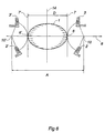
- Figure 6 shows an example of how, by combination of two measurement devices with two pairs of associated transmitter and receiver coils according to the invention, it is possible to determine two measures of the object to be measured, the position of the object to be measured, and the length D of the symmetry line 8 of the object to be measured in the direction of the x axis.
- Figure 6 is obtained by a reflection of Figure 2 on a line 14 parallel to the tangential plane 7. All the reflected features of Figure 2 are provided with '; for example, 3' is the reflected receiver coil.
- the distances M1 and M2 from two reference points, for example the centres 10 and 10' of the arc, to the measuring points 6 and 6' of the region to be measured are obtained.
- the difference M1 - M2 provides information about the placement of the object to be measured on the line between the centres of the arcs.
- a measurement operation by means of a device according to the invention which comprises generation of the supply current to the transmitter coils, measurement and evaluation of the voltage induced across the receiver coils, is carried out with conventional methods which may be analog, digital, or a combination of digital and analog technique.
- the generation of the supply current and the integration of the induced voltages are carried out by means of analog electronics whereas the evaluation of the integrated signals with respect to the measures and position of the object to be measured is performed with the aid of digital technique in a microprocessor.
- a magnetization unit 15 for magnetization of the transmitter coil and a calculating unit 16.
Landscapes
- Physics & Mathematics (AREA)
- General Physics & Mathematics (AREA)
- Engineering & Computer Science (AREA)
- Remote Sensing (AREA)
- Life Sciences & Earth Sciences (AREA)
- Electromagnetism (AREA)
- Environmental & Geological Engineering (AREA)
- Geology (AREA)
- General Life Sciences & Earth Sciences (AREA)
- Geophysics (AREA)
- Measurement Of Length, Angles, Or The Like Using Electric Or Magnetic Means (AREA)
Applications Claiming Priority (3)
| Application Number | Priority Date | Filing Date | Title |
|---|---|---|---|
| SE9503583 | 1995-10-13 | ||
| SE9503583A SE506154C2 (sv) | 1995-10-13 | 1995-10-13 | Förfarande och anordning för induktiv mätning av mått och läge hos objekt av elektriskt ledande material |
| PCT/SE1996/001207 WO1997014013A1 (en) | 1995-10-13 | 1996-09-27 | A method and a device for inductive measurement of measures and positions of objects of electrically conductive material |
Publications (2)
| Publication Number | Publication Date |
|---|---|
| EP0876580A1 EP0876580A1 (en) | 1998-11-11 |
| EP0876580B1 true EP0876580B1 (en) | 2001-12-05 |
Family
ID=20399816
Family Applications (1)
| Application Number | Title | Priority Date | Filing Date |
|---|---|---|---|
| EP96935660A Expired - Lifetime EP0876580B1 (en) | 1995-10-13 | 1996-09-27 | A method and a device for inductive measurement of measures and positions of objects of electrically conductive material |
Country Status (7)
| Country | Link |
|---|---|
| US (1) | US6236198B1 (sv) |
| EP (1) | EP0876580B1 (sv) |
| JP (1) | JPH11513496A (sv) |
| AT (1) | ATE210272T1 (sv) |
| DE (1) | DE69617741T2 (sv) |
| SE (1) | SE506154C2 (sv) |
| WO (1) | WO1997014013A1 (sv) |
Families Citing this family (9)
| Publication number | Priority date | Publication date | Assignee | Title |
|---|---|---|---|---|
| US6577118B2 (en) * | 2001-02-02 | 2003-06-10 | B.D.H. Industries Inc. | System and method for measuring liquid metal levels or the like |
| SE525078C2 (sv) * | 2001-06-29 | 2004-11-23 | Abb Ab | Metod samt induktiv mätanordning för detektering av mittpunkten hos ett elektriskt ledande material |
| US20040008022A1 (en) * | 2002-07-11 | 2004-01-15 | Viola Jeffrey L. | Current sensor |
| SE527091C2 (sv) * | 2003-12-31 | 2005-12-20 | Abb Ab | Metod och anordning för beröringsfri mätning av tjocklek och elektriska ledningsförmåga hos ett mätobjekt |
| CN1834690B (zh) * | 2006-04-12 | 2010-08-18 | 郭有军 | 通过式金属探测系统 |
| DE102010031147A1 (de) * | 2010-05-07 | 2011-11-10 | Robert Bosch Gmbh | Erfassung eines metallischen oder magnetischen Objekts |
| WO2013036983A1 (en) | 2011-09-15 | 2013-03-21 | Orocobre Limited | Process for producing lithium carbonate from concentrated lithium brine |
| GB2507269A (en) * | 2012-10-23 | 2014-04-30 | Wfs Technologies Ltd | Determining the spatial relationship between two surfaces |
| DE102013209805A1 (de) * | 2013-05-27 | 2014-11-27 | iCONTROLS k.s. | Induktiver Sensor |
Family Cites Families (11)
| Publication number | Priority date | Publication date | Assignee | Title |
|---|---|---|---|---|
| US3539911A (en) * | 1968-06-21 | 1970-11-10 | Dresser Ind | Induction well logging apparatus having investigative field of asymmetric sensitivity |
| US3693075A (en) * | 1969-11-15 | 1972-09-19 | Forster F M O | Eddy current system for testing tubes for defects,eccentricity,and wall thickness |
| SE418996B (sv) | 1977-09-19 | 1981-07-06 | Atomenergi Ab | Forfarande och anordning for elektromagnetisk storhetsmetning i samband med ett elektriskt ledande material med hog temperatur |
| US4591785A (en) * | 1983-10-25 | 1986-05-27 | Mobil Oil Corporation | Method for detecting soft spots in the hardness of steel casing |
| GB2158240B (en) * | 1984-04-26 | 1988-01-27 | Standard Telephones Cables Ltd | A null-balanced proximity sensor |
| US4686471A (en) * | 1984-10-09 | 1987-08-11 | Kawasaki Steel Corporation | System for online-detection of the transformation value and/or flatness of steel or a magnetic material by detecting changes in induced voltages due to interlinked magnetic fluxes in detecting coils |
| SE451886B (sv) | 1986-10-10 | 1987-11-02 | Sten Linder | Sett och anordning for beroringsfri metning av storheter hos eller i anslutning till elektriskt ledande material |
| US4950986A (en) * | 1988-06-27 | 1990-08-21 | Combustion Engineering, Inc. | Magnetic proximity sensor for measuring gap between opposed refiner plates |
| SE468405B (sv) | 1991-05-02 | 1993-01-11 | Asea Brown Boveri | Foerfarande vid kantlaegesbestaemning av metalliska material samt kantlaegesmaetare foer genomfoerande av foerfarandet |
| DE4126921C2 (de) | 1991-08-14 | 1996-01-18 | Elmeg | Vorrichtung zur induktiven Messung der Lage eines Metallbandes |
| EP0529181A3 (en) * | 1991-08-28 | 1993-05-26 | Nishimatsu Construction Co., Ltd. | Method and system for searching reinforcing steel in concrete |
-
1995
- 1995-10-13 SE SE9503583A patent/SE506154C2/sv not_active IP Right Cessation
-
1996
- 1996-09-27 EP EP96935660A patent/EP0876580B1/en not_active Expired - Lifetime
- 1996-09-27 DE DE69617741T patent/DE69617741T2/de not_active Expired - Fee Related
- 1996-09-27 WO PCT/SE1996/001207 patent/WO1997014013A1/en active IP Right Grant
- 1996-09-27 AT AT96935660T patent/ATE210272T1/de not_active IP Right Cessation
- 1996-09-27 JP JP9514964A patent/JPH11513496A/ja active Pending
- 1996-09-27 US US09/051,333 patent/US6236198B1/en not_active Expired - Fee Related
Also Published As
| Publication number | Publication date |
|---|---|
| SE9503583L (sv) | 1997-04-14 |
| EP0876580A1 (en) | 1998-11-11 |
| ATE210272T1 (de) | 2001-12-15 |
| SE506154C2 (sv) | 1997-11-17 |
| SE9503583D0 (sv) | 1995-10-13 |
| WO1997014013A1 (en) | 1997-04-17 |
| DE69617741D1 (de) | 2002-01-17 |
| JPH11513496A (ja) | 1999-11-16 |
| DE69617741T2 (de) | 2002-08-08 |
| US6236198B1 (en) | 2001-05-22 |
Similar Documents
| Publication | Publication Date | Title |
|---|---|---|
| JP4585637B2 (ja) | 金属妨害の検知 | |
| EP3702738B1 (en) | Method for increasing the position measurement accuracy using inductive position sensor | |
| EP0129282B1 (en) | Measuring device for the "contactless" measurement of large thicknesses, for metal materials above the curie temperature | |
| JP4814092B2 (ja) | ターゲット物体の経路を記録する装置及び方法 | |
| EP0876580B1 (en) | A method and a device for inductive measurement of measures and positions of objects of electrically conductive material | |
| KR20130038796A (ko) | 비접촉 자기 선형 위치 센서 | |
| US9335151B2 (en) | Film measurement | |
| EP0514698B1 (en) | Method and device for edge position determination of metallic materials | |
| JPS5856912B2 (ja) | 2次元磁気スケ−ル装置 | |
| CN113710997B (zh) | 磁感测系统、检测装置以及磁干扰的偏置方法 | |
| JP2017150904A (ja) | 探傷装置および探傷方法 | |
| EP0876581B1 (en) | Inductive device for determining measures and positions of measuring objects of electrically conductive material | |
| US20180217099A1 (en) | Virtual channels for eddy current array probes | |
| JPS6235938A (ja) | 位置座標測定装置 | |
| JP2001041703A (ja) | 距離計及び厚み計 | |
| JP4559436B2 (ja) | 厚さ及び電気伝導度の電磁気学的測定ための方法及びデバイス | |
| AU5884898A (en) | Apparatus for determining properties of an electrically conductive object | |
| JP3035724B2 (ja) | 金属探知方法 | |
| JP7328121B2 (ja) | スケール | |
| JP2023021480A (ja) | 磁性片通過位置検出装置と位置の推定方法 | |
| JPH07333051A (ja) | 非接触振動検出装置 | |
| JPH0611306A (ja) | 平面状況測定装置 | |
| JPH02201211A (ja) | 三次元座標入力装置 | |
| JPS60245027A (ja) | 位置検出装置 | |
| JPH05233130A (ja) | 座標読取装置 |
Legal Events
| Date | Code | Title | Description |
|---|---|---|---|
| PUAI | Public reference made under article 153(3) epc to a published international application that has entered the european phase |
Free format text: ORIGINAL CODE: 0009012 |
|
| 17P | Request for examination filed |
Effective date: 19980421 |
|
| AK | Designated contracting states |
Kind code of ref document: A1 Designated state(s): AT BE DE ES FR GB IT |
|
| RAP1 | Party data changed (applicant data changed or rights of an application transferred) |
Owner name: ABB AB |
|
| GRAG | Despatch of communication of intention to grant |
Free format text: ORIGINAL CODE: EPIDOS AGRA |
|
| GRAG | Despatch of communication of intention to grant |
Free format text: ORIGINAL CODE: EPIDOS AGRA |
|
| GRAH | Despatch of communication of intention to grant a patent |
Free format text: ORIGINAL CODE: EPIDOS IGRA |
|
| 17Q | First examination report despatched |
Effective date: 20010226 |
|
| GRAH | Despatch of communication of intention to grant a patent |
Free format text: ORIGINAL CODE: EPIDOS IGRA |
|
| GRAA | (expected) grant |
Free format text: ORIGINAL CODE: 0009210 |
|
| AK | Designated contracting states |
Kind code of ref document: B1 Designated state(s): AT BE DE ES FR GB IT |
|
| PG25 | Lapsed in a contracting state [announced via postgrant information from national office to epo] |
Ref country code: BE Free format text: LAPSE BECAUSE OF FAILURE TO SUBMIT A TRANSLATION OF THE DESCRIPTION OR TO PAY THE FEE WITHIN THE PRESCRIBED TIME-LIMIT Effective date: 20011205 |
|
| REF | Corresponds to: |
Ref document number: 210272 Country of ref document: AT Date of ref document: 20011215 Kind code of ref document: T |
|
| REG | Reference to a national code |
Ref country code: GB Ref legal event code: IF02 |
|
| REF | Corresponds to: |
Ref document number: 69617741 Country of ref document: DE Date of ref document: 20020117 |
|
| ET | Fr: translation filed | ||
| PG25 | Lapsed in a contracting state [announced via postgrant information from national office to epo] |
Ref country code: ES Free format text: LAPSE BECAUSE OF FAILURE TO SUBMIT A TRANSLATION OF THE DESCRIPTION OR TO PAY THE FEE WITHIN THE PRESCRIBED TIME-LIMIT Effective date: 20020627 |
|
| PLBE | No opposition filed within time limit |
Free format text: ORIGINAL CODE: 0009261 |
|
| STAA | Information on the status of an ep patent application or granted ep patent |
Free format text: STATUS: NO OPPOSITION FILED WITHIN TIME LIMIT |
|
| 26N | No opposition filed | ||
| PGFP | Annual fee paid to national office [announced via postgrant information from national office to epo] |
Ref country code: AT Payment date: 20050701 Year of fee payment: 10 |
|
| PGFP | Annual fee paid to national office [announced via postgrant information from national office to epo] |
Ref country code: FR Payment date: 20050823 Year of fee payment: 10 |
|
| PGFP | Annual fee paid to national office [announced via postgrant information from national office to epo] |
Ref country code: GB Payment date: 20050921 Year of fee payment: 10 |
|
| PGFP | Annual fee paid to national office [announced via postgrant information from national office to epo] |
Ref country code: DE Payment date: 20050922 Year of fee payment: 10 |
|
| PG25 | Lapsed in a contracting state [announced via postgrant information from national office to epo] |
Ref country code: AT Free format text: LAPSE BECAUSE OF NON-PAYMENT OF DUE FEES Effective date: 20060927 |
|
| PG25 | Lapsed in a contracting state [announced via postgrant information from national office to epo] |
Ref country code: DE Free format text: LAPSE BECAUSE OF NON-PAYMENT OF DUE FEES Effective date: 20070403 |
|
| GBPC | Gb: european patent ceased through non-payment of renewal fee |
Effective date: 20060927 |
|
| REG | Reference to a national code |
Ref country code: FR Ref legal event code: ST Effective date: 20070531 |
|
| PG25 | Lapsed in a contracting state [announced via postgrant information from national office to epo] |
Ref country code: GB Free format text: LAPSE BECAUSE OF NON-PAYMENT OF DUE FEES Effective date: 20060927 |
|
| PG25 | Lapsed in a contracting state [announced via postgrant information from national office to epo] |
Ref country code: FR Free format text: LAPSE BECAUSE OF NON-PAYMENT OF DUE FEES Effective date: 20061002 |
|
| PGFP | Annual fee paid to national office [announced via postgrant information from national office to epo] |
Ref country code: IT Payment date: 20130916 Year of fee payment: 18 |
|
| PG25 | Lapsed in a contracting state [announced via postgrant information from national office to epo] |
Ref country code: IT Free format text: LAPSE BECAUSE OF NON-PAYMENT OF DUE FEES Effective date: 20140927 |