EP0875921A1 - Wafer transfer apparatus - Google Patents
Wafer transfer apparatus Download PDFInfo
- Publication number
- EP0875921A1 EP0875921A1 EP97107352A EP97107352A EP0875921A1 EP 0875921 A1 EP0875921 A1 EP 0875921A1 EP 97107352 A EP97107352 A EP 97107352A EP 97107352 A EP97107352 A EP 97107352A EP 0875921 A1 EP0875921 A1 EP 0875921A1
- Authority
- EP
- European Patent Office
- Prior art keywords
- transfer device
- magazine
- box
- gripping
- frame
- Prior art date
- Legal status (The legal status is an assumption and is not a legal conclusion. Google has not performed a legal analysis and makes no representation as to the accuracy of the status listed.)
- Withdrawn
Links
Images

Classifications
-
- H—ELECTRICITY
- H01—ELECTRIC ELEMENTS
- H01L—SEMICONDUCTOR DEVICES NOT COVERED BY CLASS H10
- H01L21/00—Processes or apparatus adapted for the manufacture or treatment of semiconductor or solid state devices or of parts thereof
- H01L21/67—Apparatus specially adapted for handling semiconductor or electric solid state devices during manufacture or treatment thereof; Apparatus specially adapted for handling wafers during manufacture or treatment of semiconductor or electric solid state devices or components ; Apparatus not specifically provided for elsewhere
- H01L21/677—Apparatus specially adapted for handling semiconductor or electric solid state devices during manufacture or treatment thereof; Apparatus specially adapted for handling wafers during manufacture or treatment of semiconductor or electric solid state devices or components ; Apparatus not specifically provided for elsewhere for conveying, e.g. between different workstations
- H01L21/67763—Apparatus specially adapted for handling semiconductor or electric solid state devices during manufacture or treatment thereof; Apparatus specially adapted for handling wafers during manufacture or treatment of semiconductor or electric solid state devices or components ; Apparatus not specifically provided for elsewhere for conveying, e.g. between different workstations the wafers being stored in a carrier, involving loading and unloading
- H01L21/67772—Apparatus specially adapted for handling semiconductor or electric solid state devices during manufacture or treatment thereof; Apparatus specially adapted for handling wafers during manufacture or treatment of semiconductor or electric solid state devices or components ; Apparatus not specifically provided for elsewhere for conveying, e.g. between different workstations the wafers being stored in a carrier, involving loading and unloading involving removal of lid, door, cover
-
- Y—GENERAL TAGGING OF NEW TECHNOLOGICAL DEVELOPMENTS; GENERAL TAGGING OF CROSS-SECTIONAL TECHNOLOGIES SPANNING OVER SEVERAL SECTIONS OF THE IPC; TECHNICAL SUBJECTS COVERED BY FORMER USPC CROSS-REFERENCE ART COLLECTIONS [XRACs] AND DIGESTS
- Y10—TECHNICAL SUBJECTS COVERED BY FORMER USPC
- Y10S—TECHNICAL SUBJECTS COVERED BY FORMER USPC CROSS-REFERENCE ART COLLECTIONS [XRACs] AND DIGESTS
- Y10S414/00—Material or article handling
- Y10S414/135—Associated with semiconductor wafer handling
- Y10S414/139—Associated with semiconductor wafer handling including wafer charging or discharging means for vacuum chamber
-
- Y—GENERAL TAGGING OF NEW TECHNOLOGICAL DEVELOPMENTS; GENERAL TAGGING OF CROSS-SECTIONAL TECHNOLOGIES SPANNING OVER SEVERAL SECTIONS OF THE IPC; TECHNICAL SUBJECTS COVERED BY FORMER USPC CROSS-REFERENCE ART COLLECTIONS [XRACs] AND DIGESTS
- Y10—TECHNICAL SUBJECTS COVERED BY FORMER USPC
- Y10S—TECHNICAL SUBJECTS COVERED BY FORMER USPC CROSS-REFERENCE ART COLLECTIONS [XRACs] AND DIGESTS
- Y10S414/00—Material or article handling
- Y10S414/135—Associated with semiconductor wafer handling
- Y10S414/14—Wafer cassette transporting
Definitions
- the present invention relates to a transfer device for wafers according to the preamble of claim 1 and a Method for operating such a transfer device.
- the loading of wafer processing systems with wafers is conventionally done using containers in the form of standardized boxes.
- Such boxes are in Specialist groups with SMIF (Standard Mechanical Interface) designated.
- SMIF Standard Mechanical Interface
- the locked boxes become a reloading device transported, in which they comply with Clean room conditions are opened and the wafers Processing system are fed. After editing the wafers will place them in the holder of the box transported back and the box is closed.
- the boxes can then be reloaded to be transported further.
- the boxes are traditionally used for reloading often manually or led away, i.e. ergonomics these reloading devices are of great importance. In particular, the amount of the supply or. Guide level for human operation given.
- the object of the present invention was now to a transfer device for those stored in such boxes Finding wafers that make this process quick, easy and can perform reliably. At the same time naturally the ergonomic aspects are taken into account and the necessary clean room conditions be respected.
- the combination of the simplified Movement along with the preferred one Embodiment of the gripping means allows very high loading and Unloading speeds of the boxes. Also causes in particular the provision of two extension arms of the Gripping device an additional stability when gripping and Transport process, which can also be seen in a high Precision of the positioning of the magazine
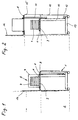
- FIG. 1 shows the side section through a Transfer device 1 according to the invention, which is connected to a purely schematically represented by a dashed line Processing system 2 is coupled.
- the coupling of the Transfer device 1 to the processing system using conventional fasteners (not shown), for example by means of detachable Mounting bolts.
- This box 5 On the loading platform 3 of the transfer device 1 a box 5 containing a magazine 4 is placed.
- This box 5 is preferred as a standardized SMIF (Standard Mechanical Interface). Such boxes will be used for the reception of wafers, which up to Completion of the manufacturing or Machining process processed and transported under clean room conditions Need to become.
- This box 5 has a bottom 6 and one Hood 7 on. The bottom 6 and the hood 7 are in closed state with each other via a releasable Locking mechanism connected. After putting on the Box 5 on the platform 3 is the edge of the hood 7 with the Frame 8 of the platform 3 connected and the Locking mechanism released from base 6 and hood 7. According to the invention, the frame 8 can now be used together with the hood 7 are raised upwards, the bottom 6 and thus the magazine 4 on it Base plate 9 of the platform 3 in the current position remain, as shown in Figure 2.
- SMIF Standard Mechanical Interface
- the lifting takes place, for example, by means of a in a Guide rail 10 vertically slidably mounted Lifting rod 11, which is connected to the frame 8.
- the lifting rod 11 is preferably driven by means of a servo motor 12 which on the housing frame 13 of the Reloading device 1 is arranged.
- the transfer device 1 has in the lower area around the Housing frame 13 on a housing wall 14.
- the housing wall 14 telescopically enclosing cover 15 arranged, which against the processing system 2 one Has passage opening so that the magazine 4 from the Transfer device 1 to the receiving area of the Processing plant 2 can be transported. So that Opening of the receiving area of the processing system 2 also in the loading position shown in Figure 1 Is closed on the outside, there is another on the frame 8 Cover plate 16 arranged, which is from the platform 3rd extends upwards and the said opening of the Coverage area in this position.
- the advantage of this solution according to the invention lies especially in that compared to the input known solutions mentioned after loading the Transfer device 1 only a single lifting operation is necessary to use the magazine 4 immediately thereafter a gripping device and the Feed processing system. On the one hand, this leads to a shorter transfer time, resulting in a higher Processing rate of the wafers leads to lower ones Production costs with higher throughput. On the other hand the lower movements also lead to less Wear and a lower susceptibility to failure of the Reloading device 1. Finally, the ergonomics and fully meets the clean room requirements. Likewise is advantageous that the magazine 4 with the wafers Process is practically not moved, which makes any Damage due to vibrations when lifting and Lowering of the entire box 5 practically completely avoided can be.
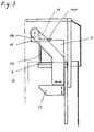
- Transfer device 1 can be particularly advantageous Gripping device likewise designed according to the invention 17, as shown schematically in Figure 3.
- this figure is Illustration of the lid 7 of the box 3 omitted.
- gripping device 17 consists of a Base body 18, which is preferably on both sides in one Cantilever arm 19 is rotatably mounted, and thereof outstanding, preferably at right angles to each other arranged holding fingers 20, 21 and stop element 22.
- cantilever arms 19 There are preferably two, on both sides of the magazine 4 arranged cantilever arms 19 are provided. These extension arms are mounted horizontally on a bracket 23, which in turn can be moved vertically, for example the guide rail 10 is arranged. The Movement directions are shown in the figure by arrows on the Console 23 resp. indicated on the boom arm 19.
- the cantilever arm 19 or. the console 23 moves or been postponed to that the holding fingers 20, 21 laterally engage with the magazine reach.
- the stop element 22 arrives the front, open side of the magazine 4 with the edges of the wafers stacked in it.
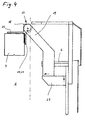
- the magazine 4 by moving the console 23 and the cantilever arms 19 are lifted off the floor 6 and the Loading space of the processing system 2 are fed (by the dash-dotted line shown), as in Figure 4 shown.
- the base body 18 of the Gripping device 17 are preferably pivoted through 90 °, to the magazine 4 in the required position and orientation position.
- the wafers can be conventional means of transport, such as parallel mutually arranged roles (not shown) for which Processing within the processing system 2 from the Magazine 4 are lifted out and then again be fed.
- the return of magazine 4 to Bottom 6 is finally done in the opposite way previously described.
- FIG Gripping device 17 of the transfer device 1 is shown.
- the two holding fingers 20, 21 are pulled out in engagement with the magazine 4 standing bearing shown.
- it can Magazine 4 moved by the boom arms 19. by rotate the base body 18 are pivoted. So that in Magazine 4 stacked wafers do not fall out or become can move, is further the stop element 22nd available, which against the open side of the magazine 4 the edges of the wafers are brought to a stop and this thus fixed in their position. It is also advantageous that the wafers are not affected by vibrations, which by the movement of the cantilever arms 19 and.
- the inventive Gripping device 17 is particularly advantageous for fast movements, what besides the simplified Sequence of movements of the platform 3 of the transfer device 1 with to an increase in the transfer speed and thus to leads to an increase in the productivity of the device.
- the holding fingers 20 and 21 are on the side slidable, as particularly clearly from the Sectional view of the base body 18 in FIG. 6 emerges, resp. like the stock shown in dashed lines the holding fingers 20, 21 in Figure 5 shows.
- This shift is preferably effected by means of a pneumatic cylinder 24, which are arranged in the base body 18.
- pistons 25 are arranged, which with the holding fingers 20 and 21 are connected and the movement transferred to this.
- the pneumatic control allows very fast movements and strong holding forces for magazine 4.
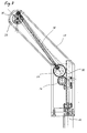
- FIG. 7 shows the longitudinal section through a cantilever arm 19 shown in a preferred embodiment.
- this Embodiment is the rotary movement of the base body 17th not carried out by its own drive, but via Gears 26, 27 and a rod 28 on the axis 29 of the Base body 17 takes place.
- the gear 26 engages in this a rack 30 located on the guide rail 10 on and is at a vertical shift of the Extension arms 19 rotated relative to the guide rail 10.
- the rotary movement is via the further gear 27 and Rod 28 transferred to the axis 29 of the base body 17 and pivots this.
- This is suitable also any other known mechanical transmission of a translatory movement into a rotary movement.
- the drive advantageously only has to be in one of the two Extension arms 19 may be present. Through this configuration will advantageously provide an additional Drive means, for example an additional one Drive motor, for the rotary movement of the gripping device 17 avoided.
- the console 23 is preferably turned on Servo motor used.
- Such engines have a for this application ideal behavior based on the movement on the one hand very precise and always the same Position can be set and on the other hand a slowly increasing acceleration and deceleration of the Movement can be adjusted. This will make jerky Movements prevent the vibration of the wafer in the Can cause magazine 4, which are not wanted.
- the vertical movement of console 23 and Frame 6 generated by the same drive motor, which for the corresponding movement in each case in the drive train is coupled.
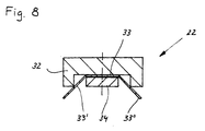
- FIG. 8 is the cross section through the Stop element 22, as in Figure 5 in the view shown, shown.
- It is preferably one Groove having rod 32 formed, in which one of a flat band 33 made of an elastic material is attached.
- the attachment takes place, for example by means of a fastening band 34 which is passed through the band 33 screwed through to the rod 32, for example can be.
- the two side edges 33 'and 33' 'of flat ribbon 33 in protruding outward from the rod at an angle bent out. This allows the two edges 33 'and 33' 'in advantageously with the edges of the stacked wagons be brought to a stop.
- the stop element 22 is thereby advantageously movable independently Base body 18 arranged.
- the transfer device 1 is shown in the Embodiment as a single device for loading and Unloading a single box 5 shown.
- the Design of the device according to the invention is suitable but preferably also for simultaneous loading and Unload multiple boxes 5.
- the Reloading device 1 made wider and parallel next to each other several platforms 6 with several Gripping devices 17 arranged in a housing.
- a single drive motor 12 can then advantageously be used for the lifting movements of several brackets 23 and frames 8 can be used by coupling the powertrains will.
Landscapes
- Engineering & Computer Science (AREA)
- Physics & Mathematics (AREA)
- Condensed Matter Physics & Semiconductors (AREA)
- General Physics & Mathematics (AREA)
- Manufacturing & Machinery (AREA)
- Computer Hardware Design (AREA)
- Microelectronics & Electronic Packaging (AREA)
- Power Engineering (AREA)
- Container, Conveyance, Adherence, Positioning, Of Wafer (AREA)
Abstract
Description
Die vorliegende Erfindung betrifft eine Umladevorrichtung für Wafer nach dem Oberbegriff von Anspruch 1 sowie ein Verfahren zum Betrieb einer solchen Umladevorrichtung.The present invention relates to a transfer device for wafers according to the preamble of claim 1 and a Method for operating such a transfer device.
Die Beschickung von Wafer-Bearbeitungsanlagen mit Wafern erfolgt herkömmlicherweise unter Verwendung von Behältern in Form von genormten Boxen. Derartige Boxen werden in Fachkreisen mit SMIF (Standard Mechanical Interface) bezeichnet. In diesen Boxen sind in der Regel eine Vielzahl von Wafern, d.h. runden Halbleiterplatten, in einem Magazin gestapelt aufbewahrt, wobei die Boxen beispielsweise einen abnehmbaren Deckel in Form einer Haube aufweisen. Die verschlossenen Boxen werden zu einer Umladevorrichtung transportiert, in welcher sie unter Einhaltung von Reinraumbedingungen geöffnet werden und die Wafer der Bearbeitungsanlage zugeführt werden. Nach der Bearbeitung der Wafer werden diese in die Haltevorrichtung der Box zurücktransportiert und die Box wird geschlossen. Anschliessend können die Boxen von der Umladevorrichtung weitertransportiert werden.The loading of wafer processing systems with wafers is conventionally done using containers in the form of standardized boxes. Such boxes are in Specialist groups with SMIF (Standard Mechanical Interface) designated. There are usually a large number in these boxes of wafers, i.e. round semiconductor plates, in a magazine stored stacked, the boxes for example one have a removable cover in the form of a hood. The locked boxes become a reloading device transported, in which they comply with Clean room conditions are opened and the wafers Processing system are fed. After editing the wafers will place them in the holder of the box transported back and the box is closed. The boxes can then be reloaded to be transported further.
Die Boxen werden der Umladevorrichtungen herkömmlicherweise häufig manuell zu- resp. weggeführt, d.h. der Ergonomie dieser Umladevorrichtungen kommt eine grosse Bedeutung zu. Insbesondere ist in der Regel die Höhe der Zufuhr- resp. Wegführebene für die Bedienung durch den Menschen vorgegeben. The boxes are traditionally used for reloading often manually or led away, i.e. ergonomics these reloading devices are of great importance. In particular, the amount of the supply or. Guide level for human operation given.
Vielfach muss bei derartigen herkömmlichen Boxen, bei welchen die Wafer horizontal im Magazin gelagert sind, und welche durch einen in vertikaler Richtung nach oben abnehmbaren, haubenförmigen Deckel verschlossen sind, vor dem eigentlichen Bearbeitungsvorgang in der Bearbeitungsanlage noch eine Schwenkbewegung der Wafer erfolgen, bevor diese beispielsweise in vertikaler Lage der Bearbeitungsanlage zugeführt werden können.In many cases with such conventional boxes which the wafers are stored horizontally in the magazine, and which by going up in a vertical direction removable, hood-shaped lids are closed the actual machining process in the Processing system still a swivel movement of the wafer take place before this, for example, in the vertical position of the Processing system can be fed.
Es sind nun Umladevorrichtungen für derartige Wafer-Boxen bekannt, bei welchen die Boxen auf der Beschickungsebene auf eine vertikal verfahrbare Beschickungsplattform aufgesetzt werden. Anschliessend wird diese Beschickungsplattform zusammen mit der Box angehoben und danach die Verschlussmittel des Deckels der Box gelöst. Danach wird der Teil der Beschickungsplattform, auf welchem der Boden mit dem Magazin aufliegt, wieder abgesenkt, wobei der Deckel auf dem Rahmen der Beschickungsplattform in der angehobenen Stellung verbleibt. Mittels Greifmitteln kann nun das Magazin zusammen mit den Wafern ergriffen, verschwenkt und der Bearbeitungsanlage in vertikaler Ausrichtung zugeführt werden. In umgekehrter Weise erfolgt schliesslich die Rückführung der bearbeiteten Wafer in das Magazin, welches danach zusammen mit dem Boden der Box wieder angehoben und in den Deckel verfahren wird. Nach dem Verriegeln der Verschlussmittel zwischen dem Boden und Deckel wird die gesamte Beschickungsplattform zusammen mit der Box wieder auf die Beschickungsebene abgesenkt kann der Umladevorrichtung entnommen werden. Durch die vielen Bewegungen benötigen diese Umladevorrichtungen einerseits eine beträchtliche Zeit, um den Be- und Entladevorgang durchzuführen und andererseits werden auch grosse Massen bewegt, was einen hohen Antriebsenergiebedarf verursacht und auch zu einer Verlangsamung des ganzen Prozesses beiträgt.There are now reloading devices for such wafer boxes known, where the boxes on the loading level on a vertically movable loading platform be put on. Then it becomes Loading platform along with the box raised and then the closure means of the lid of the box released. Then the part of the loading platform on which the floor with the magazine rests, lowered again, whereby the lid on the frame of the loading platform in the raised position remains. By means of gripping means now grabbed the magazine along with the wafers, pivoted and the processing system in vertical Alignment can be fed. Conversely finally the return of the processed wafers to the Magazine, which is then together with the bottom of the box is raised again and moved into the lid. After this Lock the locking means between the floor and The lid will cover the entire loading platform together with the box can be lowered back to the loading level Reloading device can be removed. Through the many Movements need these reloading devices on the one hand a considerable amount of time to complete the loading and unloading process perform and on the other hand also large masses moves, which causes a high drive energy requirement and also to slow down the whole process contributes.
Die Aufgabe der vorliegenden Erfindung bestand nun darin, eine Umladevorrichtung für in derartigen Boxen gelagerte Wafer zu finden, welche diesen Prozess schnell, einfach und zuverlässig durchführen kann. Gleichzeitig sollen selbstverständlich die ergonomischen Aspekte berücksichtigt werden und die erforderlichen Reinraumbedingungen eingehalten werden.The object of the present invention was now to a transfer device for those stored in such boxes Finding wafers that make this process quick, easy and can perform reliably. At the same time naturally the ergonomic aspects are taken into account and the necessary clean room conditions be respected.
Diese Aufgabe wird durch die erfindungsgemässe Vorrichtung mit den kennzeichnenden Merkmalen nach Anspruch 1 gelöst.This object is achieved by the device according to the invention solved with the characterizing features of claim 1.
Durch den im Vergleich mit der eingangs genannten bekannten Umladevorrichtung vereinfachten Bewegungsablauf für das Öffnen der Box und das Ergreifen und Transportieren des Magazins mit den Wafern wird vorteilhafterweise stark verkürzte Bewegungszeit erreicht, was zu kürzeren Bearbeitungszeiten der Wafer und damit zu grösseren Bearbeitungsdurchsätzen führt. Ebenfalls weist eine derartige erfindungsgemässe Vorrichtung eine höhere Lebensdauer und kleinere Verschleissanfälligkeit auf, was zu einer grösseren Wirtschaftlickkeit im Vergleich zu herkömmlichen Vorrichtungen führt.By the known in comparison with the aforementioned Reloading device simplified movement for that Open the box and grab and transport the Magazine with the wafers is advantageously strong shortened movement time reached, resulting in shorter Processing times of the wafers and thus longer ones Processing throughput leads. Also has one such a device according to the invention a higher Lifespan and minor susceptibility to wear on what to a greater economy compared to leads conventional devices.
Weiter bevorzugte Ausführungsformen der Erfindung ergeben
sich aus den Merkmalen der weiteren Ansprüche 2 bis 12. Further preferred embodiments of the invention result
from the features of
Insbesondere die Kombination des vereinfachten Bewegungsablaufes zusammen mit der bevorzugten Ausführungsform der Greifmittel erlaubt sehr hohe Be- und Entladegeschwindigkeiten der Boxen. Auch bewirkt insbesondere das Vorsehen von zwei Auslegearmen der Greifvorrichtung eine zusätzliche Stabilität beim Greif- und Transportvorgang, was sich auch in einer hohen Präzision der Positionierung des Magazins niederschlägt.In particular, the combination of the simplified Movement along with the preferred one Embodiment of the gripping means allows very high loading and Unloading speeds of the boxes. Also causes in particular the provision of two extension arms of the Gripping device an additional stability when gripping and Transport process, which can also be seen in a high Precision of the positioning of the magazine
Erfindungsgemäss wird weiter ein Verfahren zum Be- und
Entladen von Wafern nach Anspruch 13 oder 14 vorgeschlagen.According to the invention, a method for loading and
Unloading wafers according to
Ein Ausführungsbeispiel der vorliegenden Erfindung wird
nachstehend anhand von Zeichnungen noch näher erläutert. Es
zeigen
Figur 1 zeigt den seitlichen Schnitt durch eine
erfindungsgemässe Umladevorrichtung 1, welche an eine rein
schematisch durch eine gestrichelte Linie dargestellte
Bearbeitungsanlage 2 angekoppelt ist. Die Ankoppelung der
Umladevorrichtung 1 an die Bearbeitungsanlage erfolgt
mittels herkömmlicher Befestigungsmittel (nicht
dargestellt), beispielsweise mittels lösbaren
Befestigungsbolzen.Figure 1 shows the side section through a
Transfer device 1 according to the invention, which is connected to a purely
schematically represented by a dashed
Auf die Beschickungsplattform 3 der Umladevorrichtung 1 ist
eine ein Magazin 4 enthaltende Box 5 aufgelegt. Diese Box 5
ist vorzugsweise als standardisierte SMIF (Standard
Mechanical Interface) ausgeführt. Derartige Boxen werden
für die Aufnahme von Wafer verwendet, welche bis zum
Abschluss der Herstellungs- resp. Bearbeitungsprozesses
unter Reinraumbedingungen bearbeitet und transportiert
werden müssen. Diese Box 5 weist einen Boden 6 und eine
Haube 7 auf. Der Boden 6 und die Haube 7 sind im
verschlossenen Zustand miteinander über einen lösbaren
Verriegelungsmechanismus verbunden. Nach dem Aufsetzen der
Box 5 auf die Plattform 3 wird der Rand der Haube 7 mit dem
Rahmen 8 der Plattform 3 verbunden und der
Verriegelungsmechanismus von Boden 6 und Haube 7 gelöst.
Damit kann nun erfindungsgemäss der Rahmen 8 zusammen mit
der Haube 7 nach oben angehoben werden, wobei der Boden 6
und damit das darauf befindliche Magazin 4 auf der
Bodenplatte 9 der Plattform 3 in der jetzigen Position
verbleiben, wie in Figur 2 dargestellt.On the
Das Anheben erfolgt beispielsweise mittels einer in einer
Führungsschiene 10 vertikal verschiebbar gelagerten
Hebestange 11, welche mit dem Rahmen 8 verbunden ist.
Angetrieben wird die Hebestange 11 vorzugsweise mittels
eines Servomotors 12, welcher am Gehäuserahmen 13 der
Umladevorrichtung 1 angeordnet ist.The lifting takes place, for example, by means of a in a
Die Umladevorrichtung 1 weist im unteren Bereich um den
Gehäuserahmen 13 eine Gehäusewandung 14 auf. Am beweglichen
Rahmen 8 ist ebenfalls eine, die Geäusewandung 14
teleskopartig umschliessende Abdeckung 15 angeordnet,
welche gegen die Bearbeitungsanlage 2 hin eine
Durchlassöffnung aufweist, damit das Magazin 4 von der
Umladevorrichtung 1 zum Aufnahmebereich der
Bearbeitungsanlage 2 transportiert werden kann. Damit die
Öffnung des Aufnahmebereichs der Bearbeitungsanlage 2 auch
in der in Figur 1 dargestellten Beschickungsposition nach
Aussen geschlossen ist, ist am Rahmen 8 weiter eine
Abdeckplatte 16 angeordnet, welche sich von der Plattform 3
aus nach oben erstreckt und die genannte Öffnung des
Aufnahmebereiches in dieser Stellung abdeckt. The transfer device 1 has in the lower area around the
Der Vorteil dieser erfindungsgemässen Lösung liegt
insbesondere darin, dass im Vergleich zu den Eingangs
genannten bekannten Lösungen nach dem Beschicken der
Umladevorrichtung 1 nur noch ein einziger Hubvorgang
notwendig ist, um danach unmittelbar das Magazin 4 mittels
einer Greifeinrichtung zu erfassen und der
Bearbeitungsanlage zuzuführen. Dies führt einerseits zu
einer kürzeren Umladezeit, was zu einer höheren
Bearbeitungsrate der Wafer führt und damit auch zu tieferen
Produktionskosten bei grösserem Durchsatz. Andererseits
führen die geringeren Bewegungsabläufe auch zu weniger
Verschleiss und einer geringeren Störungsanfälligkeit der
Umladevorrichtung 1. Schliesslich werden die Ergonomie- und
die Reinraumanforderungen vollumfänglich erfüllt. Ebenfalls
ist von Vorteil, dass das Magazin 4 mit den Wafern beim
Vorgang praktisch nicht bewegt wird, wodurch allfällige
Beschädigungen infolge von Vibrationen beim Hochheben und
Absenken der gesamten Box 5 praktisch vollständig vermieden
werden können.The advantage of this solution according to the invention lies
especially in that compared to the input
known solutions mentioned after loading the
Transfer device 1 only a single lifting operation
is necessary to use the
Aufgrund der erfindungsgemässen Ausführung der
Umladevorrichtung 1 lässt sich besonders vorteilhaft ein
ebenfalls erfindungsgemäss ausgestaltete Greifvorrichtung
17 einsetzen, wie schematisch in Figur 3 dargestellt ist.
Der Übersichtlichkeit halber ist in dieser Figur die
Darstellung des Deckels 7 der Box 3 weggelassen. Die
Greifvorrichtung 17 besteht erfindungsgemäss aus einem
Grundkörper 18, welcher vorzugsweise beidseitig in einem
Auslegerarm 19 drehbar gelagert angeordnet ist, und davon
herausragenden, vorzugsweise im rechten Winkel zueinaner
angeordneten Haltefingern 20, 21 und Anschlagselement 22.Due to the inventive execution of
Transfer device 1 can be particularly advantageous
Gripping device likewise designed according to the
Vorzugsweise sind zwei, beidseits des Magazins 4
angeordnete Auslegerarme 19 vorgesehen. Diese Auslegearme
sind horizontal verschiebbar auf einer Konsole 23 gelagert,
welche ihrerseits vertikal verschiebbar beispielsweise an
der Führungsschiene 10 angeordnet ist. Die
Bewegungsrichtungen sind in der Figur durch Pfeile an der
Konsole 23 resp. am Auslegerarm 19 angedeutet.There are preferably two, on both sides of the
In der dargestellten Position ist der Auslegerarm 19 resp.
die Konsole 23 derart bewegt resp. verschoben worden, dass
die Haltefinger 20, 21 seitlich mit dem Magazin in Eingriff
gelangen. Gleichzeitig gelangt das Anschlagselement 22 an
der vorderen, offenen Seite des Magazins 4 mit den Rändern
der darin gestapelten Wafern in Anschlag.In the position shown, the
Nun kann das Magazin 4 durch Verfahren der Konsole 23 und
der Auslegerarme 19 vom Boden 6 abgehoben werden und dem
Beladeraum der Bearbeitungsanlage 2 zugeführt werden (durch
die strichpunktierte Linie dargestellt), wie in Figur 4
dargestellt. Ebenfalls kann nun der Grundkörper 18 der
Greifvorrichtung 17 vorzugsweise um 90° verschwenkt werden,
um das Magazin 4 in die geforderte Lage und Ausrichtung zu
positionieren. In dieser Lage können die Wafer mittels
herkömmlicher Transportmitteln, wie beispielsweise parallel
zueinander angeordnete Rollen (nicht dargestellt), für die
Bearbeitung innerhalb der Bearbeitungsanlage 2 aus dem
Magazin 4 herausgehoben werden und danach diesem wieder
zugeführt werden. Die Rückführung des Magazins 4 auf den
Boden 6 erfolgt schliesslich in umgekehrter Weise wie
vorgängig beschrieben.Now the
In Figur 5 ist die Vorderansicht des Bereichs der
Greifvorrichtung 17 der Umladevorrichtung 1 dargestellt.
Klar erkennbar ist hier die beidseitige Lagerung der
Grundkörpers 18 in den beiden seitlich des Magazins 4
angeordneten Auslegerarme 19. Die beiden Haltefinger 20, 21
sind ausgezogen in der mit dem Magazin 4 in Eingriff
stehenden Lager dargestellt. In dieser Lage kann das
Magazin 4 durch die Auslegerarme 19 bewegt resp. durch
drehen des Grundkörpers 18 verschwenkt werden. Damit die im
Magazin 4 gestapelten Wafer nicht herausfallen oder sich
verrücken können, ist weiter das Anschlagselement 22
vorhanden, welches gegen die offene Seite des Magazins 4 an
die Ränder der Wafer in Anschlag gebracht wird und diese
damit in ihrer Lage fixiert. Vorteilhaft ist dabei auch,
dass sich die Wafer auch nicht durch Erschütterungen,
welche durch die Bewegung der Auslegerarme 19 resp. beim
Drehen des Grundkörpers 19 auftreten könnten, bewegt werden
können. Solche Bewegungen können zu störenden
Klappergeräuschen führen. Die erfindungsgemässe
Greifvorrichtung 17 eignet sich besonders vorteilhaft für
schnelle Bewegungen, was neben dem vereinfachten
Bewegungsablauf der Plattform 3 der Umladevorrichtung 1 mit
zu einer Steigerung der Umladegeschwindigkeit und damit zu
einer Steigerung der Produktivität der Vorrichtung führt.5 is the front view of the area of FIG
Um die Greifvorrichtung 17 überhaupt an das Magazin 4 in
Anlage zu bringen, sind die Haltefinger 20 und 21 seitlich
verschiebbar, wie besonders deutlich aus der
Schnittdarstellung des Grundkörpers 18 in Figur 6
hervorgeht, resp. wie die gestrichtelt dargestellte Lager
der Haltefinger 20, 21 in Figur 5 zeigt. Diese Verschiebung
wird vorzugsweise mittels Pneumatikzylinder 24 bewirkt,
welche im Grundkörper 18 angeordnet sind. In diesen
Pneumatikzylindern 24 sind Kolben 25 angeordnet, welche mit
den Haltefingern 20 und 21 verbunden sind und die Bewegung
auf diese übertragen. Die pneumatische Ansteuerung erlaubt
sehr schnelle Bewegungsabläufe und starke Haltekräfte für
das Magazin 4.To the
In Figur 7 ist der Längsschnitt durch einen Auslegerarm 19
in bevorzugter Ausführungsform dargestellt. In dieser
Ausführungsform wird die Drehbewegung des Grundkörpers 17
nicht durch einen eigenen Antrieb ausgeführt, sondern über
Zahnräder 26, 27 und einer Stange 28 auf die Achse 29 des
Grundkörpers 17 erfolgt. Das Zahnrad 26 greift hierbei in
eine an der Führungsschiene 10 befindliche Zahnstange 30
ein und wird bei einer vertikalen Verschiebung des
Auslegearmes 19 gegenüber der Führungsschiene 10 verdreht.
Die Drehbewegung wird über das weitere Zahnrad 27 und die
Stange 28 zur Achse 29 des Grundkörpers 17 übertragen und
verschwenkt diesen. Selbstverständlich eignet sich hierfür
auch jede andere bekannte mechanische Uebertragung einer
translatorischen Bewegung in eine Drehbewegung.
Vorteilhafterweise muss der Antrieb nur in einem der beiden
Auslegearme 19 vorhanden sein. Durch diese Ausgestaltung
wird vorteilhafterweise das Vorsehen eines zusätzliches
Antriebsmittel, beispielsweise eines zusätzlichen
Antriebsmotors, für die Drehbewegung der Greifvorrichtung
17 vermieden.7 shows the longitudinal section through a
Als Antriebsmittel für die Hubbewegung des Rahmens 6 resp.
der Konsole 23 wird erfindungsgemäss vorzugsweise ein
Servomotor eingesetzt. Derartige Motoren weisen ein für
diese Anwendung ideales Verhalten auf, indem die Bewegung
einerseits sehr präzise und auf immer wieder dieselbe
Position eingestellt werden kann und andererseits eine
langsam ansteigende Beschleunigung und Verlangsamung der
Bewegung eingestellt werden kann. Dadurch werden ruckartige
Bewegungen verhindert, welche Erschütterungen der Wafer im
Magazin 4 hervorrufen könnten, welche nicht erwünscht sind.
Vorzugsweise wird die vertikale Bewegung von Konsole 23 und
Rahmen 6 durch denselben Antriebsmotor erzeugt, welche für
die entsprechende Bewegung jeweils in den Antriebsstrang
eingekoppelt wird.As a drive for the lifting movement of the
In Figur 8 ist schliesslich noch der Querschnitt durch das
Anschlagelement 22, wie in Figur 5 in der Ansicht
dargestellt, gezeigt. Vorzugsweise ist es aus einem eine
Nut aufweisenden Stange 32 gebildet, in welcher ein aus
einem elastischen Material bestehendes, flaches Band 33
befestigt ist. Die Befestigung erfolgt beispielsweise
mittels eines Befestigungsbandes 34, welches durch das Band
33 hindurch mit der Stange 32 beispielsweise verschraubt
sein kann. Durch diese Befestigungsart werden die beiden
seitlichen Kanten 33' und 33'' des flachen Bandes 33 in
einem Winkel nach Aussen von der Stange abstehend
ausgebogen. Damit können die beiden Kanten 33' und 33'' in
vorteilhafter Weise mit den Rändern der gestapelten Wager
in Anschlag gebracht werden. Das Anschlagelement 22 ist
dabei vorteilhafterweise eigenständig bewegbar im
Grundkörper 18 angeordnet.Finally, in FIG. 8 is the cross section through the
Die Umladevorrichtung 1 ist in den dargestellten
Ausführungsbeispiel als Einzelvorrichtung zum Be- und
Entladen einer einzelnen Box 5 dargestellt. Die
erfindungsgemässe Ausgestaltung der Vorrichtung eignet sich
aber vorzugsweise auch für das gleichzeitige Be- und
Entladen von mehreren Boxen 5. Hierfür wird die
Umladevorrichtung 1 breiter ausgeführt und parallel
nebeneinander mehrere Plattformen 6 mit mehreren
Greifvorrichtungen 17 in einem Gehäuse angeordnet.
Vorteilhafterweise kann dann ein einzelner Antriebsmotor 12
für die Hubbewegungen auch mehrerer Konsolen 23 und Rahmen
8 verwendet werden, indem die Antriebsstränge gekoppelt
werden.The transfer device 1 is shown in the
Embodiment as a single device for loading and
Unloading a
Claims (14)
Priority Applications (2)
| Application Number | Priority Date | Filing Date | Title |
|---|---|---|---|
| EP97107352A EP0875921A1 (en) | 1997-05-03 | 1997-05-03 | Wafer transfer apparatus |
| US08/892,391 US5975825A (en) | 1997-03-05 | 1997-07-14 | Transfer apparatus for wafers |
Applications Claiming Priority (1)
| Application Number | Priority Date | Filing Date | Title |
|---|---|---|---|
| EP97107352A EP0875921A1 (en) | 1997-05-03 | 1997-05-03 | Wafer transfer apparatus |
Publications (1)
| Publication Number | Publication Date |
|---|---|
| EP0875921A1 true EP0875921A1 (en) | 1998-11-04 |
Family
ID=8226763
Family Applications (1)
| Application Number | Title | Priority Date | Filing Date |
|---|---|---|---|
| EP97107352A Withdrawn EP0875921A1 (en) | 1997-03-05 | 1997-05-03 | Wafer transfer apparatus |
Country Status (2)
| Country | Link |
|---|---|
| US (1) | US5975825A (en) |
| EP (1) | EP0875921A1 (en) |
Families Citing this family (7)
| Publication number | Priority date | Publication date | Assignee | Title |
|---|---|---|---|---|
| US6042324A (en) * | 1999-03-26 | 2000-03-28 | Asm America, Inc. | Multi-stage single-drive FOUP door system |
| DE19916932C1 (en) * | 1999-04-09 | 2000-10-12 | Jenoptik Jena Gmbh | Device for handling an object for loading and unloading a clean room |
| US6736582B1 (en) | 1999-04-09 | 2004-05-18 | Brooks Automation, Inc. | Device for manipulating an object for loading and unloading a clean room |
| EP1193736A1 (en) * | 2000-09-27 | 2002-04-03 | Infineon Technologies SC300 GmbH & Co. KG | Vehicle for transporting a semiconductor device carrier to a semiconductor processing tool |
| US6592318B2 (en) * | 2001-07-13 | 2003-07-15 | Asm America, Inc. | Docking cart with integrated load port |
| WO2006004718A1 (en) | 2004-06-28 | 2006-01-12 | Brooks Automation, Inc. | Non productive wafer buffer module for substrate processing apparatus |
| JP2010132404A (en) * | 2008-12-04 | 2010-06-17 | Muratec Automation Co Ltd | Carrying carriage |
Citations (3)
| Publication number | Priority date | Publication date | Assignee | Title |
|---|---|---|---|---|
| EP0209660A2 (en) * | 1985-07-24 | 1987-01-28 | Hewlett-Packard Company | Apparatus and method for automated cassette handling |
| DE4332657A1 (en) * | 1993-09-27 | 1995-03-30 | Acr Automation In Cleanroom | Device for handling substrates in super-clean rooms and lock arrangement equipped with such a device |
| EP0651429A1 (en) * | 1993-10-29 | 1995-05-03 | Applied Materials, Inc. | Enclosure for load lock interface |
Family Cites Families (7)
| Publication number | Priority date | Publication date | Assignee | Title |
|---|---|---|---|---|
| US4674936A (en) * | 1985-08-26 | 1987-06-23 | Asyst Technologies | Short arm manipulator for standard mechanical interface apparatus |
| US4676709A (en) * | 1985-08-26 | 1987-06-30 | Asyst Technologies | Long arm manipulator for standard mechanical interface apparatus |
| DE3637880C2 (en) * | 1986-11-06 | 1994-09-01 | Meissner & Wurst | Transportable container for handling semiconductor elements during their manufacture as well as methods for the particle-free delivery of products |
| US5169272A (en) * | 1990-11-01 | 1992-12-08 | Asyst Technologies, Inc. | Method and apparatus for transferring articles between two controlled environments |
| JPH05146984A (en) * | 1991-07-08 | 1993-06-15 | Murata Mach Ltd | Robot for handling wafer cassette |
| DE4425208C2 (en) * | 1994-07-16 | 1996-05-09 | Jenoptik Technologie Gmbh | Device for coupling loading and unloading devices with semiconductor processing machines |
| US5674039A (en) * | 1996-07-12 | 1997-10-07 | Fusion Systems Corporation | System for transferring articles between controlled environments |
-
1997
- 1997-05-03 EP EP97107352A patent/EP0875921A1/en not_active Withdrawn
- 1997-07-14 US US08/892,391 patent/US5975825A/en not_active Expired - Lifetime
Patent Citations (3)
| Publication number | Priority date | Publication date | Assignee | Title |
|---|---|---|---|---|
| EP0209660A2 (en) * | 1985-07-24 | 1987-01-28 | Hewlett-Packard Company | Apparatus and method for automated cassette handling |
| DE4332657A1 (en) * | 1993-09-27 | 1995-03-30 | Acr Automation In Cleanroom | Device for handling substrates in super-clean rooms and lock arrangement equipped with such a device |
| EP0651429A1 (en) * | 1993-10-29 | 1995-05-03 | Applied Materials, Inc. | Enclosure for load lock interface |
Also Published As
| Publication number | Publication date |
|---|---|
| US5975825A (en) | 1999-11-02 |
Similar Documents
| Publication | Publication Date | Title |
|---|---|---|
| EP3579987B1 (en) | Bending tool storage device and method for feeding a press brake | |
| EP1016497B1 (en) | Machine tool | |
| DE102015206914A1 (en) | machine tool | |
| DE1948425B2 (en) | Storage and retrieval device for stacking plates at freely selectable positions on the stack | |
| DE2247703A1 (en) | CONVEYOR DEVICE FOR PICKING UP AND DISPENSING PARTS | |
| EP1114440A1 (en) | Device and method for handling individual wafers | |
| DE4201289C2 (en) | Device for handling workpieces | |
| DE69200171T2 (en) | Device for changing multi-purpose container carriers. | |
| DE69902974T2 (en) | Device for storing and changing tools of a machine tool and working method of such a device | |
| DE112016001704T5 (en) | Workpiece attaching / removing device | |
| DE19921072A1 (en) | Device for handling substrates inside and outside a high-purity work room | |
| EP0875921A1 (en) | Wafer transfer apparatus | |
| DE19823933B4 (en) | Linear movement device | |
| DE69219069T2 (en) | Machine for printed circuits with a tool changer | |
| DE4236416A1 (en) | ||
| DE68916205T2 (en) | Automatic loading mechanism. | |
| DE9014123U1 (en) | Device for aligning, lifting and pivoting a container relative to a vertical opening | |
| DE69103679T2 (en) | Device for transporting single crystal rods. | |
| DE68902735T2 (en) | DEVICE FOR PUTTING A FILM INTO A MOLDING MACHINE. | |
| EP1621284A1 (en) | Workpiece changing device for machine tools | |
| DE69016780T2 (en) | DEVICE FOR THE TRANSFER OF A WORKPIECE. | |
| DE2045507A1 (en) | Device for inserting the pointers of clocks or other measuring devices | |
| DE102016120151A1 (en) | Method and machine tool for processing plate-shaped workpieces, in particular sheets | |
| DE102019117026B4 (en) | Transport system | |
| DE3337374A1 (en) | Device for the mechanical stacking and/or unstacking of pallets or the like |
Legal Events
| Date | Code | Title | Description |
|---|---|---|---|
| PUAI | Public reference made under article 153(3) epc to a published international application that has entered the european phase |
Free format text: ORIGINAL CODE: 0009012 |
|
| 17P | Request for examination filed |
Effective date: 19980714 |
|
| AK | Designated contracting states |
Kind code of ref document: A1 Designated state(s): CH DE FR GB IE IT LI NL SE |
|
| AKX | Designation fees paid |
Free format text: CH DE FR GB IE IT LI NL SE |
|
| RAP1 | Party data changed (applicant data changed or rights of an application transferred) |
Owner name: TEC-SEM AG |
|
| STAA | Information on the status of an ep patent application or granted ep patent |
Free format text: STATUS: THE APPLICATION IS DEEMED TO BE WITHDRAWN |
|
| 18D | Application deemed to be withdrawn |
Effective date: 20011201 |