EP0875921A1 - Appareil de transfert pour galettes - Google Patents
Appareil de transfert pour galettes Download PDFInfo
- Publication number
- EP0875921A1 EP0875921A1 EP97107352A EP97107352A EP0875921A1 EP 0875921 A1 EP0875921 A1 EP 0875921A1 EP 97107352 A EP97107352 A EP 97107352A EP 97107352 A EP97107352 A EP 97107352A EP 0875921 A1 EP0875921 A1 EP 0875921A1
- Authority
- EP
- European Patent Office
- Prior art keywords
- transfer device
- magazine
- box
- gripping
- frame
- Prior art date
- Legal status (The legal status is an assumption and is not a legal conclusion. Google has not performed a legal analysis and makes no representation as to the accuracy of the status listed.)
- Withdrawn
Links
Images

Classifications
-
- H—ELECTRICITY
- H01—ELECTRIC ELEMENTS
- H01L—SEMICONDUCTOR DEVICES NOT COVERED BY CLASS H10
- H01L21/00—Processes or apparatus adapted for the manufacture or treatment of semiconductor or solid state devices or of parts thereof
- H01L21/67—Apparatus specially adapted for handling semiconductor or electric solid state devices during manufacture or treatment thereof; Apparatus specially adapted for handling wafers during manufacture or treatment of semiconductor or electric solid state devices or components ; Apparatus not specifically provided for elsewhere
- H01L21/677—Apparatus specially adapted for handling semiconductor or electric solid state devices during manufacture or treatment thereof; Apparatus specially adapted for handling wafers during manufacture or treatment of semiconductor or electric solid state devices or components ; Apparatus not specifically provided for elsewhere for conveying, e.g. between different workstations
- H01L21/67763—Apparatus specially adapted for handling semiconductor or electric solid state devices during manufacture or treatment thereof; Apparatus specially adapted for handling wafers during manufacture or treatment of semiconductor or electric solid state devices or components ; Apparatus not specifically provided for elsewhere for conveying, e.g. between different workstations the wafers being stored in a carrier, involving loading and unloading
- H01L21/67772—Apparatus specially adapted for handling semiconductor or electric solid state devices during manufacture or treatment thereof; Apparatus specially adapted for handling wafers during manufacture or treatment of semiconductor or electric solid state devices or components ; Apparatus not specifically provided for elsewhere for conveying, e.g. between different workstations the wafers being stored in a carrier, involving loading and unloading involving removal of lid, door, cover
-
- Y—GENERAL TAGGING OF NEW TECHNOLOGICAL DEVELOPMENTS; GENERAL TAGGING OF CROSS-SECTIONAL TECHNOLOGIES SPANNING OVER SEVERAL SECTIONS OF THE IPC; TECHNICAL SUBJECTS COVERED BY FORMER USPC CROSS-REFERENCE ART COLLECTIONS [XRACs] AND DIGESTS
- Y10—TECHNICAL SUBJECTS COVERED BY FORMER USPC
- Y10S—TECHNICAL SUBJECTS COVERED BY FORMER USPC CROSS-REFERENCE ART COLLECTIONS [XRACs] AND DIGESTS
- Y10S414/00—Material or article handling
- Y10S414/135—Associated with semiconductor wafer handling
- Y10S414/139—Associated with semiconductor wafer handling including wafer charging or discharging means for vacuum chamber
-
- Y—GENERAL TAGGING OF NEW TECHNOLOGICAL DEVELOPMENTS; GENERAL TAGGING OF CROSS-SECTIONAL TECHNOLOGIES SPANNING OVER SEVERAL SECTIONS OF THE IPC; TECHNICAL SUBJECTS COVERED BY FORMER USPC CROSS-REFERENCE ART COLLECTIONS [XRACs] AND DIGESTS
- Y10—TECHNICAL SUBJECTS COVERED BY FORMER USPC
- Y10S—TECHNICAL SUBJECTS COVERED BY FORMER USPC CROSS-REFERENCE ART COLLECTIONS [XRACs] AND DIGESTS
- Y10S414/00—Material or article handling
- Y10S414/135—Associated with semiconductor wafer handling
- Y10S414/14—Wafer cassette transporting
Definitions
- the present invention relates to a transfer device for wafers according to the preamble of claim 1 and a Method for operating such a transfer device.
- the loading of wafer processing systems with wafers is conventionally done using containers in the form of standardized boxes.
- Such boxes are in Specialist groups with SMIF (Standard Mechanical Interface) designated.
- SMIF Standard Mechanical Interface
- the locked boxes become a reloading device transported, in which they comply with Clean room conditions are opened and the wafers Processing system are fed. After editing the wafers will place them in the holder of the box transported back and the box is closed.
- the boxes can then be reloaded to be transported further.
- the boxes are traditionally used for reloading often manually or led away, i.e. ergonomics these reloading devices are of great importance. In particular, the amount of the supply or. Guide level for human operation given.
- the object of the present invention was now to a transfer device for those stored in such boxes Finding wafers that make this process quick, easy and can perform reliably. At the same time naturally the ergonomic aspects are taken into account and the necessary clean room conditions be respected.
- the combination of the simplified Movement along with the preferred one Embodiment of the gripping means allows very high loading and Unloading speeds of the boxes. Also causes in particular the provision of two extension arms of the Gripping device an additional stability when gripping and Transport process, which can also be seen in a high Precision of the positioning of the magazine
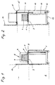
- FIG. 1 shows the side section through a Transfer device 1 according to the invention, which is connected to a purely schematically represented by a dashed line Processing system 2 is coupled.
- the coupling of the Transfer device 1 to the processing system using conventional fasteners (not shown), for example by means of detachable Mounting bolts.
- This box 5 On the loading platform 3 of the transfer device 1 a box 5 containing a magazine 4 is placed.
- This box 5 is preferred as a standardized SMIF (Standard Mechanical Interface). Such boxes will be used for the reception of wafers, which up to Completion of the manufacturing or Machining process processed and transported under clean room conditions Need to become.
- This box 5 has a bottom 6 and one Hood 7 on. The bottom 6 and the hood 7 are in closed state with each other via a releasable Locking mechanism connected. After putting on the Box 5 on the platform 3 is the edge of the hood 7 with the Frame 8 of the platform 3 connected and the Locking mechanism released from base 6 and hood 7. According to the invention, the frame 8 can now be used together with the hood 7 are raised upwards, the bottom 6 and thus the magazine 4 on it Base plate 9 of the platform 3 in the current position remain, as shown in Figure 2.
- SMIF Standard Mechanical Interface
- the lifting takes place, for example, by means of a in a Guide rail 10 vertically slidably mounted Lifting rod 11, which is connected to the frame 8.
- the lifting rod 11 is preferably driven by means of a servo motor 12 which on the housing frame 13 of the Reloading device 1 is arranged.
- the transfer device 1 has in the lower area around the Housing frame 13 on a housing wall 14.
- the housing wall 14 telescopically enclosing cover 15 arranged, which against the processing system 2 one Has passage opening so that the magazine 4 from the Transfer device 1 to the receiving area of the Processing plant 2 can be transported. So that Opening of the receiving area of the processing system 2 also in the loading position shown in Figure 1 Is closed on the outside, there is another on the frame 8 Cover plate 16 arranged, which is from the platform 3rd extends upwards and the said opening of the Coverage area in this position.
- the advantage of this solution according to the invention lies especially in that compared to the input known solutions mentioned after loading the Transfer device 1 only a single lifting operation is necessary to use the magazine 4 immediately thereafter a gripping device and the Feed processing system. On the one hand, this leads to a shorter transfer time, resulting in a higher Processing rate of the wafers leads to lower ones Production costs with higher throughput. On the other hand the lower movements also lead to less Wear and a lower susceptibility to failure of the Reloading device 1. Finally, the ergonomics and fully meets the clean room requirements. Likewise is advantageous that the magazine 4 with the wafers Process is practically not moved, which makes any Damage due to vibrations when lifting and Lowering of the entire box 5 practically completely avoided can be.
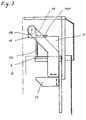
- Transfer device 1 can be particularly advantageous Gripping device likewise designed according to the invention 17, as shown schematically in Figure 3.
- this figure is Illustration of the lid 7 of the box 3 omitted.
- gripping device 17 consists of a Base body 18, which is preferably on both sides in one Cantilever arm 19 is rotatably mounted, and thereof outstanding, preferably at right angles to each other arranged holding fingers 20, 21 and stop element 22.
- cantilever arms 19 There are preferably two, on both sides of the magazine 4 arranged cantilever arms 19 are provided. These extension arms are mounted horizontally on a bracket 23, which in turn can be moved vertically, for example the guide rail 10 is arranged. The Movement directions are shown in the figure by arrows on the Console 23 resp. indicated on the boom arm 19.
- the cantilever arm 19 or. the console 23 moves or been postponed to that the holding fingers 20, 21 laterally engage with the magazine reach.
- the stop element 22 arrives the front, open side of the magazine 4 with the edges of the wafers stacked in it.
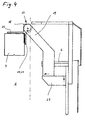
- the magazine 4 by moving the console 23 and the cantilever arms 19 are lifted off the floor 6 and the Loading space of the processing system 2 are fed (by the dash-dotted line shown), as in Figure 4 shown.
- the base body 18 of the Gripping device 17 are preferably pivoted through 90 °, to the magazine 4 in the required position and orientation position.
- the wafers can be conventional means of transport, such as parallel mutually arranged roles (not shown) for which Processing within the processing system 2 from the Magazine 4 are lifted out and then again be fed.
- the return of magazine 4 to Bottom 6 is finally done in the opposite way previously described.
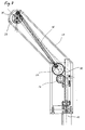
- FIG Gripping device 17 of the transfer device 1 is shown.
- the two holding fingers 20, 21 are pulled out in engagement with the magazine 4 standing bearing shown.
- it can Magazine 4 moved by the boom arms 19. by rotate the base body 18 are pivoted. So that in Magazine 4 stacked wafers do not fall out or become can move, is further the stop element 22nd available, which against the open side of the magazine 4 the edges of the wafers are brought to a stop and this thus fixed in their position. It is also advantageous that the wafers are not affected by vibrations, which by the movement of the cantilever arms 19 and.
- the inventive Gripping device 17 is particularly advantageous for fast movements, what besides the simplified Sequence of movements of the platform 3 of the transfer device 1 with to an increase in the transfer speed and thus to leads to an increase in the productivity of the device.
- the holding fingers 20 and 21 are on the side slidable, as particularly clearly from the Sectional view of the base body 18 in FIG. 6 emerges, resp. like the stock shown in dashed lines the holding fingers 20, 21 in Figure 5 shows.
- This shift is preferably effected by means of a pneumatic cylinder 24, which are arranged in the base body 18.
- pistons 25 are arranged, which with the holding fingers 20 and 21 are connected and the movement transferred to this.
- the pneumatic control allows very fast movements and strong holding forces for magazine 4.
- FIG. 7 shows the longitudinal section through a cantilever arm 19 shown in a preferred embodiment.
- this Embodiment is the rotary movement of the base body 17th not carried out by its own drive, but via Gears 26, 27 and a rod 28 on the axis 29 of the Base body 17 takes place.
- the gear 26 engages in this a rack 30 located on the guide rail 10 on and is at a vertical shift of the Extension arms 19 rotated relative to the guide rail 10.
- the rotary movement is via the further gear 27 and Rod 28 transferred to the axis 29 of the base body 17 and pivots this.
- This is suitable also any other known mechanical transmission of a translatory movement into a rotary movement.
- the drive advantageously only has to be in one of the two Extension arms 19 may be present. Through this configuration will advantageously provide an additional Drive means, for example an additional one Drive motor, for the rotary movement of the gripping device 17 avoided.
- the console 23 is preferably turned on Servo motor used.
- Such engines have a for this application ideal behavior based on the movement on the one hand very precise and always the same Position can be set and on the other hand a slowly increasing acceleration and deceleration of the Movement can be adjusted. This will make jerky Movements prevent the vibration of the wafer in the Can cause magazine 4, which are not wanted.
- the vertical movement of console 23 and Frame 6 generated by the same drive motor, which for the corresponding movement in each case in the drive train is coupled.
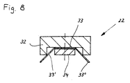
- FIG. 8 is the cross section through the Stop element 22, as in Figure 5 in the view shown, shown.
- It is preferably one Groove having rod 32 formed, in which one of a flat band 33 made of an elastic material is attached.
- the attachment takes place, for example by means of a fastening band 34 which is passed through the band 33 screwed through to the rod 32, for example can be.
- the two side edges 33 'and 33' 'of flat ribbon 33 in protruding outward from the rod at an angle bent out. This allows the two edges 33 'and 33' 'in advantageously with the edges of the stacked wagons be brought to a stop.
- the stop element 22 is thereby advantageously movable independently Base body 18 arranged.
- the transfer device 1 is shown in the Embodiment as a single device for loading and Unloading a single box 5 shown.
- the Design of the device according to the invention is suitable but preferably also for simultaneous loading and Unload multiple boxes 5.
- the Reloading device 1 made wider and parallel next to each other several platforms 6 with several Gripping devices 17 arranged in a housing.
- a single drive motor 12 can then advantageously be used for the lifting movements of several brackets 23 and frames 8 can be used by coupling the powertrains will.
Priority Applications (2)
| Application Number | Priority Date | Filing Date | Title |
|---|---|---|---|
| EP97107352A EP0875921A1 (fr) | 1997-05-03 | 1997-05-03 | Appareil de transfert pour galettes |
| US08/892,391 US5975825A (en) | 1997-03-05 | 1997-07-14 | Transfer apparatus for wafers |
Applications Claiming Priority (1)
| Application Number | Priority Date | Filing Date | Title |
|---|---|---|---|
| EP97107352A EP0875921A1 (fr) | 1997-05-03 | 1997-05-03 | Appareil de transfert pour galettes |
Publications (1)
| Publication Number | Publication Date |
|---|---|
| EP0875921A1 true EP0875921A1 (fr) | 1998-11-04 |
Family
ID=8226763
Family Applications (1)
| Application Number | Title | Priority Date | Filing Date |
|---|---|---|---|
| EP97107352A Withdrawn EP0875921A1 (fr) | 1997-03-05 | 1997-05-03 | Appareil de transfert pour galettes |
Country Status (2)
| Country | Link |
|---|---|
| US (1) | US5975825A (fr) |
| EP (1) | EP0875921A1 (fr) |
Families Citing this family (7)
| Publication number | Priority date | Publication date | Assignee | Title |
|---|---|---|---|---|
| US6042324A (en) * | 1999-03-26 | 2000-03-28 | Asm America, Inc. | Multi-stage single-drive FOUP door system |
| US6736582B1 (en) | 1999-04-09 | 2004-05-18 | Brooks Automation, Inc. | Device for manipulating an object for loading and unloading a clean room |
| DE19916932C1 (de) * | 1999-04-09 | 2000-10-12 | Jenoptik Jena Gmbh | Einrichtung zur Handhabung eines Gegenstandes für die Be- und Entladung eines Reinstraumes |
| EP1193736A1 (fr) * | 2000-09-27 | 2002-04-03 | Infineon Technologies SC300 GmbH & Co. KG | Véhicule pour le transport de conteneur de dispositifs à base de semiconducteur vers une station de traitement de semiconducteur |
| US6592318B2 (en) * | 2001-07-13 | 2003-07-15 | Asm America, Inc. | Docking cart with integrated load port |
| WO2006004718A1 (fr) | 2004-06-28 | 2006-01-12 | Brooks Automation, Inc. | Module tampon de tranche non productive pour appareil de traitement de substrats |
| JP2010132404A (ja) * | 2008-12-04 | 2010-06-17 | Muratec Automation Co Ltd | 搬送台車 |
Citations (3)
| Publication number | Priority date | Publication date | Assignee | Title |
|---|---|---|---|---|
| EP0209660A2 (fr) * | 1985-07-24 | 1987-01-28 | Hewlett-Packard Company | Dispositif et méthode de manipulation automatique d'une cassette |
| DE4332657A1 (de) * | 1993-09-27 | 1995-03-30 | Acr Automation In Cleanroom | Vorrichtung zum Handhaben von Substraten in Reinsträumen und mit einer derartigen Vorrichtung versehene Schleuseneinrichtung |
| EP0651429A1 (fr) * | 1993-10-29 | 1995-05-03 | Applied Materials, Inc. | Enveloppe pour interface de sas de chargement |
Family Cites Families (7)
| Publication number | Priority date | Publication date | Assignee | Title |
|---|---|---|---|---|
| US4674936A (en) * | 1985-08-26 | 1987-06-23 | Asyst Technologies | Short arm manipulator for standard mechanical interface apparatus |
| US4676709A (en) * | 1985-08-26 | 1987-06-30 | Asyst Technologies | Long arm manipulator for standard mechanical interface apparatus |
| DE3637880C2 (de) * | 1986-11-06 | 1994-09-01 | Meissner & Wurst | Transportierbares Behältnis zur Handhabung von Halbleiterelementen während ihrer Herstellung sowie Verfahren zur partikelfreien Übergabe von Produkten |
| US5169272A (en) * | 1990-11-01 | 1992-12-08 | Asyst Technologies, Inc. | Method and apparatus for transferring articles between two controlled environments |
| JPH05146984A (ja) * | 1991-07-08 | 1993-06-15 | Murata Mach Ltd | ウエハカセツト用ハンドリングロボツト |
| DE4425208C2 (de) * | 1994-07-16 | 1996-05-09 | Jenoptik Technologie Gmbh | Einrichtung zur Kopplung von Be- und Entladegeräten mit Halbleiterbearbeitungsmaschinen |
| US5674039A (en) * | 1996-07-12 | 1997-10-07 | Fusion Systems Corporation | System for transferring articles between controlled environments |
-
1997
- 1997-05-03 EP EP97107352A patent/EP0875921A1/fr not_active Withdrawn
- 1997-07-14 US US08/892,391 patent/US5975825A/en not_active Expired - Lifetime
Patent Citations (3)
| Publication number | Priority date | Publication date | Assignee | Title |
|---|---|---|---|---|
| EP0209660A2 (fr) * | 1985-07-24 | 1987-01-28 | Hewlett-Packard Company | Dispositif et méthode de manipulation automatique d'une cassette |
| DE4332657A1 (de) * | 1993-09-27 | 1995-03-30 | Acr Automation In Cleanroom | Vorrichtung zum Handhaben von Substraten in Reinsträumen und mit einer derartigen Vorrichtung versehene Schleuseneinrichtung |
| EP0651429A1 (fr) * | 1993-10-29 | 1995-05-03 | Applied Materials, Inc. | Enveloppe pour interface de sas de chargement |
Also Published As
| Publication number | Publication date |
|---|---|
| US5975825A (en) | 1999-11-02 |
Similar Documents
| Publication | Publication Date | Title |
|---|---|---|
| EP1016497B1 (fr) | Machine-outil | |
| EP3579987B1 (fr) | Magasin d'outils de cintrage et procédé de chargement d'une presse-plieuse | |
| DE1948425B2 (de) | Ein- und Auslagervorrichtung für Stapelplatten an frei wählbaren Stellen des Stapels | |
| DE2247703A1 (de) | Foerdereinrichtung zur aufnahme und abgabe von teilen | |
| EP1616661B1 (fr) | Machine d'usinage avec dispositif de changement de pièces | |
| EP1114440A1 (fr) | Dispositif et procede permettant de manipuler separement des plaquettes | |
| DE4201289C2 (de) | Vorrichtung zur Handhabung von Werkstücken | |
| DE112016001704T5 (de) | Werkstück-Anbringungs-/Entfernungsvorrichtung | |
| DE19921072A1 (de) | Einrichtung zum Handhaben von Substraten innerhalb und außerhalb eines Reinstarbeitsraumes | |
| EP0875921A1 (fr) | Appareil de transfert pour galettes | |
| DE19823933B4 (de) | Lineare Bewegungseinrichtung | |
| DE4236416A1 (fr) | ||
| EP0597868B1 (fr) | Dispositif d'introduction d'objets dans une machine et/ou d'enlevement d'objets d'une machine | |
| DE102016120151A1 (de) | Verfahren und Werkzeugmaschine zum Bearbeiten von plattenförmigen Werkstücken, insbesondere von Blechen | |
| DE2045507A1 (de) | Gerat zum Einsetzen von Zeigern von Uhren oder anderen Messgeraten | |
| DE102019117026B4 (de) | Transportsystem | |
| DE3151244C2 (fr) | ||
| DE4418184C2 (de) | Vorrichtung zur Betätigung einer Abstützung von Containern in Führungsprofilen | |
| DE3231765A1 (de) | Einrichtung zum handhaben von werkstuecktraegern vor bearbeitungsstationen | |
| EP0396997B1 (fr) | Dispositif et moyens pour la formation d'une pile de pièces plates et récipient pour stocker et transporter la pile | |
| DE102020123464A1 (de) | Parallelroboter | |
| DE202023104884U1 (de) | Anlage zur Herstellung von Verpackungen | |
| DE19651934A1 (de) | Transferpresse | |
| EP2062714B1 (fr) | Dispositif d'alimentation pour substrats et dispositif de moulage par injection | |
| DE102012202756B4 (de) | Vorrichtung zur Handhabung von Formteilen aus thermoplastischem Kunststoff |
Legal Events
| Date | Code | Title | Description |
|---|---|---|---|
| PUAI | Public reference made under article 153(3) epc to a published international application that has entered the european phase |
Free format text: ORIGINAL CODE: 0009012 |
|
| 17P | Request for examination filed |
Effective date: 19980714 |
|
| AK | Designated contracting states |
Kind code of ref document: A1 Designated state(s): CH DE FR GB IE IT LI NL SE |
|
| AKX | Designation fees paid |
Free format text: CH DE FR GB IE IT LI NL SE |
|
| RAP1 | Party data changed (applicant data changed or rights of an application transferred) |
Owner name: TEC-SEM AG |
|
| STAA | Information on the status of an ep patent application or granted ep patent |
Free format text: STATUS: THE APPLICATION IS DEEMED TO BE WITHDRAWN |
|
| 18D | Application deemed to be withdrawn |
Effective date: 20011201 |