EP0875678A2 - Oil pump control valve - Google Patents
Oil pump control valve Download PDFInfo
- Publication number
- EP0875678A2 EP0875678A2 EP98201366A EP98201366A EP0875678A2 EP 0875678 A2 EP0875678 A2 EP 0875678A2 EP 98201366 A EP98201366 A EP 98201366A EP 98201366 A EP98201366 A EP 98201366A EP 0875678 A2 EP0875678 A2 EP 0875678A2
- Authority
- EP
- European Patent Office
- Prior art keywords
- port
- oil
- oil pump
- sub
- control
- Prior art date
- Legal status (The legal status is an assumption and is not a legal conclusion. Google has not performed a legal analysis and makes no representation as to the accuracy of the status listed.)
- Granted
Links
- 238000010586 diagram Methods 0.000 description 11
- 230000003247 decreasing effect Effects 0.000 description 1
- 238000009313 farming Methods 0.000 description 1
- 238000005461 lubrication Methods 0.000 description 1
- 238000004519 manufacturing process Methods 0.000 description 1
- 230000004048 modification Effects 0.000 description 1
- 238000012986 modification Methods 0.000 description 1
Images


Classifications
-
- F—MECHANICAL ENGINEERING; LIGHTING; HEATING; WEAPONS; BLASTING
- F04—POSITIVE - DISPLACEMENT MACHINES FOR LIQUIDS; PUMPS FOR LIQUIDS OR ELASTIC FLUIDS
- F04C—ROTARY-PISTON, OR OSCILLATING-PISTON, POSITIVE-DISPLACEMENT MACHINES FOR LIQUIDS; ROTARY-PISTON, OR OSCILLATING-PISTON, POSITIVE-DISPLACEMENT PUMPS
- F04C14/00—Control of, monitoring of, or safety arrangements for, machines, pumps or pumping installations
- F04C14/24—Control of, monitoring of, or safety arrangements for, machines, pumps or pumping installations characterised by using valves controlling pressure or flow rate, e.g. discharge valves or unloading valves
-
- F—MECHANICAL ENGINEERING; LIGHTING; HEATING; WEAPONS; BLASTING
- F15—FLUID-PRESSURE ACTUATORS; HYDRAULICS OR PNEUMATICS IN GENERAL
- F15B—SYSTEMS ACTING BY MEANS OF FLUIDS IN GENERAL; FLUID-PRESSURE ACTUATORS, e.g. SERVOMOTORS; DETAILS OF FLUID-PRESSURE SYSTEMS, NOT OTHERWISE PROVIDED FOR
- F15B11/00—Servomotor systems without provision for follow-up action; Circuits therefor
- F15B11/02—Systems essentially incorporating special features for controlling the speed or actuating force of an output member
- F15B11/04—Systems essentially incorporating special features for controlling the speed or actuating force of an output member for controlling the speed
- F15B11/05—Systems essentially incorporating special features for controlling the speed or actuating force of an output member for controlling the speed specially adapted to maintain constant speed, e.g. pressure-compensated, load-responsive
Definitions
- the present invention generally relates to an oil pump apparatus including an oil pump and a control valve for controlling the flow of oil back to a suction port of the oil pump.
- a conventional oil pump apparatus installed on a vehicle engine is disclosed in Japanese Utility Model laid open No. 61 (1986)-23485.
- the oil pump apparatus disclosed in this publication includes an oil pump and a control valve which diverts a portion of oil (a portion of the oil exceeding the quantity of the oil consumed at a component to which the oil is supplied) pumped out from the oil pump back to a suction port of the oil pump, an oil pan, an oil reservoir, an oil tank and so on, in order to reduce the load applied to the oil pump at the medium and high rotation speed ranges of the oil pump.
- the present invention provides an oil pump apparatus which prevents excess oil which is unnecessary to the components from flowing into the components.
- the present invention also provides an oil pump apparatus which is small in size and light in weight.
- the present invention can be basically described as an oil pump apparatus comprising an oil pump which is driven by a driving source and connected to a plurality of components to which an oil is supplied from the oil pump and a control valve for preventing the oil which is unnecessary to the components from flowing into the components, wherein at least one of the components is an actuator operated by oil pressure generated by the oil pump.
- the control valve permits an amount of oil, of which the quantity is smaller than that of the oil which is consumed by the actuator, to flow into the components when the actuator is not operated.
- the control valve permits an amount of oil, of which the quantity is larger than that of the oil which is consumed by the actuator to flow into the components.
- an oil pump apparatus comprises an oil pump 20 (which is a partially cut-away view) which is driven by a crank shaft 10 of a vehicle engine (not shown in Figures), and a control valve 30 which returns a portion of the operational oil pumped out from the oil pump 20 to a suction opening of the oil pump 20.
- the oil pump 20 pumps the operational oil to a plurality of components through a discharge conduit 41.
- These components comprise an actuator 51 of a variable valve timing mechanism of the vehicle engine which is operated by the oil pressure, a lubrication portion 52 of the vehicle engine (e.g. a bearing) and a portion 53 of the vehicle engine to be cooled (e.g. cylinders and pistons).
- a drain conduit 42 connects the components 51, 52 and 53 to an oil pan 40 of the vehicle engine.
- the crank shaft 10 rotates the oil pump 20 in the counter-clockwise direction.
- the oil pump 20 includes a pump housing 21, an inner rotor 22 rotatably installed in the pump housing 21 so as to be rotated by the crank shaft 10 and an outer rotor 23 eccentrically disposed in the pump housing 21 relative to the inner rotor 22.
- the outer rotor 23 includes inner teeth 23a which are engaged with the outer teeth 22a of the inner rotor 22 so as to be rotated by the inner rotor 22 in the same direction as the rotation of the inner rotor 22.
- the outer teeth 22a and the inner teeth 23a are designed in a trochoid curve or a cycloid curve shape.
- the oil pump 20 includes a suction opening 21a connected to the oil pan 40 through a suction conduit 43, a discharge opening 21b connected to the discharge conduit 41, a main suction port 21c constantly connected to the suction opening 21a, a sub-suction port 21d selectively connected to or disconnected from the main suction port 21c by the control valve 30 and a discharge port 21e constantly connected to the discharge opening 21b.
- the ports 21c, 21d and 21e are separated and disconnected from each other by a plurality of pump chambers R disposed between each pair of outer teeth 22a and each corresponding pair of inner teeth 23a.
- the control valve 30 includes a valve housing 31 having a cylinder 31a, a control port 31b, a sub-port 31c and a main port 31d.
- the control valve 30 also includes a valve spool 32 slidably disposed in the cylinder 31a. Oil pressure generated by the oil pump 20 is applied at the upper-end of valve spool 32 through the control port 31b, so as to control connections between the ports 31b, 31c and 31d.
- the control valve 30 further includes a spring 33 biasing the valve spool 32 in the upper direction shown in Fig. 2.
- the valve spool 32 is pushed downward within cylinder 31a, against the biasing force of spring 33, in proportion to the amount of oil pressure applied through the control port 31b.
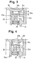
- the valve spool 32 includes variable restriction portions A and B (shown in Fig. 3), which variably restrict the flow of oil through their respective restrictive portions, the degree of restriction determined by the position of the valve spool 32 within the cylinder 31a.
- the control port 31b is constantly connected to the discharge port 21e, the sub-port 31c is constantly connected to the sub-suction port 21d and the main port 31d is constantly connected to the main suction port 21c of the oil pump 20. Since chamber 31a in which the spring 33 is installed is constantly connected to the oil pan 40, no oil pressure is generated which would force the valve spool 32 in the upward direction.
- valve spool 32 when the oil pressure applied to the control port 31b from the oil pump 20 ascends to a first predetermined value, the valve spool 32 is moved in the downward direction against the biasing force of the spring 33 so as to locate at a position (shown in Fig.4) at which the valve spool 32 still disconnects the control port 31b from the sub-port 31c (first condition).
- valve spool 32 When the oil pressure applied to the control port 31b from the oil pump 20 ascends to a second predetermined value (which is larger than the first predetermined value), the valve spool 32 is moved against the biasing force of the spring 33 so as to locate at a position (shown in Fig.5) at which the valve spool 32 still disconnects the sub-port 31c from the main port 31d (second condition).
- valve spool 32 When the oil pressure applied to the control port 31b from the oil pump 20 ascends to a third predetermined value (which is larger than the second predetermined value), the valve spool 32 is moved against the biasing force of the spring 33 so as to locate at a position (shown in Fig.6) at which the valve spool 32 connects the control port 31b and the sub-port 31c, but still disconnects both of said ports from the main port 31d (third condition).
- FIG. 7 A characteristic diagram of this embodiment of the present invention showing the quantity of the operational oil discharged from the oil pump 20 is shown in Fig. 7.
- the first condition of the control valve 30 corresponds to point "a" or "A”
- the second condition of the control valve 30 corresponds to point "b" or "B”
- the third condition of the control valve 30 corresponds to the condition shown as point "c”.
- Fig.7 also illustrates, by a bold dash-single dot-dash line, the amount of oil discharged from a conventional oil pump apparatus (such oil pump apparatus includes an oil pump and a control valve which diverts a potion of the oil pumped out from the oil pump back to a suction port of the oil pump, an oil pan, an oil reservoir , an oil tank and so on in order to reduce the load applied to the oil pump at the medium and high rotation speed ranges of the oil pump 20.).
- a conventional oil pump apparatus includes an oil pump and a control valve which diverts a potion of the oil pumped out from the oil pump back to a suction port of the oil pump, an oil pan, an oil reservoir , an oil tank and so on in order to reduce the load applied to the oil pump at the medium and high rotation speed ranges of the oil pump 20.
- valve spool 32 of the control valve 30 is not moved in the downward direction from the position shown in Fig. 4 at a low crank shaft 10 rotation speed between 0 and N1, as shown on figure 7 (e.g. 1500 rpm)
- the actuator 51 when the actuator 51 is not operated, the sub-port 31c is disconnected from the control port 31b but is connected to the main port 31d. Therefore, a large amount of operation oil is sucked by the oil pump 20 through both the main suction port 21c and the sub suction port 21d of the oil pump 20.
- This is represented in Fig. 7 as a bold line "0 ⁇ a", which shows the quantity of the operational oil discharged from the oil pump 20 at such low rotation speeds.
- the operational oil is discharged from the oil pump 20 to the components 51, 52 and 53 through the discharge conduit 41.
- valve spool 32 of the control valve 30 When the valve spool 32 of the control valve 30 is moved between the first and second positions which are shown in Figs. 4 and 5, respectively, and is not moved further in the downward direction from the position shown in Fig. 5 at a crank shaft 10 rotation speed of between N1 and N2 (e.g. 3000 rpm) when the actuator 51 is not operated, the size of the passages A and B formed between the valve spool 32 and the valve housing 31 which connect the sub-port 31c to the control port 31b and to the main port 31d, respectively, are controlled by the crank shaft 10 rotation speed.
- N1 and N2 e.g. 3000 rpm
- valve spool 32 of the control valve 30 When the valve spool 32 of the control valve 30 is moved between the positions of the second and third conditions, which are shown in Figs. 5 and 6, respectively, and is not moved in the downward direction from the position shown in Fig. 6 at a crank shaft 10 rotation speed between N2 and N3 (e.g. 5000 rpm) when the actuator 51 is not operated, the sub-port 31c is disconnected from the main port 31d and the size of passage formed between the valve spool 32 and the valve housing 31 which connects the sub-port 31c to the control port 31b is controlled such that the size of said passage is in proportion to the crank shaft 10 rotation speed.
- N2 and N3 e.g. 5000 rpm
- valve spool 32 of the control valve 30 When the valve spool 32 of the control valve 30 is moved in the downward direction from the position shown in Fig. 6 at a crank shaft 10 rotation speed higher than N3, at such higher speed the control port 31b is fully connected to the sub-port 31c and the size of passage B formed with the valve spool 32 and the valve housing 31 which connect the main port 31d to the control port 31b and the sub-port 31c is controlled such that the size of said passage is in proportion to the crank shaft 10 rotation speed.
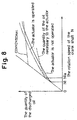
- the oil pump apparatus may comprise an oil pump including the suction ports 21c, 21d constantly connected to each other (a conventional trochoid pump) and a relief valve disposed at the discharge portion of the oil pump, which can be represented by the characteristic diagram shown in Fig. 8, instead of the control valve 30.
- the relief valve starts to relieve the oil pressure at the crank shaft 10 rotation speed N1 when the actuator is not operated and the relief valve starts to relief the oil pressure at the crank shaft 10 rotation speed N1a when the actuator is operated. Therefore, a quantity of the operational oil smaller than that consumed by the actuator (see a characteristic diagram illustrated by a broken line in Fig. 8) is discharged from the oil pump to the components when the actuator is not operated and the quantity of the operational oil exceeding that consumed by the actuator is discharged from the oil pump to the components when the actuator is operated.
- the oil pump 20 may include a plurality (more than two) suction ports.
- the number of the ports and the number of valve portions of the control valve each have to be increased so as to correspond to the number of the suction ports of the oil pump 20.
- the oil pump apparatus can be applied to any industrial or farming equipment, and is not restricted to use only with motor vehicle engines. Further, the type of the oil pump and the driving mechanism of the oil pump can be adequately altered to correspond to a wide variety of uses.
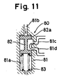
- a rand portion 82a is disposed at an upper end of the valve spool 82 so as to receive the oil pressure which is forced from the control port 81b to the main port 81d at a third control mode (described later).
- the valve spool 82 has a slope 82b (tapered surface) which is sloped from an outer circumferential portion of the rand portion 82a towards the axis of the valve spool 82.
- the slope 82b is disposed at a lower portion of the rand portion 82a as shown in Fig. 9.
- the valve spool 82 has a stepped portion 82c disposed between the outer circumferential portion of the rand portion 82a and the upper end portion of the slope 82b.
- the control valve 80 has a first control mode (see Fig. 11) at which the sub-port 81c, as determined by the amount of oil pressure applied to the control port 81b, is only connected to the main port 81d.
- the sub-port 81c In the second control mode of the control valve 80 (see Fig. 12) the sub-port 81c is also connected to the main port 81d through the variable restriction portion B This second control mode provides for the flow of the operational oil into the sub-port 81c from both the main port 81d and the control port 81b.
- the third control mode of the control valve 80 see Fig.
- the sub-port 81c is connected to the control port 81b and is also connected to the main port 81d through the variable restriction portion B so as to provide for the flow of the operational oil from the control port 81b into both the sub-port 81c and the main port 81d.
- the sub-port 81c is only connected to the control port 81b.
- the sub-port 81c is connected to the control port 81b and the main port 81d so as to provide for the flow of the operational oil from the control port 81b into both the sub-port 81c and the main port 81d.
- the operation of the control valve 80 of the second embodiment of the present invention may be represented by a characteristic diagram of the quantity of the operational oil discharged from the oil pump 20, as shown in Fig. 10.
- the first control mode is illustrated as "0 ⁇ a”
- the second control mode is illustrated as "a ⁇ b”
- the third control mode is illustrated as "b ⁇ c”
- the fourth control mode is illustrated as "c ⁇ d”
- the fifth control mode is shown as a bold line on the right side of"d.
- valve spool 82 of the control valve 80 since the valve spool 82 of the control valve 80 is located at a position schematically shown in Fig. 11 at a rotation speed range of the crank shaft 10 between 0 and N1, the sub-port 81c is disconnected from the control port 81b and is connected to the main port 81d. Therefore, a relatively large amount of operational oil is sucked by the oil pump 20 through both the main suction port 21c and the sub-suction port 21d of the oil pump 20. This is shown as a line "0 ⁇ a" in Fig. 10, which shows the amount of operational oil discharged by the oil pump 20. The operational oil is discharged from the oil pump 20 to the components 51, 52 and 53 through the discharge conduit 41.
- valve spool 82 of the control valve 80 Since the valve spool 82 of the control valve 80 is located at a position schematically shown in Fig. 12 at a crank shaft 10 rotation speed between N1 and N2, the sub-port 81c is connected to the main port 81d (whereby a relatively small quantity of the operational oil flows into the sub-port 81c from the main port 81d due to the flow restriction imposed by the variable restriction portion B) and the quantity of the operational oil which flows into the sub-port 81c from the control port 81b is controlled by the variable restriction portion A in inverse proportion to the crank shaft 10 rotation speed (restriction portion A is pushed open in proportion to the amount of oil pressure).
- the valve spool 82 When the valve spool 82 is in this position, the operational oil flows into the sub-port 81c from the main port 81d and the control port 81b.
- valve spool 82 of the control valve 80 Since the valve spool 82 of the control valve 80 is located at a position schematically shown in Fig. 13 at a crank shaft 10 rotation speed between N2 and N3, the sub-port 81c is connected to the control port 81b (whereby a relatively small quantity of the operational oil flows into the sub-port 81c from the control port 81b due to the restriction imposed by the restriction portion A), and the quantity of the operational oil flowing into the main port 81d from the control port 81b is controlled by the restriction portion B due to the amount of restriction imposed by restriction proportion B which varies in proportion to the crank shaft 10 rotation speed. Thus, the operational oil flows into the sub-port 81c and the main port 81d from the control port 81b.
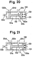
- valve spool 82 of the control valve 80 when the valve spool 82 of the control valve 80 is located at a position schematically shown in Fig. 14, which occurs at a crank shaft 10 rotation speed between N3 and N4, the sub-port 81c is connected to the control port 81b and disconnected from the main port 81d.
- the valve spool 82 When the valve spool 82 is in this position, the operational oil flows into the sub-port 81c from the control port 81b, but said oil cannot flow into the main port 81d from the control port 81b.
- valve spool 82 of the control valve 80 When the valve spool 82 of the control valve 80 is located at a position schematically shown in Fig. 15, which occurs at a crank shaft 10 rotation speed higher than N4, the control port 81b is fully connected to the sub-port 81c and the quantity of the operational oil flowed into the main port 81d from the control port 81b is controlled by the variable restriction portion A, such that the amount of restriction imposed by restriction portion B is in inverse proportion to the crank shaft 10 rotation speed. In this position, the operational oil flows into both the sub-port 81c and the main port 81d from the control port 81b.
- the oil pressure generated at a lower portion of the slope 82b (shown in Fig. 9) is smaller than that generated at the variable restriction portion B, the amount of force applied to the valve spool 82 by the oil pressure in the same direction as the force applied by the spring 83 to the valve spool 82 is reduced. Therefore, the increasing characteristic of the quantity of the operational oil discharged by the oil pump 20 at the third control mode is close to the decreasing characteristic (the hysterisis is small), so that the efficiency of the oil pump apparatus is relatively stable.
- a size L of the rand portion 82a (shown in Fig. 9) in the axial direction of the valve spool 82 can be prevented from being varied by any manufacturing variation of the slope 82b, in order to maintain stable efficiency of the oil pump apparatus.
- a size D of the stepped portion 82c should be preferably small in order to reduce the hysteresis with respect to the quantity of the operational oil discharged by the oil pump 20.
- the control valve 130 includes a valve housing having a cylinder 131a, a first control port 131b, a sub-port 131c, a main port 131d and a second control port 131e.
- the control valve 130 includes a valve spool 132 slidably disposed in the cylinder 131a and to which an oil pressure generated by the oil pump 20 is applied through the second control port 131e (shown in Fig. 17) so as to control a connection between the ports 131b, 131c, 131d and 131e.
- the control valve 130 further includes a spring 133 biasing the valve spool 132 in the left direction, as shown in Fig. 17.
- the valve spool 132 includes variable restriction portions A and B between the valve spool 132 and the valve housing 131.
- control ports 131b, 131e are constantly connected to the discharge port 21e, the sub-port 131c is constantly connected to the sub-suction port 21d, and the main port 131d is constantly connected to the main suction port 21c of the oil pump 20.
- the control valve 130 has a first control mode (see Fig. 17) at which the sub-port 131c is only connected to the main port 131d.
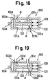
- the second control mode see Fig. 18
- the sub-port 131c is connected to the main port 131d through a semi-restricted position of the variable restriction portion B, and the sub-port 131c is also connected to the first control port 131b through a relatively highly restricted position of the variable restriction portion A, so that the operational oil flows into the sub-port 131c from both the main port 131d and the first control port 131b.
- the third control mode see Fig.
- the sub-port 131c is connected to the first control port 131b and the sub-port 131c is connected to the main port 131d through the variable restriction portion B so that the operational oil flows from the first control port 131b into both the sub-port 131c and the main port 131d.
- the sub-port 131c is only connected to the first control port 131b.
- the sub-port 131c is connected to the first control port 131b, and the second control port 131e is connected to the main port 131d.
- the operational oil from the first control port 131b into the sub-port 131c, and the operational oil also flows from the second control port 131e into the main port 131d.
- FIG. 10 A characteristic diagram showing the quantity of the operational oil discharged from the oil pump 20 with respect to this third embodiment of the present invention is shown in Fig. 10. Because the operation of the control valve 130 is substantially equivalent to that of the control valve 80, further description of said operation is omitted herein.
Landscapes
- Engineering & Computer Science (AREA)
- Physics & Mathematics (AREA)
- Fluid Mechanics (AREA)
- Mechanical Engineering (AREA)
- General Engineering & Computer Science (AREA)
- Details And Applications Of Rotary Liquid Pumps (AREA)
- Details Of Reciprocating Pumps (AREA)
Abstract
Description
Claims (7)
- An oil pump apparatus comprising:an oil pump (20) which is driven by a driving source (10) and connected to a plurality of components (51,52,53) to which an oil is supplied from the oil pump (20) wherein at least one of the components (51,52,53) is an actuator (51) operated by oil pressure generated from the oil pump (20);
CHARACTERIZED BY a control valve (30) preventing excessive oil flow to the components (51,52,53) such that when the actuator (51) is not in operation the quantity of oil supplied to the components (51,52,53) is less than that consumed by the actuator (51) when operating, and when the actuator (51) is in operation the quantity of oil supplied to the components (51,52,53) is greater than that consumed by the actuator (51). - An oil pump apparatus according to claim 1, wherein the oil pump (20) includes a suction opening (21a), a main suction port (21c) constantly connected to the suction opening (21a), a sub-suction port (21d) selectively connected to or disconnected from the suction opening (21a), a discharge opening (21b) and a discharge port (21e) constantly connected to the discharge opening (21b),the control valve (30) includes at least one control port (31b) into which the discharged oil flows from the oil pump (20), a main port (31d) constantly connected to the main suction port (21c), a sub-port (31c) constantly connected to the sub-suction port (21d) , a valve housing (31) having a cylinder (31a) connected to the main port (31d) and the sub-port (31c), a valve spool (32) slidably disposed in the cylinder (31a) and a spring (33) biasing the valve spool (32) in the axial direction of the valve spool (32), andthe valve spool (32) receives the oil pressure from the oil pump (20) at least at one end thereof so as to counteract the bias of the spring (33).
- An oil pump apparatus according to claim 2, wherein the valve spool (32) has a rand portion (82a) and variable restriction portions (A,B) are formed between the valve housing (31) and the rand portion (82a) so as to vary the restriction of the oil flow between the control port (31b), the main port (31d) and the sub-port (31c).
- An oil pump apparatus according to claim 3, wherein the valve spool (32) has a slope (82b) disposed on the rand portion (82a) at the end of the rand portion (82a) facing away from the end that receives oil pressure from the oil pump (20) and the slope (82b) is inclined towards the axis of the valve spool (32) from an outer circumference of the rand portion (82a).
- An oil pump apparatus according to claim 4, wherein the valve spool (32) has a stepped portion (82c) between the outer circumference of the rand portion (82a) and the slope (82b).
- An oil pump apparatus according to any of claims 2 to 5, wherein the control valve (30) has a first control mode at which the sub-port (31c) is only connected to the main port (31d), a second control mode at which the sub-port (31c) is connected to the main port (31d) and the sub-port (31c) is connected to the control port (31b) through the variable restriction portion (A) so that oil flows into the sub-port (31c) from the main port (31d) and the control port (31b), a third control mode at which the sub-port (31c) is connected to the control port (31b) and the sub-port (31c) is connected to the main port (31d) through the variable restriction portion (B) so that oil flows into the main port (31d) and the sub-port (31c) from the control port (31b) and a fourth control mode at which the sub-port (31c) is only connected to the control port (31b).
- An oil pump apparatus according to claim 6, wherein the control valve (30) includes a first control port (131c) which supplies oil pressure to the end of the valve spool (32), and a second control port (131b) for connection to the main port (31d) and or the sub-port (31c) in the second, third and fourth control modes.
Applications Claiming Priority (6)
| Application Number | Priority Date | Filing Date | Title |
|---|---|---|---|
| JP11148997 | 1997-04-28 | ||
| JP11148997A JP3603536B2 (en) | 1997-04-28 | 1997-04-28 | Oil pump device |
| JP111489/97 | 1997-04-28 | ||
| JP13145797 | 1997-05-21 | ||
| JP13145797A JP3319337B2 (en) | 1997-05-21 | 1997-05-21 | Oil pump device |
| JP131457/97 | 1997-05-21 |
Publications (3)
| Publication Number | Publication Date |
|---|---|
| EP0875678A2 true EP0875678A2 (en) | 1998-11-04 |
| EP0875678A3 EP0875678A3 (en) | 2000-01-26 |
| EP0875678B1 EP0875678B1 (en) | 2004-09-22 |
Family
ID=26450873
Family Applications (1)
| Application Number | Title | Priority Date | Filing Date |
|---|---|---|---|
| EP98201366A Expired - Lifetime EP0875678B1 (en) | 1997-04-28 | 1998-04-28 | Oil pump control valve |
Country Status (3)
| Country | Link |
|---|---|
| US (2) | US6004111A (en) |
| EP (1) | EP0875678B1 (en) |
| DE (1) | DE69826358T2 (en) |
Cited By (2)
| Publication number | Priority date | Publication date | Assignee | Title |
|---|---|---|---|---|
| GB2441773A (en) * | 2006-09-15 | 2008-03-19 | Concentric Vfp Ltd | Pump Control System |
| EP1921317A3 (en) * | 2006-11-07 | 2010-04-28 | Aisin Seiki Kabushiki Kaisha | Oil supplying apparatus for engine |
Families Citing this family (10)
| Publication number | Priority date | Publication date | Assignee | Title |
|---|---|---|---|---|
| US6004111A (en) * | 1997-04-28 | 1999-12-21 | Aisin Seiki Kabushiki Kaisha | Oil pump apparatus |
| JP2001355579A (en) * | 2000-06-12 | 2001-12-26 | Sanshin Ind Co Ltd | Oil pump structure for engine |
| DE112007000188A5 (en) * | 2006-02-02 | 2009-01-15 | Avl List Gmbh | Crankcase ventilation system |
| US8297943B2 (en) * | 2006-11-06 | 2012-10-30 | Magna Powertrain, Inc. | Pump control using overpressure source |
| DE102010022137A1 (en) * | 2010-05-20 | 2011-11-24 | Gm Global Technology Operations Llc (N.D.Ges.D. Staates Delaware) | Pump for a lubrication system of an internal combustion engine |
| US8801396B2 (en) * | 2010-06-04 | 2014-08-12 | Chrysler Group Llc | Oil pump system for an engine |
| JP5278775B2 (en) | 2010-12-06 | 2013-09-04 | アイシン精機株式会社 | Oil supply device |
| JP5374550B2 (en) | 2011-07-12 | 2013-12-25 | 本田技研工業株式会社 | Oil pump relief device |
| KR101326850B1 (en) * | 2012-10-04 | 2013-11-11 | 기아자동차주식회사 | System and method for controlling an oil pump |
| JP5993291B2 (en) * | 2012-11-27 | 2016-09-14 | 日立オートモティブシステムズ株式会社 | Variable displacement pump |
Citations (1)
| Publication number | Priority date | Publication date | Assignee | Title |
|---|---|---|---|---|
| JPS6123485A (en) | 1984-07-11 | 1986-01-31 | Matsushita Electric Ind Co Ltd | Time axis correction device |
Family Cites Families (14)
| Publication number | Priority date | Publication date | Assignee | Title |
|---|---|---|---|---|
| US3314495A (en) * | 1964-12-07 | 1967-04-18 | Trw Inc | Valving system for power steering pump |
| US3426785A (en) * | 1966-12-01 | 1969-02-11 | Chrysler Corp | Power steering flow control device |
| US4244389A (en) * | 1978-09-08 | 1981-01-13 | Jidoshakiki Co., Ltd. | Flow control valve |
| JPS57173513A (en) * | 1981-04-17 | 1982-10-25 | Nippon Soken Inc | Variable valve engine |
| JPS57193791A (en) * | 1981-05-25 | 1982-11-29 | Jidosha Kiki Co Ltd | Oil pump |
| JPS5862394A (en) * | 1981-10-08 | 1983-04-13 | Jidosha Kiki Co Ltd | Oil pump |
| GB2144520B (en) * | 1983-08-06 | 1986-04-09 | Cessna Aircraft Co | Flow limiting valve |
| CA1328589C (en) * | 1985-08-21 | 1994-04-19 | Honda Giken Kogyo Kabushiki Kaisha (Also Trading As Honda Motor Co., Ltd .) | Oil supply system for a valve operating mechanism in internal combustion engines |
| JPH0694819B2 (en) * | 1987-01-13 | 1994-11-24 | マツダ株式会社 | Engine hydraulic control device |
| DE3837599A1 (en) * | 1988-11-05 | 1990-05-10 | Daimler Benz Ag | Gear pump having two pairs of gear wheels arranged next to one another in the pump casing |
| JPH0742445A (en) * | 1993-08-02 | 1995-02-10 | Tsuuden:Kk | Safety and starting device of automatic door |
| JP3531769B2 (en) * | 1994-08-25 | 2004-05-31 | アイシン精機株式会社 | Oil pump device |
| CA2159672C (en) * | 1994-10-17 | 2009-09-15 | Siegfried A. Eisenmann | A valve train with suction-controlled ring gear/internal gear pump |
| US6004111A (en) * | 1997-04-28 | 1999-12-21 | Aisin Seiki Kabushiki Kaisha | Oil pump apparatus |
-
1998
- 1998-04-27 US US09/066,565 patent/US6004111A/en not_active Expired - Lifetime
- 1998-04-28 DE DE69826358T patent/DE69826358T2/en not_active Expired - Fee Related
- 1998-04-28 EP EP98201366A patent/EP0875678B1/en not_active Expired - Lifetime
-
1999
- 1999-11-08 US US09/435,777 patent/US6247904B1/en not_active Expired - Fee Related
Patent Citations (1)
| Publication number | Priority date | Publication date | Assignee | Title |
|---|---|---|---|---|
| JPS6123485A (en) | 1984-07-11 | 1986-01-31 | Matsushita Electric Ind Co Ltd | Time axis correction device |
Cited By (6)
| Publication number | Priority date | Publication date | Assignee | Title |
|---|---|---|---|---|
| GB2441773A (en) * | 2006-09-15 | 2008-03-19 | Concentric Vfp Ltd | Pump Control System |
| GB2441773B (en) * | 2006-09-15 | 2011-02-23 | Concentric Vfp Ltd | Engine Lubricant Pump Control System |
| EP1921317A3 (en) * | 2006-11-07 | 2010-04-28 | Aisin Seiki Kabushiki Kaisha | Oil supplying apparatus for engine |
| US7810467B2 (en) | 2006-11-07 | 2010-10-12 | Aisin Seiki Kabushiki Kaisha | Oil supplying apparatus for engine |
| EP2275682A1 (en) * | 2006-11-07 | 2011-01-19 | Aisin Seiki Kabushiki Kaisha | Oil supplying apparatus for engine |
| CN101178064B (en) * | 2006-11-07 | 2012-07-04 | 爱信精机株式会社 | Oil supplying apparatus for engine |
Also Published As
| Publication number | Publication date |
|---|---|
| EP0875678A3 (en) | 2000-01-26 |
| DE69826358D1 (en) | 2004-10-28 |
| US6004111A (en) | 1999-12-21 |
| EP0875678B1 (en) | 2004-09-22 |
| US6247904B1 (en) | 2001-06-19 |
| DE69826358T2 (en) | 2005-02-17 |
Similar Documents
| Publication | Publication Date | Title |
|---|---|---|
| JP3531769B2 (en) | Oil pump device | |
| US7011069B2 (en) | Oil supply system for engine | |
| JP4446622B2 (en) | Oil pump for internal combustion engine and method of using the same | |
| US6004111A (en) | Oil pump apparatus | |
| US20060171818A1 (en) | Oil pump | |
| JP3424409B2 (en) | Oil pump device | |
| JP2003328959A (en) | Oil pump | |
| JPH10266978A (en) | Vane pump | |
| JP3371709B2 (en) | Oil pump device | |
| JP4875236B2 (en) | Oil pump device | |
| JPH06221274A (en) | Oil pump for automatic transmission | |
| JP3319337B2 (en) | Oil pump device | |
| JPH08121567A (en) | Oil pump structure | |
| JP3603536B2 (en) | Oil pump device | |
| JP3546740B2 (en) | Oil pump device | |
| EP1503051B1 (en) | Oil pump | |
| JP3608688B2 (en) | Oil pump device | |
| JP2003193819A (en) | Oil pump device for internal combustion engine | |
| JP4439148B2 (en) | Engine lubrication equipment | |
| EP1201953A2 (en) | Fluid clutch | |
| JP2836427B2 (en) | Variable valve timing device | |
| JP3230355B2 (en) | Oil supply device for internal combustion engine | |
| JP2970627B2 (en) | Oil pump device | |
| JPH1137059A (en) | Lubrication device in hydraulic pump or hydraulic motor | |
| JP4066512B2 (en) | Engine oil pump structure |
Legal Events
| Date | Code | Title | Description |
|---|---|---|---|
| PUAI | Public reference made under article 153(3) epc to a published international application that has entered the european phase |
Free format text: ORIGINAL CODE: 0009012 |
|
| AK | Designated contracting states |
Kind code of ref document: A2 Designated state(s): DE FR GB |
|
| AX | Request for extension of the european patent |
Free format text: AL;LT;LV;MK;RO;SI |
|
| PUAL | Search report despatched |
Free format text: ORIGINAL CODE: 0009013 |
|
| RIC1 | Information provided on ipc code assigned before grant |
Free format text: 7F 15B 11/05 A, 7F 04C 15/04 B |
|
| AK | Designated contracting states |
Kind code of ref document: A3 Designated state(s): AT BE CH CY DE DK ES FI FR GB GR IE IT LI LU MC NL PT SE |
|
| AX | Request for extension of the european patent |
Free format text: AL;LT;LV;MK;RO;SI |
|
| 17P | Request for examination filed |
Effective date: 20000221 |
|
| AKX | Designation fees paid |
Free format text: DE FR GB |
|
| 17Q | First examination report despatched |
Effective date: 20030417 |
|
| GRAP | Despatch of communication of intention to grant a patent |
Free format text: ORIGINAL CODE: EPIDOSNIGR1 |
|
| GRAS | Grant fee paid |
Free format text: ORIGINAL CODE: EPIDOSNIGR3 |
|
| GRAA | (expected) grant |
Free format text: ORIGINAL CODE: 0009210 |
|
| AK | Designated contracting states |
Kind code of ref document: B1 Designated state(s): DE FR GB |
|
| REG | Reference to a national code |
Ref country code: GB Ref legal event code: FG4D |
|
| REF | Corresponds to: |
Ref document number: 69826358 Country of ref document: DE Date of ref document: 20041028 Kind code of ref document: P |
|
| ET | Fr: translation filed | ||
| PLBE | No opposition filed within time limit |
Free format text: ORIGINAL CODE: 0009261 |
|
| STAA | Information on the status of an ep patent application or granted ep patent |
Free format text: STATUS: NO OPPOSITION FILED WITHIN TIME LIMIT |
|
| 26N | No opposition filed |
Effective date: 20050623 |
|
| REG | Reference to a national code |
Ref country code: GB Ref legal event code: 746 Effective date: 20080506 |
|
| PGFP | Annual fee paid to national office [announced via postgrant information from national office to epo] |
Ref country code: FR Payment date: 20080312 Year of fee payment: 11 Ref country code: DE Payment date: 20080502 Year of fee payment: 11 |
|
| PGFP | Annual fee paid to national office [announced via postgrant information from national office to epo] |
Ref country code: GB Payment date: 20080430 Year of fee payment: 11 |
|
| GBPC | Gb: european patent ceased through non-payment of renewal fee |
Effective date: 20090428 |
|
| REG | Reference to a national code |
Ref country code: FR Ref legal event code: ST Effective date: 20091231 |
|
| PG25 | Lapsed in a contracting state [announced via postgrant information from national office to epo] |
Ref country code: DE Free format text: LAPSE BECAUSE OF NON-PAYMENT OF DUE FEES Effective date: 20091103 |
|
| PG25 | Lapsed in a contracting state [announced via postgrant information from national office to epo] |
Ref country code: GB Free format text: LAPSE BECAUSE OF NON-PAYMENT OF DUE FEES Effective date: 20090428 Ref country code: FR Free format text: LAPSE BECAUSE OF NON-PAYMENT OF DUE FEES Effective date: 20091222 |