EP0875321A1 - Rotierendes werkzeug für Werkzeugmaschine und Werkzeugsmaschine die dieses Werkzeug verwendet - Google Patents
Rotierendes werkzeug für Werkzeugmaschine und Werkzeugsmaschine die dieses Werkzeug verwendet Download PDFInfo
- Publication number
- EP0875321A1 EP0875321A1 EP97830200A EP97830200A EP0875321A1 EP 0875321 A1 EP0875321 A1 EP 0875321A1 EP 97830200 A EP97830200 A EP 97830200A EP 97830200 A EP97830200 A EP 97830200A EP 0875321 A1 EP0875321 A1 EP 0875321A1
- Authority
- EP
- European Patent Office
- Prior art keywords
- tool
- spindle
- frustoconical surface
- machine
- tool according
- Prior art date
- Legal status (The legal status is an assumption and is not a legal conclusion. Google has not performed a legal analysis and makes no representation as to the accuracy of the status listed.)
- Granted
Links
Images


Classifications
-
- B—PERFORMING OPERATIONS; TRANSPORTING
- B23—MACHINE TOOLS; METAL-WORKING NOT OTHERWISE PROVIDED FOR
- B23B—TURNING; BORING
- B23B31/00—Chucks; Expansion mandrels; Adaptations thereof for remote control
- B23B31/02—Chucks
- B23B31/10—Chucks characterised by the retaining or gripping devices or their immediate operating means
- B23B31/11—Retention by threaded connection
- B23B31/1107—Retention by threaded connection for conical parts
- B23B31/1122—Retention by threaded connection for conical parts using cylindrical threads
-
- B—PERFORMING OPERATIONS; TRANSPORTING
- B23—MACHINE TOOLS; METAL-WORKING NOT OTHERWISE PROVIDED FOR
- B23C—MILLING
- B23C5/00—Milling-cutters
- B23C5/02—Milling-cutters characterised by the shape of the cutter
- B23C5/04—Plain cutters, i.e. having essentially a cylindrical or tapered cutting surface of substantial length
Definitions
- the present invention relates to a rotating tool for machine tools, of the type comprising a frustoconical surface for coupling the tool on the rotating spindle of the machine tool by means of a so-called conical interface.
- the invention also relates to a machine tool with a rotating spindle and more specifically - but not exclusively - to copy milling machines for machining pieces made of wood, such as elongate parts for furniture, chairs and the like.
- tools equipped with a frustoconical tang for fixing to the spindle are made with a tang which extends axially beyond the active surface of the tool. These are typically used in machine tools for machining metals.
- Fig. 1 shows the conventional arrangement of two spindles of a machine of this type which machine, by means of two tools, two opposite faces of a piece P.
- the spindle shafts are indicated by M, and M1 indicates their front portions onto which the two tools U are slipped and locked by the ring nuts G.
- B indicates a means of locking the piece P on the working surface L.
- the system for mounting the tools illustrated in Fig. 1 is particularly inconvenient because these tools have a great height (typically of the order of 15-20 cm) and the operating units have no movement along the axis of the spindle.
- a first aim of the present invention is the production of a tool with a conical interface which makes it possible to overcome the limitations of use of the conventional tools of this type.
- Another aim of the present invention is the production of a tool with a conical interface which makes it possible to reduce the stresses on the spindles and the size of the respective supports.
- a further aim of the present invention is the production of a tool with a conical interface which can be used in machine tools which have parallel, opposite pairs of spindles which have to machine in close proximity.
- Yet another aim of the present invention is the production of a tool with a conical interface, which is particularly suitable for use in copy milling machines.
- the aim of the invention is the production of a machine tool with a pair of spindles with parallel axes and with a conical interface for the attachment of the tools.
- the frustoconical surface defines in the recessed seat a frustoconical tang similar to that of conventional tools but so as to reduce the distance of the tool in relation to the supports of the spindle and to avoid increasing the radial dimension of these.
- the frustoconical surface is formed at one end of a small shaft which is inserted in an axial hole of the tool and can be locked to the tool in an appropriate manner, for example by means of a ring nut or other equivalent means preferably arranged at the opposite end of the small shaft.
- Fig. 1 illustrates the conventional system of mounting the tools in a copy milling machine, the general structure of which is shown in Fig. 2.
- Machines of this type are known per se and will be described only to the extent necessary for understanding the invention.
- the machine has a base 1 with a working surface L which is movable in the directions fL and on which a template D and a piece P are fixed by locking means B.
- Reference numbers 9, 10, 11 and 12 indicate operating units with tools generally indicated by U. A corresponding arrangement of operating units is provided on the opposite side.
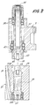
- the tool is generally indicated by 21 and has an axial through-hole, in which a small shaft 23 is inserted and locked.
- two recessed seats 25A, 25B are made in the axial extent A of the tool.
- a locking ring nut 27 screwed onto the lower end of the small shaft 23 is accommodated in the seat 25A.
- the small shaft 23 has a frustoconical surface 29 defining a frustoconical tang accommodated inside the seat 25B.
- a collar 31 is provided, which forms a stop on the mouth of the axial hole for locking the small shaft.
- the frustoconical tang formed by the surface 29 has a threaded axial hole 33 inside which a stay bolt 35 coaxial with the spindle engages, which can be actuated at the rear for gripping the tool on the spindle 35.
- the latter is supported by bearings 39, 41 and has a projecting front portion 43 which, in the mounted position (Fig. 4), is inserted in the recessed seat 25B.
- the spindle portion 43 has on the inside a frustoconical cavity 45 which constitutes the female part of the conical interface, the male part of which is constituted by the surface 29.
Landscapes
- Engineering & Computer Science (AREA)
- Mechanical Engineering (AREA)
- Automatic Tool Replacement In Machine Tools (AREA)
- Cutting Tools, Boring Holders, And Turrets (AREA)
Priority Applications (3)
| Application Number | Priority Date | Filing Date | Title |
|---|---|---|---|
| ES97830200T ES2143841T3 (es) | 1997-04-30 | 1997-04-30 | Herramienta rotatoria para una maquina-herramienta y maquina-herramienta que utiliza dicha herramienta. |
| EP19970830200 EP0875321B1 (de) | 1997-04-30 | 1997-04-30 | Rotierendes Werkzeug für Werkzeugmaschine und Werkzeugsmaschine die dieses Werkzeug verwendet |
| DE1997601320 DE69701320T2 (de) | 1997-04-30 | 1997-04-30 | Rotierendes Werkzeug für Werkzeugmaschine und Werkzeugsmaschine die dieses Werkzeug verwendet |
Applications Claiming Priority (1)
| Application Number | Priority Date | Filing Date | Title |
|---|---|---|---|
| EP19970830200 EP0875321B1 (de) | 1997-04-30 | 1997-04-30 | Rotierendes Werkzeug für Werkzeugmaschine und Werkzeugsmaschine die dieses Werkzeug verwendet |
Publications (2)
| Publication Number | Publication Date |
|---|---|
| EP0875321A1 true EP0875321A1 (de) | 1998-11-04 |
| EP0875321B1 EP0875321B1 (de) | 2000-02-23 |
Family
ID=8230623
Family Applications (1)
| Application Number | Title | Priority Date | Filing Date |
|---|---|---|---|
| EP19970830200 Expired - Lifetime EP0875321B1 (de) | 1997-04-30 | 1997-04-30 | Rotierendes Werkzeug für Werkzeugmaschine und Werkzeugsmaschine die dieses Werkzeug verwendet |
Country Status (3)
| Country | Link |
|---|---|
| EP (1) | EP0875321B1 (de) |
| DE (1) | DE69701320T2 (de) |
| ES (1) | ES2143841T3 (de) |
Cited By (2)
| Publication number | Priority date | Publication date | Assignee | Title |
|---|---|---|---|---|
| WO2002076661A1 (de) * | 2001-03-22 | 2002-10-03 | Johne + Co. Präzisionswerkzeuge Gmbh | Werkzeug und werkzeuganordnung |
| JP2014018914A (ja) * | 2012-07-18 | 2014-02-03 | Hitachi Koki Co Ltd | 動力工具及びチャック固定方法 |
Citations (2)
| Publication number | Priority date | Publication date | Assignee | Title |
|---|---|---|---|---|
| EP0123156A2 (de) * | 1983-04-22 | 1984-10-31 | Montanwerke Walter Gmbh | Mehrteiliges Spannsystem, insbesondere für rundlaufende Werkzeuge |
| DE3642132C1 (de) * | 1986-12-10 | 1988-03-24 | Krupp Gmbh | Werkzeugkupplung zur Verbindung eines Werkzeugschaftes und eines Werkzeughalters |
-
1997
- 1997-04-30 EP EP19970830200 patent/EP0875321B1/de not_active Expired - Lifetime
- 1997-04-30 DE DE1997601320 patent/DE69701320T2/de not_active Expired - Fee Related
- 1997-04-30 ES ES97830200T patent/ES2143841T3/es not_active Expired - Lifetime
Patent Citations (2)
| Publication number | Priority date | Publication date | Assignee | Title |
|---|---|---|---|---|
| EP0123156A2 (de) * | 1983-04-22 | 1984-10-31 | Montanwerke Walter Gmbh | Mehrteiliges Spannsystem, insbesondere für rundlaufende Werkzeuge |
| DE3642132C1 (de) * | 1986-12-10 | 1988-03-24 | Krupp Gmbh | Werkzeugkupplung zur Verbindung eines Werkzeugschaftes und eines Werkzeughalters |
Cited By (2)
| Publication number | Priority date | Publication date | Assignee | Title |
|---|---|---|---|---|
| WO2002076661A1 (de) * | 2001-03-22 | 2002-10-03 | Johne + Co. Präzisionswerkzeuge Gmbh | Werkzeug und werkzeuganordnung |
| JP2014018914A (ja) * | 2012-07-18 | 2014-02-03 | Hitachi Koki Co Ltd | 動力工具及びチャック固定方法 |
Also Published As
| Publication number | Publication date |
|---|---|
| EP0875321B1 (de) | 2000-02-23 |
| DE69701320D1 (de) | 2000-03-30 |
| DE69701320T2 (de) | 2000-08-24 |
| ES2143841T3 (es) | 2000-05-16 |
Similar Documents
| Publication | Publication Date | Title |
|---|---|---|
| EP0875321B1 (de) | Rotierendes Werkzeug für Werkzeugmaschine und Werkzeugsmaschine die dieses Werkzeug verwendet | |
| EP1055485A3 (de) | Werkzeugmaschine zum Bearbeiten von länglichen symmetrischen Gegenständen sowie Bauteilen von Stühlen, Möbeln und anderen ähnlichen Gegenständen | |
| CA2245327A1 (en) | Lathe charger | |
| US9089911B2 (en) | Side milling arbor with quad drive key assist | |
| US3174402A (en) | Loose jaw collet | |
| CN209736637U (zh) | 一种滚珠花键加工用车床 | |
| CN209886753U (zh) | 用于铣床的多面加工机构 | |
| CN208976919U (zh) | 大型同步电动机转子轴人字形磁钢安装槽加工用的铣床 | |
| KR0177327B1 (ko) | 공작물의 슬롯 깊이조절용 가공공구 | |
| US4257724A (en) | Milling tool for machining cylindrical sections | |
| CN220717885U (zh) | 一种多轴万向铣头装置 | |
| CN101157254B (zh) | 一种多功能石材加工中心用复合工作头 | |
| KR102371353B1 (ko) | 양방향 가공이 가능한 앵글 헤드 | |
| CN210997453U (zh) | 一种全自动雕刻震动刀一体机 | |
| JP4458590B2 (ja) | ガイドブッシュ | |
| CN215392501U (zh) | 一种数控车床副主轴尾座 | |
| CN219766796U (zh) | 一种万向轴联接器加工用数控车床 | |
| CN2327497Y (zh) | 离心可调式磨孔机 | |
| KR100988612B1 (ko) | 선반용 가공공구 및 이를 이용한 가공방법 | |
| CN209969690U (zh) | 一种用于五面体加工的铣头自动交换结构 | |
| KR100226718B1 (ko) | 공작기계의 스핀들헤드 | |
| SU865537A1 (ru) | Приспособление к токарно-затыловочному станку | |
| JPS6343002Y2 (de) | ||
| Kellock | Grinding defines its terms | |
| JP2004154886A (ja) | 工作機械のアーバ |
Legal Events
| Date | Code | Title | Description |
|---|---|---|---|
| PUAI | Public reference made under article 153(3) epc to a published international application that has entered the european phase |
Free format text: ORIGINAL CODE: 0009012 |
|
| 17P | Request for examination filed |
Effective date: 19971209 |
|
| AK | Designated contracting states |
Kind code of ref document: A1 Designated state(s): BE DE ES FR GB IT NL |
|
| GRAG | Despatch of communication of intention to grant |
Free format text: ORIGINAL CODE: EPIDOS AGRA |
|
| 17Q | First examination report despatched |
Effective date: 19990427 |
|
| AKX | Designation fees paid |
Free format text: BE DE ES FR GB IT NL |
|
| GRAG | Despatch of communication of intention to grant |
Free format text: ORIGINAL CODE: EPIDOS AGRA |
|
| GRAH | Despatch of communication of intention to grant a patent |
Free format text: ORIGINAL CODE: EPIDOS IGRA |
|
| GRAH | Despatch of communication of intention to grant a patent |
Free format text: ORIGINAL CODE: EPIDOS IGRA |
|
| ITF | It: translation for a ep patent filed |
Owner name: UFFICIO TECNICO ING. A. MANNUCCI |
|
| GRAA | (expected) grant |
Free format text: ORIGINAL CODE: 0009210 |
|
| AK | Designated contracting states |
Kind code of ref document: B1 Designated state(s): BE DE ES FR GB IT NL |
|
| PG25 | Lapsed in a contracting state [announced via postgrant information from national office to epo] |
Ref country code: NL Free format text: LAPSE BECAUSE OF FAILURE TO SUBMIT A TRANSLATION OF THE DESCRIPTION OR TO PAY THE FEE WITHIN THE PRESCRIBED TIME-LIMIT Effective date: 20000223 Ref country code: BE Free format text: LAPSE BECAUSE OF FAILURE TO SUBMIT A TRANSLATION OF THE DESCRIPTION OR TO PAY THE FEE WITHIN THE PRESCRIBED TIME-LIMIT Effective date: 20000223 |
|
| REF | Corresponds to: |
Ref document number: 69701320 Country of ref document: DE Date of ref document: 20000330 |
|
| ET | Fr: translation filed | ||
| REG | Reference to a national code |
Ref country code: ES Ref legal event code: FG2A Ref document number: 2143841 Country of ref document: ES Kind code of ref document: T3 |
|
| NLV1 | Nl: lapsed or annulled due to failure to fulfill the requirements of art. 29p and 29m of the patents act | ||
| PLBE | No opposition filed within time limit |
Free format text: ORIGINAL CODE: 0009261 |
|
| STAA | Information on the status of an ep patent application or granted ep patent |
Free format text: STATUS: NO OPPOSITION FILED WITHIN TIME LIMIT |
|
| 26N | No opposition filed | ||
| REG | Reference to a national code |
Ref country code: GB Ref legal event code: IF02 |
|
| PGFP | Annual fee paid to national office [announced via postgrant information from national office to epo] |
Ref country code: FR Payment date: 20030327 Year of fee payment: 7 |
|
| PGFP | Annual fee paid to national office [announced via postgrant information from national office to epo] |
Ref country code: ES Payment date: 20030411 Year of fee payment: 7 |
|
| PGFP | Annual fee paid to national office [announced via postgrant information from national office to epo] |
Ref country code: GB Payment date: 20030430 Year of fee payment: 7 |
|
| PGFP | Annual fee paid to national office [announced via postgrant information from national office to epo] |
Ref country code: DE Payment date: 20030623 Year of fee payment: 7 |
|
| PG25 | Lapsed in a contracting state [announced via postgrant information from national office to epo] |
Ref country code: GB Free format text: LAPSE BECAUSE OF NON-PAYMENT OF DUE FEES Effective date: 20040430 |
|
| PG25 | Lapsed in a contracting state [announced via postgrant information from national office to epo] |
Ref country code: ES Free format text: LAPSE BECAUSE OF NON-PAYMENT OF DUE FEES Effective date: 20040503 |
|
| PG25 | Lapsed in a contracting state [announced via postgrant information from national office to epo] |
Ref country code: DE Free format text: LAPSE BECAUSE OF NON-PAYMENT OF DUE FEES Effective date: 20041103 |
|
| GBPC | Gb: european patent ceased through non-payment of renewal fee |
Effective date: 20040430 |
|
| PG25 | Lapsed in a contracting state [announced via postgrant information from national office to epo] |
Ref country code: FR Free format text: LAPSE BECAUSE OF NON-PAYMENT OF DUE FEES Effective date: 20041231 |
|
| REG | Reference to a national code |
Ref country code: FR Ref legal event code: ST |
|
| PG25 | Lapsed in a contracting state [announced via postgrant information from national office to epo] |
Ref country code: IT Free format text: LAPSE BECAUSE OF NON-PAYMENT OF DUE FEES;WARNING: LAPSES OF ITALIAN PATENTS WITH EFFECTIVE DATE BEFORE 2007 MAY HAVE OCCURRED AT ANY TIME BEFORE 2007. THE CORRECT EFFECTIVE DATE MAY BE DIFFERENT FROM THE ONE RECORDED. Effective date: 20050430 |
|
| REG | Reference to a national code |
Ref country code: ES Ref legal event code: FD2A Effective date: 20040503 |