EP0875194B1 - Appareil portable de nettoyage à la vapeur de surfaces dures ou souples - Google Patents
Appareil portable de nettoyage à la vapeur de surfaces dures ou souples Download PDFInfo
- Publication number
- EP0875194B1 EP0875194B1 EP98401033A EP98401033A EP0875194B1 EP 0875194 B1 EP0875194 B1 EP 0875194B1 EP 98401033 A EP98401033 A EP 98401033A EP 98401033 A EP98401033 A EP 98401033A EP 0875194 B1 EP0875194 B1 EP 0875194B1
- Authority
- EP
- European Patent Office
- Prior art keywords
- steam
- resistor
- additive
- elbow
- shielded resistor
- Prior art date
- Legal status (The legal status is an assumption and is not a legal conclusion. Google has not performed a legal analysis and makes no representation as to the accuracy of the status listed.)
- Expired - Lifetime
Links
Images


Classifications
-
- A—HUMAN NECESSITIES
- A47—FURNITURE; DOMESTIC ARTICLES OR APPLIANCES; COFFEE MILLS; SPICE MILLS; SUCTION CLEANERS IN GENERAL
- A47L—DOMESTIC WASHING OR CLEANING; SUCTION CLEANERS IN GENERAL
- A47L11/00—Machines for cleaning floors, carpets, furniture, walls, or wall coverings
- A47L11/40—Parts or details of machines not provided for in groups A47L11/02 - A47L11/38, or not restricted to one of these groups, e.g. handles, arrangements of switches, skirts, buffers, levers
- A47L11/408—Means for supplying cleaning or surface treating agents
- A47L11/4086—Arrangements for steam generation
-
- A—HUMAN NECESSITIES
- A47—FURNITURE; DOMESTIC ARTICLES OR APPLIANCES; COFFEE MILLS; SPICE MILLS; SUCTION CLEANERS IN GENERAL
- A47L—DOMESTIC WASHING OR CLEANING; SUCTION CLEANERS IN GENERAL
- A47L1/00—Cleaning windows
- A47L1/06—Hand implements
- A47L1/08—Hand implements with provision for supplying liquids, e.g. cleaning agents
-
- A—HUMAN NECESSITIES
- A47—FURNITURE; DOMESTIC ARTICLES OR APPLIANCES; COFFEE MILLS; SPICE MILLS; SUCTION CLEANERS IN GENERAL
- A47L—DOMESTIC WASHING OR CLEANING; SUCTION CLEANERS IN GENERAL
- A47L11/00—Machines for cleaning floors, carpets, furniture, walls, or wall coverings
- A47L11/34—Machines for treating carpets in position by liquid, foam, or vapour, e.g. by steam
-
- F—MECHANICAL ENGINEERING; LIGHTING; HEATING; WEAPONS; BLASTING
- F22—STEAM GENERATION
- F22B—METHODS OF STEAM GENERATION; STEAM BOILERS
- F22B1/00—Methods of steam generation characterised by form of heating method
- F22B1/28—Methods of steam generation characterised by form of heating method in boilers heated electrically
- F22B1/284—Methods of steam generation characterised by form of heating method in boilers heated electrically with water in reservoirs
Definitions
- the present invention relates to a portable device omnidirectional for steam cleaning of hard surfaces as well that flexible, comprising a housing provided with a handle, an orifice water supply, an electrical power cord, a cleaning, a steam generator integrated in the housing and comprising means for storing a water reserve and electrical means for heating of this water reserve to produce water vapor, and means for selectively distributing water vapor to the head of cleaning.
- these portable devices are generally low power, designed to provide a jet of steam through a dispenser, and fitted with a squeegee, so that these devices are not well only suitable for cleaning smooth and hard surfaces, such as windows or tiles.
- Another steam production system is to use a labyrinth.
- the water powered by a pump the suction of a tank flows in a long heated path below the heating point where gradually it turns into vapor.
- Such a system has the disadvantage of scaling easily and quickly, and being relatively bulky, heavy and expensive.
- Capillary-type steam generators have also been proposed which ensure the storage of water in a porous body brought into contact with a electric heater which ensures production instant steam.
- Such a type of steam generator is light, good market and relatively insensitive to scaling, which gives it good autonomy in the context of a portable device.
- the apparatus comprises electrical heating means comprising a switch and a cartridge comprising at least one ceramic resistor, the instant steam generator comprising an enclosure intended to keep the capillary body compressed around said cartridge.
- the present invention aims to remedy the aforementioned drawbacks and to provide a portable steam cleaning device that is suitable for smooth and hard surfaces as well as for flexible surfaces, such as that the covering surfaces of textile material, and in particular delivers significant power with a significant vapor flow while being lightweight, inexpensive, quick to set up, easy to use in all positions, with high operational safety and reduced maintenance.
- a portable device omnidirectional for steam cleaning of hard surfaces as well that flexible, comprising a housing provided with a handle, an orifice water supply, an electrical power cord, a cleaning, a steam generator integrated in the housing and comprising means for storing a water reserve and electrical means for heating of this water reserve to produce water vapor, and means for selectively distributing water vapor to the head of cleaning, characterized in that it includes a steam generator instantaneous with low thermal inertia working at atmospheric pressure and comprising a capillary body for storage in divided form, of the entire water reserve to be evaporated, the capillary body being compressed around electrical heating means which include a resistor armored overmolded in a metallic material good conductor of heat to form a heating body, with which is associated at least one element of thermal transmission which is connected to the hottest part of the body and is fitted with a thermal sensor to optimize the control of the supply of the shielded resistor and its safety regardless of the spatial orientation of the steam generator.
- the armored resistance has the shape of a U with two straight branches and an elbow connecting the two straight branches.
- a transmission element can be provided rectilinear thermal connected to the heating body in the vicinity of the part internal elbow of the U-shaped armored resistor, fitted with a sensor or a thermal transmission element connected to the body of heats in the vicinity of the external part of the armored resistance elbow U-shaped, and equipped with a thermal sensor, or two elements of different thermal transmission connected to the heater respectively in the vicinity of the internal part and the external part of the elbow of the U-shaped armored resistor.
- the first and second thermal sensors associated with the elements of thermal transmission connected in the vicinity of the internal and external parts of the armored resistance elbow have setpoints different.
- the body of heater includes ribs arranged in the vicinity of the elbow of the armored resistor, between the straight branches of this armored resistor.
- the body storage capillary comprises a first layer of fibers oriented in a plane parallel to the plane defined by the armored resistance and perpendicular to the two straight branches of this resistance armored, in a zone close to the elbow of the armored resistance.
- the capillary storage body comprises a second layer of fibers oriented perpendicular to the plane defined by the armored resistance, in areas near the two straight branches and away from the elbow of the armored resistance.
- the first ply of the capillary body of storage located in an area near the elbow of the resistance includes greater compression or volume than the second ply.
- each element of thermal transmission is surrounded by a thermally insulating material, in its portion in contact with the porous capillary body.
- the generator steam includes a first waterproof and removable enclosure in which opens the water supply opening, in which a primary water vapor distribution duct and inside which finds a second enclosure provided with perforations and ensuring compression of the storage capillary body around the heating body.
- the body of heater has a plate located in a mean plane defined by the armored resistor with a V shape flaring outward at level of the free ends of the straight branches of the armored resistor.
- the thermal sensor associated with a transmission element thermal may consist of one of the following: thermostat, thermal probe, thermal limiter, fuse.
- a resistance shielded with a power between 1000 and 1500 Watts it is possible to use a resistance shielded with a power between 1000 and 1500 Watts.
- Setting low-cost armored resistor reduces costs and avoids problem of large current spikes that can be induced in the case where ceramic resistors of higher power are used a few hundred Watts. Indeed, for a portable device, it is necessary that the intensity of the current does not exceed 10 Ampere, that is to say approximately 2300 Watts in the case of an electrical supply network having a voltage of 220 V or 240 V.
- heating can be safely controlled in the hottest area of the heating body so that even if the body dries up storage capillary due to operation in a position security, safety is ensured as soon as the supply to the armored resistance can be effectively regulated using information delivered by the thermal sensor (s) associated with one or two elements of thermal transmission connected to the hottest part of the body of heated.
- the special provisions concerning the capillary body aim to delay the drying of the capillary body in the hottest part of the heater.
- this device not only is capable to provide a high vapor flow rate, but also is adapted to allow a complementary mechanical action, incorporating in the head of cleaning a brush-shaped organ in the center of which is distributed the water vapor produced by the integrated steam generator.
- the device further includes a reservoir of liquid or powder additive product incorporated in the housing and connected by a pipe to a Venturi system for introducing the additive product into steam produced in the generator steam to apply a mixture of steam and additive product.
- an additive product which can be simply water, but also advantageously a detergent product, reinforces the cleaning action of irregular surfaces, while retaining the purest vapor possible when cleaning smooth and rigid surfaces.
- the cleaning device comprises a housing having a lower face substantially flat, a rear face forming a heel, an upper face provided with an opening defining a handle in the form of a handle and a front end of reduced section to which the head of the cleaning.
- the reservoir of additive product is placed inside the case behind the handle in the shape of a handle, the system Venturi is placed in the housing in the vicinity of the cleaning head, the connecting line between the additive product reservoir and the Venturi system crosses the handle in the form of a handle and a control means selective feed of additive product is arranged in the handle handle shape.
- the connecting pipe between the additive reservoir and the Venturi system is made up of a flexible material such as rubber and the control means selective feed of additive product includes a device for pinching of said pipe and a manual release trigger temporary clamping device.
- the additive product transport pipe leads to the center of the Venturi system in such a way that the additive product is sucked in by the water vapor that has been introduced into the Venturi system so concentric upstream of a converging part.
- Such a apparatus 100 includes a housing 101 inside which is disposed a removable modular assembly 103 which constitutes a steam generator and includes a sealed enclosure 10 in which a conduit arises primary 12 for water vapor distribution, which is preferably located in an elevated central part of the enclosure 10.
- the enclosure 10 comprises besides on its front part an opening 11 allowing the introduction of water to from an external orifice 13 fitted with a plug 133 and connected to the opening 11 of the enclosure 10 by a conduit 13A.
- the housing 101 which can have the shape shown on the Figures 1 to 3, which is particularly compact, allows good grip and allows to easily orient the cleaning head 107 in all directions.
- the housing 101 thus has a lower face 106 substantially flat, which allows the device to be stably installed when is not used, or for filling with water the orifice 13 located on the above the housing 101, a rear face 108 forming a heel which allows also if necessary place the device at rest vertically with the cleaning head 107 facing upwards, an upper face provided with a opening 102 defining an integrated handle in the shape of a handle 102A, and a front end of reduced section to which the head of the cleaning 107.
- a tank 19 of additive product liquid or powder incorporated in the housing 101, for example so removable, behind the handle 102A in the shape of a handle, and connected by a pipe 16 to a Venturi system 15 for introducing the additive product into steam produced in steam generator 103 to apply to the head of cleaning 107 a mixture of steam and additive product.
- the Venturi system 15 is arranged in the housing 101 in the vicinity of the cleaning head 107.
- Line 16 for connection between the reservoir 19 of additive product and the system Venturi 15 passes through the handle 102A which incorporates a means 31, 32 of control of selective supply of additive product.
- Line 16 connected to reservoir 19 by a socket connection 18 may consist of a flexible material such as rubber.
- Line 16 passes over a support 17 at which it is pinched by a leaf spring 31.
- a trigger 32 located at the level of the handle 102A allows, by manual action, to unlock the blade spring 31 and consequently to release and open the pipe 16.
- Such a system is simple and effective to selectively supply additive liquid to the Venturi 15 device, an example of which is illustrated on a larger scale scale on the figure 9.
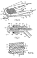
- the Venturi device 15 comprises a body 150 defining in its rear part an annular chamber 153 into which opens a nozzle 151 connected by a pipe 14 to the outlet 12 of the steam generator 103, to receive pure water vapor.
- a nozzle 152 also located at the rear of the Venturi 15 device allows the connection of the flexible pipe 16 for the supply of additive product and the application of this additive product to a central duct 155.
- a central part 156 comprising a part convergent for example frustoconical is arranged in the body 150 and allows the passage of steam from the annular chamber 153 in a converging annular space defined between the central part 156 and a external part of complementary shape 157.
- a central channel 155A is formed in the central part 156 in the extension of the central duct 155 to apply the additive to the center of the Venturi system in an area where the additive is sucked in by the water vapor introduced so concentric upstream of the central part 156 forming a convergent.
- the steam arriving in the chamber annular 153 creates, at the exit of the converging space created by the part central 156, a depression at the right of the arrival of additive liquid by the channel 155A, which allows this additive liquid to be sucked in and mixed with the steam at the outlet 158 of the head 159 of the Venturi device 15.
- the mixture is then propelled onto the surface to be cleaned through the cleaning head 107 which may include a brush 171 around the mixing dispenser in which opens the Venturi device 15.
- O-rings 154, 160 ensure the seal between the body 150 and the conduit 155 on the one hand and the central part 156 and complementary part 157 on the other hand.
- the additive liquid can be pure water serving both bomb the surface to be cleaned and entrain dirt removed by the combined action of steam and water, heated and projected by steam.
- the additive liquid can also be a detergent product, a perfume, a product bactericide or anticaricide.
- control mechanism 31, 32 selective feed of additive product allows the user to determine the cases where he wishes to obtain steam from the appliance alone, without additive, for example for cleaning smooth surfaces, and cases where it wishes to obtain a mixture of vapor and a liquid additive product or even powdery so as to increase the cleaning capacities.
- the device according to the invention makes it possible to combine the action of heat at will produced by water vapor with the action of an additive such as a product chemical detergent or pure water, which action is itself enhanced by the heat and the fact that the steam jet can bring the additive as close as possible particles to be cleaned.
- the user can also easily add according to the mechanical action required by the brush 171.
- the apparatus according to the invention is thus essentially an apparatus general public for domestic use suitable for cleaning surfaces hard and smooth such as windows, mirrors, tiles, ceramics, vitro-ceramics, walls of oven or sink, melamine furniture, than that of flexible and irregular surfaces such as textile seat coverings furniture or car or carpets or draperies.
- the cleaning device according to the invention has an efficiency increased compared to portable devices of the prior art, by the fact that it can, while remaining light, handy and inexpensive, produce instantaneous a significant flow of steam (for example 30 g of steam per minute), safely, regardless of the position of the device, and without scaling problems do not affect the operating capabilities of the device.
- An important aspect of the invention lies in the realization particularity of the steam generator 103 which, while being light, can provide a power greater than 1000 Watts.
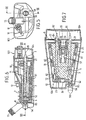
- FIGS. 3, 4, 6, 7, the space 3 has been identified in which finds the capillary body for storing, in divided form, the water reserve to evaporate, without representing this capillary body, for the clarity of the drawing.
- the Figure 10 shows an example of implementation of capillary body 3 constituted, for example, by rock wool fibers resistant to high temperatures. The fibers of the capillary body 3 are compressed by the perforated box 6, 7 around the heater 20 and provide a role at a time for storage of water to evaporate and thermal insulation between the heating body 20 and the plastic elements such as the housing 6, 7 itself.
- the steam generator 103 constitutes a generator of instantaneous production of steam, working at atmospheric pressure and comprises a heating body 20 constituted by an armored resistor 2 overmolded in a metallic material which conducts heat well, such as of aluminum, to favor the heat dissipation of the resistance 2.
- the armored resistor 2 has the shape of a U with two straight branches 21, 22 and an elbow 23 for connecting the two rectilinear branches 21, 22.
- the body heater 20 has a plate 25 located in a mean plane defined by armored resistor 2 and having a V shape flaring outward at the free ends of the straight branches 21, 22 of the armored resistance 2.
- This plate 25 which promotes the diffusion of heat and forms a unit with the semi-cylindrical metal parts overmolded on the armored resistor 2, may include an appendage 24, located for example in the vicinity of the curved part 23 of the resistor 2, for positioning in the housing 6, 7.
- the heating body 20 comprises ribs 26 (FIG. 8) arranged in the vicinity of the elbow 23 of the resistor 2, between the rectilinear branches 21, 22 of the resistor 2, in a zone 4 near the elbow 23 which constitutes the zone of greatest power density, in which warms up most quickly in the event of drying of the body capillary 3.
- zone 4 is highly exposed to premature drying due to the downward flow of water by gravity, by the action of the vapor formed below this zone and rising towards the steam outlet 12 by taking water in transit or by heating the water of the capillary body 3 coating this part 4.
- the capillary body of storage 3 may include a first layer 131 of oriented fibers in a plane parallel to the plane defined by the armored resistance 2 and perpendicular to the two straight branches 21, 22 of this resistor armored 2 in the zone 4 near the elbow 23 of the resistor 2 and corresponding to the presence of the ribs 26 of FIG. 8. This contributes to limit drying by simply flowing water from top to bottom.
- the capillary body 3 advantageously comprises a second sheet 132 of fibers oriented perpendicular to the plane defined by the resistance 2, in areas close to the two straight branches 21, 22 and away from the elbow 23 of the armored resistance.
- the shape of the two half-housings 6, 7 is complementary to that of the heating body 20 surrounded by the capillary body 3. It can thus be seen that the case 6, 7 flares outwards on the side opposite the elbow 23, to hold account of the widening of the plate 25 in the form of V.
- an element of rectilinear thermal transmission 51 is connected to the heater 20 vicinity of the internal part of the elbow 23 of the resistor 2, and ends by an end provided with a housing 53 in which a sensor is disposed thermal 55, which has been shown in Figure 7 but has been omitted in Figure 4 and FIG. 8.
- the thermal sensor has two pins 59 for connection for connection to regulating elements of the power supply resistance 2, which can be arranged in a separate compartment 104 adjacent to the sealed enclosure 10 of the steam generator 103.
- An elbow heat transfer element 52 is connected to the heating body 20 in the vicinity of the external part of the elbow 23 of the shielded resistor 2 and ends, outside the sealed enclosure 10, by one end provided with a housing 54 in which a sensor is disposed thermal 56, provided with two connection pins 58 for connection to elements for regulating the supply of resistor 2, placed in compartment 104, into which the power cord opens cleaning appliance (not shown in the drawings).
- the thermal sensor 56 has not been shown in FIG. 8.
- the thermal transmission elements 51, 52 constitute appendages which arise closest to the elbow 23 and may be produced by overmolding in the same material as the plate 25, as for example aluminum.
- the thermal sensors 55 and 56 such as thermostats, have different setpoints for better regulate the supply of the heating resistor 2 whose temperature increases rapidly as soon as the capillary body dries up in the zone 4 adjacent to the elbow 23.
- At least the rectilinear thermal transmission element 51, and the if necessary also the angled thermal transmission element 52 is advantageously thermally insulated by an external sheath made of a material thermally insulating, such as silicone, to avoid cooling by water not evaporated in the lower part possibly contained in the body capillary surrounding this thermal transmission element 51.
- the rectilinear branches 21, 22 of the resistor 2 pass through the wall of the enclosure 10 in a sealed manner using seals such as the seal 84, illustrated in Figure 7, in a material such as vitton or silicone.
- the compartment cover 104 can be ultrasonically welded to enclosure 10, once assembly is complete.
- the thermal sensors 55, 56 can be constituted by for example by thermostats, thermal probes, limiters or fuses.
- thermal sensors 55, 56 and elements of thermal transmission 51, 52 associated with a simple regulation circuit supply allows to implement a shielded resistance 2 in U of current type and of a power for example of 1200 Watts, without it an excessive risk of overheating ensues, even if in operation a part of the capillary body 3 dries up.
- the whole of the waterproof enclosure 10 and of the separate compartment 104 which constitutes the steam generator 103 is removable and allows easy replacement. Electrical connections within compartment 104 are well separated from the enclosure 10 where the water is stored in the body capillary 3 compressed by the perforated housing 6, 7 around the heater 20.
- Tap water is introduced by the input 13 which with the channel 13A is integral with the enclosure 10. Water permeates the capillary body 3 disposed in the perforated housing 6, 7 and excess water can be discharged through the inlet 13 by returning and shaking the device. After closing the plug 13B and connecting the electrical cord, the appliance is ready to operate.
- the regulation of resistor 2 can be supplied automatically so safe without operator intervention, thanks to the measures explained more high. After pressing the on-off button allowing regulated power supply of resistor 2 and therefore the production of steam, the operator simply has to decide whether or not to press the trigger 32, whether or not he wishes to have a mixture of steam and the product optional additive desired placed in tank 19 which may be transparent to check its contents and removable to facilitate its replacement.
- the user can at any time cut off the emission of steam by interrupting the electrical supply to resistor 2 using the button On Off.
Landscapes
- Engineering & Computer Science (AREA)
- Life Sciences & Earth Sciences (AREA)
- Sustainable Development (AREA)
- Sustainable Energy (AREA)
- Physics & Mathematics (AREA)
- Thermal Sciences (AREA)
- Mechanical Engineering (AREA)
- General Engineering & Computer Science (AREA)
- Cleaning By Liquid Or Steam (AREA)
- Cleaning In General (AREA)
Description
- la figure 1 est une vue d'ensemble, avec coupe partielle et une partie du boítier ôté, d'un exemple d'appareil portable de nettoyage à la vapeur selon l'invention,
- la figure 2 est une vue de face de l'appareil de la figure 1, la tête de nettoyage ayant été ôtée, ainsi qu'une moitié du boítier pour laisser apparaítre le générateur de vapeur,
- la figure 3 est une vue en coupe selon la ligne III-III de la figure 2,
- la figure 4 est une vue en coupe selon la ligne IV-IV de la figure 3,
- la figure 5 est une vue de face du seul générateur de vapeur incorporé dans l'appareil des figures 1 à 4,
- la figure 6 est une vue en coupe selon la ligne VI-VI de la figure 5,
- la figure 7 est une vue en coupe selon la ligne VII-VII de la figure 6,
- la figure 8 est une vue en perspective d'un corps de chauffe selon l'invention adapté au générateur de vapeur des figures 5 à 7 et à l'appareil de nettoyage des figures 1 à 4,
- la figure 9 est une vue en coupe d'un système Venturi pouvant être incorporé dans un appareil de nettoyage selon l'invention et permettant d'assurer le mélange d'un produit additif avec de la vapeur, et
- la figure 10 est une vue schématique de dessus, montrant un exemple d'agencement possible d'un corps capillaire autour d'un corps de chauffe dans un générateur de vapeur instantanée incorporé dans un appareil de nettoyage portable omnidirectionnel selon l'invention.
Claims (25)
- Appareil portable omnidirectionnel pour le nettoyage à la vapeur de surfaces aussi bien dures que souples, comprenant un boítier (101) muni d'une poignée (102), un orifice (13) d'alimentation en eau, un cordon d'alimentation électrique, une tête de nettoyage (107), un générateur de vapeur (103) intégré dans le boítier (101) et comportant des moyens (3) de stockage d'une réserve d'eau et des moyens électriques (2) de chauffage de cette réserve d'eau (3) pour produire de la vapeur d'eau, et des moyens (14, 15) pour distribuer sélectivement de la vapeur d'eau à la tête de nettoyage (107),
l'appareil portable comprenant un générateur (103) de vapeur instantanée à faible inertie thermique travaillant à la pression atmosphérique et comprenant un corps capillaire (3) de stockage sous forme divisée, de la totalité de la réserve d'eau à évaporer, le corps capillaire (3) étant comprimé autour des moyens électriques de chauffage qui comprennent une résistance blindée (2) surmoulée dans un matériau métallique bon conducteur de la chaleur pour former un corps de chauffe (20), auquel est associé au moins un élément de transmission thermique (51, 52) qui est raccordé à la partie la plus chaude (23) du corps de chauffe (20) et est muni d'un capteur thermique (55, 56) permettant d'optimiser le pilotage de l'alimentation de la résistance blindée (2) et sa mise en sécurité quelle que soit l'orientation dans l'espace du générateur de vapeur (103). - Appareil selon la revendication 1, caractérisé en ce que la résistance blindée (2) présente la forme d'un U avec deux branches rectilignes (21, 22) et un coude (23) de raccordement des deux branches rectilignes (21, 22).
- Appareil selon la revendication 2, caractérisé en ce qu'il comprend un élément de transmission thermique (51) rectiligne raccordé au corps de chauffe (20) au voisinage de la partie interne du coude (23) de la résistance blindée (2) en forme de U, et muni d'un capteur thermique (55).
- Appareil selon la revendication 2 ou la revendication 3, caractérisé en ce qu'il comprend un élément de transmission thermique (52) raccordé au corps de chauffe (20) au voisinage de la partie externe du coude (23) de la résistance blindée (2) en forme de U, et muni d'un capteur thermique (56).
- Appareil selon les revendications 3 et 4, caractérisé en ce que les premier et deuxième capteurs thermiques (55, 56) associés aux éléments de transmission thermique (51, 52) raccordés au voisinage des parties interne et externe du coude (23) de la résistance blindée (2) présentent des valeurs de consigne différentes.
- Appareil selon l'une quelconque des revendications 2 à 5, caractérisé en ce que le corps de chauffe (20) comprend des nervures (26) disposées au voisinage du coude (23) de la résistance blindée (2), entre les branches rectilignes (21, 22) de cette résistance blindée (2).
- Appareil selon l'une quelconque des revendications 2 à 6, caractérisé en ce que le corps capillaire de stockage (3) comprend une première nappe (131) de fibres orientées dans un plan parallèle au plan défini par la résistance blindée (2) et perpendiculairement aux deux branches rectilignes (21, 22) de cette résistance blindée (2), dans une zone (4) voisine du coude (23) de la résistance blindée (2).
- Appareil selon l'une quelconque des revendications 2 à 7, caractérisé en ce que le corps capillaire de stockage (3) comprend une deuxième nappe (132) de fibres orientées perpendiculairement au plan défini par la résistance blindée (2), dans des zones proches des deux branches rectilignes (21, 22) et éloignées du coude (23) de la résistance blindée (2).
- Appareil selon les revendications 7 et 8, caractérisé en ce que la première nappe (131) du corps capillaire de stockage (3) située dans une zone (4) voisine du coude (23) de la résistance (2) comprend une compression ou un volume plus importants que la deuxième nappe (132).
- Appareil selon l'une quelconque des revendications 1 à 9, caractérisé en ce que chaque élément de transmission thermique (51, 52) est entouré d'un matériau isolant thermiquement, dans sa portion en contact avec le corps poreux capillaire.
- Appareil selon l'une quelconque des revendications 1 à 10, caractérisé en ce que la résistance blindée (2) présente une puissance comprise entre 1000 et 1500 Watts.
- Appareil selon l'une quelconque des revendications 1 à 11, caractérisé en ce que le générateur de vapeur (103) comprend une première enceinte (10) étanche et amovible dans laquelle débouche l'orifice (13) d'alimentation en eau, dans laquelle prend naissance un conduit primaire (12) de distribution de vapeur d'eau et à l'intérieur de laquelle se trouve une deuxième enceinte (6, 7) munie de perforations (61, 71) et assurant une compression du corps capillaire de stockage (3) autour du corps de chauffe (20).
- Appareil selon l'une quelconque des revendications 1 à 12, caractérisé en ce que le matériau métallique bon conducteur de la chaleur dans lequel est surmoulée la résistance blindée (2) est constitué par de l'aluminium.
- Appareil selon l'une quelconque des revendications 1 à 3, caractérisé en ce que le capteur thermique (55, 56) associé à un élément de transmission thermique (51, 52) est constitué par l'un des éléments suivants : thermostat, sonde thermique, limiteur thermique, fusible.
- Appareil selon l'une quelconque des revendications 1 à 14, caractérisé en ce que le corps capillaire (3) de stockage est constitué par des fibres de laine de roche.
- Appareil selon l'une quelconque des revendications 2 à 9, caractérisé en ce que le corps de chauffe (20) comporte une plaque (25) située dans un plan moyen défini par la résistance blindée (2) et présentant une forme de V s'évasant vers l'extérieur au niveau des extrémités libres des branches rectilignes (21, 22) de la résistance blindée (2).
- Appareil selon l'une quelconque des revendications 1 à 16, caractérisé en ce qu'il comprend un boítier (101) présentant une face inférieure (106) sensiblement plane, une face arrière (108) formant talon, une face supérieure munie d'une ouverture (102) définissant une poignée en forme d'anse (102A) et une extrémité avant de section réduite à laquelle est raccordée la tête de nettoyage (107).
- Appareil selon l'une quelconque des revendications 1 à 17, caractérisé en ce qu'il comprend en outre un réservoir (19) de produit additif liquide ou pulvérulent incorporé dans le boítier (101) et relié par une conduite (16) à un système Venturi (15) d'introduction du produit additif dans de la vapeur produite dans le générateur de vapeur (103) pour appliquer à la tête de nettoyage (107) un mélange de vapeur et de produit additif.
- Appareil selon les revendications 17 et 18, caractérisé en ce que le réservoir (19) de produit additif est placé à l'intérieur du boítier (101) derrière la poignée en forme d'anse (102A), en ce que le système Venturi (15) est disposé dans le boítier (101) au voisinage de la tête de nettoyage (107), en ce que la conduite (16) de liaison entre le réservoir (19) de produit additif et le système Venturi (15) traverse la poignée (102A) en forme d'anse et en ce qu'un moyen (31, 32) de commande d'alimentation sélective en produit additif est disposé dans la poignée (102A) en forme d'anse.
- Appareil selon la revendication 19, caractérisé en ce que la conduite (16) de liaison entre le réservoir (19) de produit additif et le système Venturi (15) est constituée en une matière souple telle que du caoutchouc et en ce que le moyen de commande d'alimentation sélective en produit additif comprend un dispositif (31) de pincement de ladite conduite (16) et une gâchette manuelle (32) de déblocage temporaire du dispositif (31) de pincement.
- Appareil selon l'une quelconque des revendications 18 à 20, caractérisé en ce que la conduite (16) de transport de produit additif débouche au centre du système Venturi (15) de telle manière que le produit additif soit aspiré par la vapeur d'eau qui a été introduite dans le système Venturi (15) de façon concentrique en amont d'une pièce (156) formant convergent.
- Appareil selon les revendications 2 et 12, caractérisé en ce que le générateur de vapeur (103) présente un orifice (13) d'alimentation en eau qui débouche au voisinage du coude (23) de la résistance blindée (2), et un conduit primaire (12) de distribution de vapeur situé dans une partie centrale surélevée de la première enceinte (10).
- Appareil selon l'une quelconque des revendications 1 à 22, caractérisé en ce que la tête de nettoyage comprend un organe (171) en forme de brosse au centre duquel est distribuée la vapeur d'eau produite par le générateur de vapeur intégré (103).
- Appareil selon l'une quelconque des revendications 1 à 23, caractérisé en ce qu'il constitue un appareil d'utilisation domestique appliqué au nettoyage de surfaces dures telles que vitres, glaces, carrelages, céramiques, vitro-céramiques aussi bien que de surfaces souples telles que des revêtements textiles de sièges d'ameublement ou de voiture, ou des tapis.
- Appareil selon l'une quelconque des revendications 18 à 21, caractérisé en ce que le produit additif est sous forme liquide et comprend l'un des produits constitués par de l'eau pure, un produit détergent, un parfum, un produit bactéricide ou un produit anticaricide.
Applications Claiming Priority (2)
| Application Number | Priority Date | Filing Date | Title |
|---|---|---|---|
| FR9705226A FR2762531B1 (fr) | 1997-04-28 | 1997-04-28 | Appareil portable omnidirectionnel de nettoyage a la vapeur de surfaces dures ou souples |
| FR9705226 | 1997-04-28 |
Publications (2)
| Publication Number | Publication Date |
|---|---|
| EP0875194A1 EP0875194A1 (fr) | 1998-11-04 |
| EP0875194B1 true EP0875194B1 (fr) | 2003-03-19 |
Family
ID=9506375
Family Applications (1)
| Application Number | Title | Priority Date | Filing Date |
|---|---|---|---|
| EP98401033A Expired - Lifetime EP0875194B1 (fr) | 1997-04-28 | 1998-04-28 | Appareil portable de nettoyage à la vapeur de surfaces dures ou souples |
Country Status (5)
| Country | Link |
|---|---|
| US (1) | US6031969A (fr) |
| EP (1) | EP0875194B1 (fr) |
| DE (1) | DE69812212T2 (fr) |
| ES (1) | ES2196509T3 (fr) |
| FR (1) | FR2762531B1 (fr) |
Cited By (2)
| Publication number | Priority date | Publication date | Assignee | Title |
|---|---|---|---|---|
| DE10351878B3 (de) * | 2003-10-29 | 2005-04-21 | Alfred Kärcher Gmbh & Co. Kg | Dampferzeuger sowie Dampfreinigungsgerät mit einem Dampferzeuger |
| CN105581743A (zh) * | 2014-11-07 | 2016-05-18 | 百得有限公司 | 蒸汽清洁装置和配件 |
Families Citing this family (63)
| Publication number | Priority date | Publication date | Assignee | Title |
|---|---|---|---|---|
| IT1296721B1 (it) * | 1997-11-26 | 1999-07-15 | Vetrella Spa | Apparecchio di pulizia a vapore |
| DE29822527U1 (de) * | 1998-12-17 | 1999-02-11 | Tsai, Sam, Taipeh/T'ai-pei | Multifunktioneller, elektrischer Dampfreiniger |
| IT1310957B1 (it) * | 1999-06-07 | 2002-02-27 | Gen Technology S R L | Attrezzo a vapore ad uso domestico dotato di dispositivo didisincrostazione ad azionamento manuale o automatico. |
| USD443960S1 (en) | 2000-01-12 | 2001-06-19 | Royal Appliance Mfg. Co. | Portable wet/dry vacuum cleaner |
| US6347428B1 (en) | 2000-01-12 | 2002-02-19 | Royal Appliance Mfg. Co. | Hand-held wet/dry vacuum |
| USD445972S1 (en) | 2000-08-01 | 2001-07-31 | Termozeta S.P.A. | Steam cleaning domestic apparatus |
| US6502275B1 (en) * | 2000-11-27 | 2003-01-07 | Ye Jen Co., Ltd | Anti-explosion steam vacuum cleaner heating structure |
| USD465886S1 (en) | 2001-08-14 | 2002-11-19 | Termozeta S.P.A. | Steam generating domestic appliance |
| US6986217B2 (en) * | 2002-01-09 | 2006-01-17 | Conair Corporation | Hand held garment steamer |
| US6934995B2 (en) * | 2002-06-19 | 2005-08-30 | Black & Decker Inc. | Hand held steam vacuum with single switch operation |
| US6839933B2 (en) * | 2002-06-19 | 2005-01-11 | Black & Decker Inc. | Fluid supply tank for hand held vacuum |
| USD475164S1 (en) | 2002-06-19 | 2003-05-27 | Black & Decker Inc. | Steam vacuum cleaner |
| US6895632B2 (en) * | 2002-06-19 | 2005-05-24 | Black & Decker Inc. | Hand held vacuum with arcuate gliding surface |
| US6886373B2 (en) * | 2002-09-13 | 2005-05-03 | Conair Corporation | Garment steamer |
| US7225503B1 (en) | 2002-11-27 | 2007-06-05 | Bissell Homecare, Inc. | Hand-held deep cleaner |
| US20060018638A1 (en) * | 2003-01-09 | 2006-01-26 | Leung Anthony K L | Hand held garment steamer |
| US7478455B2 (en) * | 2003-01-10 | 2009-01-20 | Lisa Ann Heim | Hand-held clothing spot remover |
| ATE463176T1 (de) * | 2003-02-13 | 2010-04-15 | Black & Decker Inc | Tragbare schrubbvorrichtung |
| DE10310251B3 (de) * | 2003-03-04 | 2004-07-01 | Alfred Kärcher Gmbh & Co. Kg | Dampfreinigungsgerät |
| US7304278B2 (en) * | 2003-03-13 | 2007-12-04 | Matsushita Electric Industrial Co., Ltd. | Steam generation function-equipped high-frequency heating device |
| USD506297S1 (en) * | 2003-06-11 | 2005-06-14 | Buzzi S.R.L. | Steam gun |
| WO2005018837A1 (fr) * | 2003-08-23 | 2005-03-03 | Technoscience Integrated Technology Appliances Pte Ltd | Dispositif d'assainissement portatif |
| GB2415695A (en) | 2004-07-02 | 2006-01-04 | Reckitt Benckiser Nv | Detergent composition comprising a chelating agent |
| GB0415516D0 (en) * | 2004-07-10 | 2004-08-11 | Reckitt Benckiser Nv | Apparatus and method of using the same |
| USD519694S1 (en) * | 2004-07-23 | 2006-04-25 | Euro-Pro Corporation | Surface configuration of a steam cleaner |
| US7414337B2 (en) * | 2005-03-14 | 2008-08-19 | Black & Decker Inc. | Scrubber |
| KR100748713B1 (ko) | 2005-10-24 | 2007-08-13 | (주)정신전자 | 스팀청소기 |
| GB0603314D0 (en) * | 2006-02-20 | 2006-03-29 | Sun Brian | Steam Generator |
| US20070209139A1 (en) * | 2006-03-09 | 2007-09-13 | Carlucci Vito J | Steam cleaner with liquid dispenser |
| US20080022480A1 (en) * | 2006-07-28 | 2008-01-31 | Main Power Electrical Factory Ltd. | Handheld steam cleaner |
| WO2008016262A2 (fr) * | 2006-08-02 | 2008-02-07 | Lg Electronics Inc. | Machine à laver |
| US7937792B2 (en) * | 2006-10-19 | 2011-05-10 | Black & Decker Inc. | Pole scrubber |
| USD626708S1 (en) | 2008-03-11 | 2010-11-02 | Royal Appliance Mfg. Co. | Hand vacuum |
| US8534301B2 (en) | 2008-06-02 | 2013-09-17 | Innovation Direct Llc | Steam mop |
| US20090313767A1 (en) * | 2008-06-22 | 2009-12-24 | Antimicrobial Test Laboratories, Llc | Cordless Battery Operated Handheld Steamer and Methods of Operation |
| BRPI0919686A2 (pt) * | 2008-10-22 | 2021-04-20 | Rosemount Inc | sensor/transmissor plug-and-play para instrumentação de processo |
| CN201317890Y (zh) * | 2008-12-12 | 2009-09-30 | 漳州灿坤实业有限公司 | 一种多功能电熨斗 |
| FR2954360B1 (fr) * | 2009-12-17 | 2014-06-27 | Seb Sa | Appareil de repassage a la vapeur comportant une brosse de defroissage |
| AU2010249272C1 (en) * | 2009-12-18 | 2014-07-17 | Bissell Inc. | Dry vacuum cleaner with spot cleaning |
| USD646861S1 (en) * | 2011-01-03 | 2011-10-11 | Euro-Pro Operating Llc | Handheld cleaning appliance |
| US10426304B2 (en) * | 2011-11-08 | 2019-10-01 | Hydramaster, Llc | Portable extractor machine |
| USD712608S1 (en) * | 2012-08-24 | 2014-09-02 | Black & Decker Inc. | Steam cleaning brush |
| USD712609S1 (en) * | 2012-08-24 | 2014-09-02 | Black & Decker Inc. | Steam cleaning brush |
| WO2014159513A1 (fr) * | 2013-03-14 | 2014-10-02 | Gumwand, Inc. | Appareil à vapeur permettant de retirer de la gomme et analogues de diverses surfaces |
| US10238261B2 (en) * | 2013-03-14 | 2019-03-26 | Gumwand, Inc. | Steamer for removing gum and the like from various surfaces |
| GB2536831A (en) * | 2013-07-01 | 2016-09-28 | Techtronic Floor Care Tech Ltd | Surface cleaning apparatus |
| WO2015135101A1 (fr) | 2014-03-10 | 2015-09-17 | Conair Corporation | Système de traitement de vêtement |
| DE202014010679U1 (de) | 2014-06-25 | 2016-04-08 | Alfred Kärcher Gmbh & Co. Kg | Hand-Dampfgerät |
| DE202014010671U1 (de) | 2014-06-25 | 2016-04-06 | Alfred Kärcher Gmbh & Co. Kg | Hand-Dampfgerät |
| DE202014010673U1 (de) | 2014-06-25 | 2016-04-06 | Alfred Kärcher Gmbh & Co. Kg | Hand-Dampfgerät |
| KR200488988Y1 (ko) | 2014-12-08 | 2019-04-12 | 콘에어 코포레이션 | 이동식 휴대용 스팀다리미 장치 |
| US10869502B2 (en) * | 2015-07-31 | 2020-12-22 | 14Th Round Inc. | Disposable assembly for vaporizing e-liquid and a method of using the same |
| CN205143486U (zh) * | 2015-09-02 | 2016-04-13 | 深圳市合元科技有限公司 | 雾化头、雾化器及电子烟 |
| US10851771B2 (en) * | 2016-07-29 | 2020-12-01 | Beijing China Base Startrade Co., Ltd. | Portable battery steam cleaner |
| USD848093S1 (en) * | 2016-10-17 | 2019-05-07 | Unger Marketing International, Llc | Hard surface cleaning device |
| FR3060027B1 (fr) * | 2016-12-13 | 2018-11-23 | Seb S.A. | Appareil de defroissage a la vapeur |
| EP3875015B1 (fr) | 2017-01-31 | 2025-04-16 | Bissell Inc. | Appareil de nettoyage à la vapeur |
| USD878697S1 (en) | 2019-02-19 | 2020-03-17 | Hamilton Beach Brands, Inc. | Iron |
| US11655585B2 (en) | 2019-04-16 | 2023-05-23 | Hamilton Beach Brands, Inc. | Iron-steamer appliance |
| USD984072S1 (en) * | 2021-06-22 | 2023-04-18 | Bissell Inc. | Portable carpet cleaner |
| US20250072697A1 (en) * | 2021-07-27 | 2025-03-06 | Lg Electronics Inc. | Mop module of cleaner |
| USD1025521S1 (en) * | 2021-11-16 | 2024-04-30 | Bissell Inc. | Portable carpet cleaner |
| CN116300902A (zh) * | 2023-02-17 | 2023-06-23 | 深圳优地科技有限公司 | 配送机器人通知方法、电子设备和存储介质 |
Family Cites Families (12)
| Publication number | Priority date | Publication date | Assignee | Title |
|---|---|---|---|---|
| US2588000A (en) * | 1946-01-29 | 1952-03-04 | Hines Albert Roy | Suction cleaner with brush for cleaning walls |
| US2849736A (en) * | 1955-05-16 | 1958-09-02 | Albert G Kohle | Fabric steaming and brushing device |
| AT303300B (de) * | 1970-07-27 | 1972-11-27 | Anton Drazdal | Gerät zum Reinigen von Flächen, insbesondere Scheiben |
| FR2218867A2 (fr) * | 1973-02-23 | 1974-09-20 | Vap Clean Sa | |
| FR2230322A1 (en) * | 1973-05-23 | 1974-12-20 | Frischmann Walter | Electrically powered wash device for windows - has coil in sponge whose face is covered by grid formed as grid |
| AT350677B (de) * | 1976-01-19 | 1979-06-11 | Unitherm Oesterreich Gmbh | Elektrischer heizeinsatz |
| CH658356A5 (de) * | 1982-12-08 | 1986-10-31 | Jura Elektroapparate Fab | Heizvorrichtung und verfahren zur herstellung derselben. |
| US5341541A (en) * | 1992-09-09 | 1994-08-30 | Sham John C K | Portable steam vacuum cleaner |
| US5367740A (en) * | 1993-07-21 | 1994-11-29 | Mccray; Kimothy R. | Hand-held surface cleaning apparatus |
| IT234928Y1 (it) * | 1994-03-15 | 2000-03-20 | Interpump Spa | Attrezzo pulitore domestico a vapore. |
| KR19980701703A (ko) * | 1995-02-01 | 1998-06-25 | 폴 리비에르 | 방열판을 구비한 가열 요소와 그 조립 방법 |
| FR2742682B1 (fr) * | 1995-12-22 | 1998-03-13 | Superba Sa | Appareil electrique de nettoyage a la vapeur d'eau de surfaces lisses telles que des vitres |
-
1997
- 1997-04-28 FR FR9705226A patent/FR2762531B1/fr not_active Expired - Fee Related
-
1998
- 1998-03-30 US US09/050,691 patent/US6031969A/en not_active Expired - Fee Related
- 1998-04-28 ES ES98401033T patent/ES2196509T3/es not_active Expired - Lifetime
- 1998-04-28 DE DE69812212T patent/DE69812212T2/de not_active Expired - Fee Related
- 1998-04-28 EP EP98401033A patent/EP0875194B1/fr not_active Expired - Lifetime
Cited By (6)
| Publication number | Priority date | Publication date | Assignee | Title |
|---|---|---|---|---|
| DE10351878B3 (de) * | 2003-10-29 | 2005-04-21 | Alfred Kärcher Gmbh & Co. Kg | Dampferzeuger sowie Dampfreinigungsgerät mit einem Dampferzeuger |
| CN105581743A (zh) * | 2014-11-07 | 2016-05-18 | 百得有限公司 | 蒸汽清洁装置和配件 |
| CN105581744A (zh) * | 2014-11-07 | 2016-05-18 | 百得有限公司 | 蒸汽清洁装置及配件 |
| CN105581745B (zh) * | 2014-11-07 | 2018-05-04 | 百得有限公司 | 蒸汽清洁装置和配件 |
| CN105581743B (zh) * | 2014-11-07 | 2018-05-22 | 百得有限公司 | 蒸汽清洁装置和配件 |
| CN105581744B (zh) * | 2014-11-07 | 2018-06-01 | 百得有限公司 | 蒸汽清洁装置及配件 |
Also Published As
| Publication number | Publication date |
|---|---|
| FR2762531A1 (fr) | 1998-10-30 |
| ES2196509T3 (es) | 2003-12-16 |
| EP0875194A1 (fr) | 1998-11-04 |
| DE69812212D1 (de) | 2003-04-24 |
| US6031969A (en) | 2000-02-29 |
| DE69812212T2 (de) | 2003-12-11 |
| FR2762531B1 (fr) | 1999-08-13 |
Similar Documents
| Publication | Publication Date | Title |
|---|---|---|
| EP0875194A1 (fr) | Appareil portable de nettoyage à la vapeur de surfaces dures ou souples | |
| EP3555359B1 (fr) | Appareil de défroissage à la vapeur | |
| EP2503052B1 (fr) | Fer à repasser à vapeur comportant une plaque de repassage comprenant au moins un premier groupe et un deuxième groupe de trous de sortie de vapeur | |
| EP2705190B1 (fr) | Appareil de repassage comportant un fer a repasser sans fil et une base de recharge | |
| EP0780083B1 (fr) | Appareil électrique de nettoyage à la vapeur d'eau de surfaces lisses telles que des vitres | |
| EP2808438B1 (fr) | Appareil de repassage à la vapeur comprenant un fer à repasser | |
| CA2835785C (fr) | Appareil de repassage a la vapeur comportant un generateur de vapeur sous pression et un fer a repasser | |
| FR3072100A1 (fr) | Appareil de defroissage equipe d'une chambre de vaporisation munie d'un orifice de nettoyage | |
| FR2979924A1 (fr) | Appareil electromenager comportant un circuit de distribution de vapeur | |
| EP1006849B1 (fr) | Appareil de cuisson electrique comportant un dispositif de condensation des vapeurs de cuisson | |
| WO2008099266A1 (fr) | Appareil de repassage a vapeur comportant un reservoir d' eau en communication directe avec une chambre d' ebullition | |
| EP2705189B1 (fr) | Fer à repasser comportant un bouton de commande de la vapeur | |
| EP2808439B1 (fr) | Appareil de repassage à la vapeur | |
| FR2979922A1 (fr) | Appareil de repassage comportant un circuit de distribution de vapeur | |
| WO2008099265A1 (fr) | Appareil de repassage comportant une chambre d'ebullition dans laquelle la vapeur produite peut s'echapper librement vers un organe de repassage | |
| FR3107533A1 (fr) | Appareil de défroissage portatif | |
| EP4105378B1 (fr) | Appareil de defroissage portatif comprenant une poignee renfermant un conduit de vapeur | |
| EP4092181B1 (fr) | Appareil de defroissage portatif comprenant une poignee renfermant un conduit de vapeur | |
| FR2670660A1 (fr) | Bouilloire electrique a chauffage ameliore. | |
| EP3985167A1 (fr) | Appareil de defroissage portatif comportant un dispositif de diffusion d'un additif | |
| EP3336244A1 (fr) | Fer a repasser comportant une surface de repassage, une semelle chauffante et une chambre de vaporisation |
Legal Events
| Date | Code | Title | Description |
|---|---|---|---|
| PUAI | Public reference made under article 153(3) epc to a published international application that has entered the european phase |
Free format text: ORIGINAL CODE: 0009012 |
|
| AK | Designated contracting states |
Kind code of ref document: A1 Designated state(s): DE ES GB IT NL |
|
| AX | Request for extension of the european patent |
Free format text: AL;LT;LV;MK;RO;SI |
|
| 17P | Request for examination filed |
Effective date: 19990210 |
|
| AKX | Designation fees paid |
Free format text: DE ES GB IT NL |
|
| RAP1 | Party data changed (applicant data changed or rights of an application transferred) |
Owner name: DOMENA |
|
| GRAG | Despatch of communication of intention to grant |
Free format text: ORIGINAL CODE: EPIDOS AGRA |
|
| 17Q | First examination report despatched |
Effective date: 20020620 |
|
| GRAG | Despatch of communication of intention to grant |
Free format text: ORIGINAL CODE: EPIDOS AGRA |
|
| GRAH | Despatch of communication of intention to grant a patent |
Free format text: ORIGINAL CODE: EPIDOS IGRA |
|
| GRAH | Despatch of communication of intention to grant a patent |
Free format text: ORIGINAL CODE: EPIDOS IGRA |
|
| GRAA | (expected) grant |
Free format text: ORIGINAL CODE: 0009210 |
|
| AK | Designated contracting states |
Designated state(s): DE ES GB IT NL |
|
| PG25 | Lapsed in a contracting state [announced via postgrant information from national office to epo] |
Ref country code: NL Free format text: LAPSE BECAUSE OF FAILURE TO SUBMIT A TRANSLATION OF THE DESCRIPTION OR TO PAY THE FEE WITHIN THE PRESCRIBED TIME-LIMIT Effective date: 20030319 |
|
| REG | Reference to a national code |
Ref country code: GB Ref legal event code: FG4D Free format text: NOT ENGLISH |
|
| REF | Corresponds to: |
Ref document number: 69812212 Country of ref document: DE Date of ref document: 20030424 Kind code of ref document: P |
|
| GBT | Gb: translation of ep patent filed (gb section 77(6)(a)/1977) | ||
| NLV1 | Nl: lapsed or annulled due to failure to fulfill the requirements of art. 29p and 29m of the patents act | ||
| REG | Reference to a national code |
Ref country code: ES Ref legal event code: FG2A Ref document number: 2196509 Country of ref document: ES Kind code of ref document: T3 |
|
| PLBE | No opposition filed within time limit |
Free format text: ORIGINAL CODE: 0009261 |
|
| STAA | Information on the status of an ep patent application or granted ep patent |
Free format text: STATUS: NO OPPOSITION FILED WITHIN TIME LIMIT |
|
| 26N | No opposition filed |
Effective date: 20031222 |
|
| PGFP | Annual fee paid to national office [announced via postgrant information from national office to epo] |
Ref country code: DE Payment date: 20050408 Year of fee payment: 8 |
|
| PGFP | Annual fee paid to national office [announced via postgrant information from national office to epo] |
Ref country code: ES Payment date: 20050414 Year of fee payment: 8 |
|
| PGFP | Annual fee paid to national office [announced via postgrant information from national office to epo] |
Ref country code: GB Payment date: 20050415 Year of fee payment: 8 |
|
| PG25 | Lapsed in a contracting state [announced via postgrant information from national office to epo] |
Ref country code: GB Free format text: LAPSE BECAUSE OF NON-PAYMENT OF DUE FEES Effective date: 20060428 |
|
| PG25 | Lapsed in a contracting state [announced via postgrant information from national office to epo] |
Ref country code: ES Free format text: LAPSE BECAUSE OF NON-PAYMENT OF DUE FEES Effective date: 20060429 |
|
| PGFP | Annual fee paid to national office [announced via postgrant information from national office to epo] |
Ref country code: IT Payment date: 20060430 Year of fee payment: 9 |
|
| PG25 | Lapsed in a contracting state [announced via postgrant information from national office to epo] |
Ref country code: DE Free format text: LAPSE BECAUSE OF NON-PAYMENT OF DUE FEES Effective date: 20061101 |
|
| GBPC | Gb: european patent ceased through non-payment of renewal fee |
Effective date: 20060428 |
|
| REG | Reference to a national code |
Ref country code: ES Ref legal event code: FD2A Effective date: 20060429 |
|
| PG25 | Lapsed in a contracting state [announced via postgrant information from national office to epo] |
Ref country code: IT Free format text: LAPSE BECAUSE OF NON-PAYMENT OF DUE FEES Effective date: 20070428 |