EP0874167A1 - Expansion dowel - Google Patents
Expansion dowel Download PDFInfo
- Publication number
- EP0874167A1 EP0874167A1 EP98103853A EP98103853A EP0874167A1 EP 0874167 A1 EP0874167 A1 EP 0874167A1 EP 98103853 A EP98103853 A EP 98103853A EP 98103853 A EP98103853 A EP 98103853A EP 0874167 A1 EP0874167 A1 EP 0874167A1
- Authority
- EP
- European Patent Office
- Prior art keywords
- expansion
- sleeve
- tongues
- expansion sleeve
- shaft
- Prior art date
- Legal status (The legal status is an assumption and is not a legal conclusion. Google has not performed a legal analysis and makes no representation as to the accuracy of the status listed.)
- Granted
Links
- 210000002105 tongue Anatomy 0.000 claims abstract description 54
- 238000003892 spreading Methods 0.000 claims description 28
- 238000013459 approach Methods 0.000 claims description 3
- 230000007704 transition Effects 0.000 claims description 3
- 230000000149 penetrating effect Effects 0.000 claims description 2
- 238000004873 anchoring Methods 0.000 description 9
- 238000011161 development Methods 0.000 description 7
- 238000006073 displacement reaction Methods 0.000 description 5
- 238000005336 cracking Methods 0.000 description 3
- 239000002184 metal Substances 0.000 description 3
- 238000012549 training Methods 0.000 description 2
- 238000005452 bending Methods 0.000 description 1
- 230000000903 blocking effect Effects 0.000 description 1
- 238000007664 blowing Methods 0.000 description 1
- 230000000694 effects Effects 0.000 description 1
- 238000004049 embossing Methods 0.000 description 1
- 238000004880 explosion Methods 0.000 description 1
- 238000003780 insertion Methods 0.000 description 1
- 230000037431 insertion Effects 0.000 description 1
- 238000004519 manufacturing process Methods 0.000 description 1
- 238000000034 method Methods 0.000 description 1
- 238000004080 punching Methods 0.000 description 1
Images


Classifications
-
- F—MECHANICAL ENGINEERING; LIGHTING; HEATING; WEAPONS; BLASTING
- F16—ENGINEERING ELEMENTS AND UNITS; GENERAL MEASURES FOR PRODUCING AND MAINTAINING EFFECTIVE FUNCTIONING OF MACHINES OR INSTALLATIONS; THERMAL INSULATION IN GENERAL
- F16B—DEVICES FOR FASTENING OR SECURING CONSTRUCTIONAL ELEMENTS OR MACHINE PARTS TOGETHER, e.g. NAILS, BOLTS, CIRCLIPS, CLAMPS, CLIPS OR WEDGES; JOINTS OR JOINTING
- F16B13/00—Dowels or other devices fastened in walls or the like by inserting them in holes made therein for that purpose
- F16B13/04—Dowels or other devices fastened in walls or the like by inserting them in holes made therein for that purpose with parts gripping in the hole or behind the reverse side of the wall after inserting from the front
- F16B13/06—Dowels or other devices fastened in walls or the like by inserting them in holes made therein for that purpose with parts gripping in the hole or behind the reverse side of the wall after inserting from the front combined with expanding sleeve
- F16B13/063—Dowels or other devices fastened in walls or the like by inserting them in holes made therein for that purpose with parts gripping in the hole or behind the reverse side of the wall after inserting from the front combined with expanding sleeve by the use of an expander
- F16B13/065—Dowels or other devices fastened in walls or the like by inserting them in holes made therein for that purpose with parts gripping in the hole or behind the reverse side of the wall after inserting from the front combined with expanding sleeve by the use of an expander fastened by extracting the screw, nail or the like
Definitions
- the invention relates to an expansion anchor with the features of the preamble of Claim 1.
- Such an expansion anchor is known from DE 31 46 027 A1.
- the known Expansion dowel has an expansion sleeve, on the through from a front end attached longitudinal slots are formed tongues.
- At the front end of the Spreading sleeve is an expanding expanding body arranged by expanding the Spreading tongues on the expansion body spread these apart radially. The upsetting is done by driving the expansion sleeve axially into the borehole. Of the Spreading body must sit on a screed base.
- the known expansion anchor is particularly suitable for setting in a cylindrical borehole provided in concrete.
- the spread tongues When the spread tongues are spread out, they form in the area their front end edges in a borehole wall, so that an undercut in Borehole is formed.
- the expansion anchor is pressed in radially Spread tongues on the borehole wall non-positively and by reaching behind the from Undercut caused by anchoring anchored positively in the borehole.
- the known expansion dowel has the disadvantage that to produce the undercut a high spreading force is necessary. Another disadvantage is that the expansion body on the The bottom of the borehole must sit to drive the expansion sleeve onto it and thereby to be able to spread. That is why there is a borehole on the expansion dowel coordinated depth necessary.
- the invention has for its object a expansion plug of the aforementioned Kind so that the for spreading and producing the undercut in Borehole necessary spreading force is reduced.
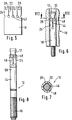
- FIG. 1 Show front end edges of the expansion tongues of the expansion dowel according to the invention Recesses on, so that standing teeth on the expansion tongues are formed are.
- the teeth can be rectangular, triangular or in side view, for example be dovetailed.
- a spreading tongue can have one or more teeth exhibit.
- the expansion tongues are on their front Frontal edges, i.e. where the spreading begins and is greatest, narrower. This increases the surface load on a borehole wall with a given spreading force, which makes the teeth of the expansion tongues easier to create in the undercut penetrate the borehole wall.
- the invention first has the advantage already explained that its expansion sleeve with spread less force and anchored in a borehole. Especially at the beginning of the spreading, the teeth of the spreading tongues easily penetrate into the Borehole wall and thereby prevent an axial displacement of the expansion sleeve when spreading.
- Another advantage of the invention is that the expansion body for Spreading is drawn between the expansion tongues and the expansion sleeve when Spreading does not move in the axial direction. This ensures that the Expansion sleeve is anchored at the exact depth in the borehole into which it is in the borehole is introduced. So it can be avoided that the expansion sleeve after anchoring protrudes from the borehole.
- the expansion body does not open a bottom of a borehole must be placed to spread the expansion sleeve, it there is therefore no need to drill a hole of a specified depth.
- the expansion anchor according to the invention has the advantage that its expansion sleeve as a stamped sheet metal part can be produced, which is bent into a tube. This makes them quick and easy to manufacture inexpensive possible, the expansion sleeve does not have to be manufactured as an expensive turned part.
- the teeth are preferably about 1/3 to 1/4 of the length of the expansion tongues.
- the expansion sleeve has a circular cross-section and the expansion body is conical. He points in particular on a shaft that passes through the expansion sleeve and that with a Thread is provided, which is used to spread the expansion sleeve and to attach a Object serves.
- the expansion sleeve is designed so that it already stuck in the borehole when not expanded. She points to this end at least one radial widening, i.e. an excess with respect to the borehole which presses it against a borehole wall when it is inserted into the borehole.
- the expansion is preferably on at least two opposing ones Spread tongues provided. You can also, for example, by a circumferential, spherical Widening of the expansion sleeve in the transition area from the teeth to the expansion tongues be realized.
- the expansion dowel according to the invention not the expansion sleeve is clamped in the borehole and holds the expansion anchor after insertion into the borehole, it does not fall out of a ceiling, for example drilled hole or slides into a hole drilled in a ground inside. Also an unintentional axial displacement of the expansion anchor in the Counteracted borehole during spreading.
- the expansion anchor is through its clamping training easier to handle.
- a sliding element between the expansion body and the spreading tongues and their teeth.
- the sliding element points to Attachment to the expansion sleeve on outwardly protruding approaches, the manner of a Engage the tongue and groove connection in the recesses between their teeth.
- this has the advantage that the outside visible approaches of the sliding element in the recesses of the expansion tongues Expansion dowels give a visually appealing look when the plastic is colored.
- the sliding element preferably has a closed or else longitudinally slotted sleeve shape.
- This connection can expediently be used an expansion dowel, the shaft of which follows the one receiving the expansion sleeve Section is expanded to the diameter of the expansion sleeve in such a way that the face of the expansion sleeve facing away from the expansion body with a Longitudinally extending tab is provided, which in a corresponding Recess of the enlarged shaft engages.
- the tab By bending the tab in such a way that this over the diameter of the protrudes the extended shaft, the tab can also be used to secure the rotation the expansion sleeve in the borehole can be effected or improved.
- the Spread tongues cams can be arranged. It is advisable to have a sawtooth-shaped cam form, with the gently sloping flank to the front end of the expansion anchor is directed.
- the cams become deep in the Drilled hole wall, so that there are additional undercut recesses in the Form borehole wall. This will further improve slip behavior of the expansion anchor is achieved especially with cracked concrete. Occurs through cracking a drill hole extension, a small axial displacement of the is enough Spreader sleeve reaching through to by slipping of the expansion body to achieve a new wedging of the expansion sleeve in the borehole in the expansion sleeve.
- the pulling force when spreading the expansion anchor is only by the cams insignificantly increased if this in a preferred embodiment on the forward standing teeth at a distance from the recesses and Longitudinal slots are arranged.
- One embodiment of the invention has an expansion sleeve that is long in the axial direction, which is at least twice as long as a shaft or sleeve diameter (Nominal diameter), preferably three to four times as long as the nominal diameter of the expansion anchor.
- This embodiment of the invention has the advantage that at a shock-like, so very short loading of the expansion anchor, which is an anchoring force exceeds, as can occur, for example, during earthquakes or explosions, the Expansion body is pulled a little deeper into the expansion sleeve.
- the length of the Spreading sleeve can experience several shock-like loads until the expansion body in reaches the area of an end of the expansion sleeve that originally faces away from it.
- the anchoring force remains Expansion dowel unchanged high, only when the end of the expansion sleeve is reached a failure due to blowing up the masonry.
- the expansion sleeve is able to absorb a high pull-out energy, he a shock-like consequence, the anchoring force of the expansion plug per se absorb excessive loads before it fails.
- the shaft of the Expansion dowels are pulled out of the borehole by the length by which the Expansion body is pulled into the expansion sleeve, but the expansion dowel keeps up unchanged high anchoring force.
- the shaft has a support section which is in has approximately the diameter of the expansion sleeve.
- This support section serves the Support the shaft against a borehole mouth in the event of transverse loads.
- This Support portion of the shaft is at least as long as the expansion sleeve, so that it is the Also supports expansion anchors at a mouth of the borehole against transverse loads, if the shank is a bit out of the borehole due to shock-like loading has been pulled out.
- the expansion plug 10 according to the invention shown in FIG. 2 has a conical one Spreading body 12, which is integral with a shaft 14 at its tapered end.
- the shaft 14 is provided with a thread 16 at its rear end.
- An expansion sleeve 18 is attached to the shaft 14.
- the expansion sleeve 18 can for example be a turned part or made from a tube. In the illustrated Exemplary embodiment is the expansion sleeve 18 made as a stamped sheet metal part Development is shown in Figure 1 and which to the tubular expansion sleeve 18th is bent.
- the expansion sleeve 18 has the shape of a rectangle.
- the expansion sleeve 18 is provided with longitudinal slots 22 beginning at a front end edge 20, the have about the length of the expansion body 12. Through these longitudinal slots 22 are after Spread tongues 24 at the front are formed on the expansion sleeve 18.
- Through recesses 26 in the front end edge 20 of the expansion sleeve 18 are standing teeth 28 on the expansion tongues 24 formed.
- the teeth 28 are in the illustrated embodiment rectangular.
- a groove 30 is parallel to the front edge 20 stamped into the expansion sleeve 18.
- the anchoring plug 10 is anchored in a cylindrical borehole 32, for example, inserted into a body 34 made of concrete ( Figure 3).
- a nut 36 By Screwing a nut 36 onto the thread 16 of the shaft 14 becomes with it one-piece expansion body 12 between the expansion tongues 24 of the expansion sleeve 18th moved in.
- the nut 36 is supported against the expansion sleeve 18.
- the expansion body 12 At the Retracting the expansion body 12 first spreads the teeth 28 apart and presses them into a wall of borehole 32.
- This position of the expansion anchor 10 is in Figure 3 shown. Because the teeth 28 the borehole wall on a small area the area load is high and a low spreading force is sufficient, to press the teeth 28 into the borehole wall.
- the teeth 28 cause one Undercut 38 in the borehole 32, on which the expansion sleeve 18 is fixed in a form-fitting manner.
- the expansion body 12 becomes deeper between the Spread tongues 24 retracted and spread apart the spread tongues 24.
- the expansion tongues 24 are pressed against the borehole wall, which is a Non-positive connection of the expansion anchor 10 in the borehole 32.
- the Spreading tongues 24 pressed into the borehole wall and the teeth 28 deeper into the Borehole wall pressed in.
- the undercut 38 is thereby enlarged and the Positive fit of the expansion plug 10 in the borehole 32 improved.
- the completely Expanded expansion dowel 10 is shown in Figure 4. With the invention Expansion dowel 10 can be a component 40, for example pierced, on concrete body 34 be attached.
- the teeth 28 of the expansion tongues 24 increase the surface pressure and make it easier thereby penetrating into the body 34 made of concrete, particularly in the area of front end edge 20, where the tongues 24 with their teeth 28 deepest in penetrate the concrete body 34.
- the number of teeth 28 can be smaller or larger than shown in the drawing be, the shape of the teeth 28 and their width can also be changed.
- Expansion dowel 10 has a post-expansion behavior: Does this expand Borehole 32, for example, due to cracking in the body 34 made of concrete, the Spreading body 12 with a tensile load on its shaft 14 by the attached Component 40 is drawn deeper between the expansion tongues 24 and spreads them further apart.
- the expansion anchor 10 is suitable for use in tensile zones.
- FIGS. 5-8 Differences to the expansion dowel according to the invention shown in Figures 1-4 received. Otherwise, the corresponding comments on Figures 1-4 full in terms of content. The same reference numbers are used for the same components used.
- FIG. 5 shows a development of the expansion sleeve 18 of a second one in FIGS. 6 and 7 illustrated embodiment of an expansion anchor 10 according to the invention
- Expansion sleeve 18 is a stamped sheet metal part that is bent into a tube after punching. It has expansion tongues 24 formed by longitudinal slots 26, at the front of which Ends are formed by recesses 26 teeth 28.
- the longitudinal slots 22 end Punch holes 42 that define a bend line.
- the spreading tongues 24 with their teeth 28 are convexly curved outwards (Figure 6). They exhibit their greatest radial expansion in a foot region of the teeth 28, thus at the transition from the teeth 28 to the expansion tongues 24. In this way the expansion sleeve 18 with its expansion tongues 24 is already in the non-expanded state State resilient in the borehole 32.
- the expansion anchor 10 is in this way held for expansion in the borehole 32, for example it does not fall out of one a hole 32 drilled from a ceiling.
- the expansion anchor according to the invention shown in FIGS. 6 and 7 has 10 on a sleeve-shaped, provided with a longitudinal slot 44 sliding element 46, the between the expansion body 12 and the expansion tongues 24 and teeth 28.
- a one-piece sliding element 46 it is also conceivable to have several To provide sliding elements, for example, only over part of the circumference pass.
- the sliding element 46 is made of plastic. It reduces friction between the expansion tongues 24 with their teeth 28 and the expansion body 12 when Spread out.
- the main purpose is to eat or corrode the To prevent spreading tongues 24 and teeth 28 on the expansion body 12 permanently the expansion body 12 in the axial direction in the expansion sleeve 18 even after many years Use of the expansion dowel 10 remains displaceable, thus the post-expansion behavior of the expansion anchor 10 to ensure permanent.
- the sleeve-shaped sliding element 46 has outwardly projecting lugs in the form of Longitudinal ribs 48 on, in the manner of a tongue and groove connection in the recesses 26 engage the expansion tongues 24 and thereby the expansion element 46 on the Fix the expansion sleeve 18.
- the longitudinal ribs 48 prevent the sliding element 46 when sliding onto the expansion body 12 during the expansion compared to the Move expansion sleeve 18.
- Figure 8 shows a modified embodiment of that shown in Figures 6 and 7 Expansion dowel 10.
- the expansion sleeve 18 of this expansion dowel 10 is shorter, she is a little longer than their expansion tongues 24.
- the shaft 14 of the expansion body 12 expands following the expansion sleeve 18 on a ring step 50 on a Diameter of the expansion sleeve 18 corresponding diameter.
- the thread 16 am End of the shaft 14 for fastening an object, not shown thus a larger diameter than the threads 16 of those shown in Figures 1-7 Expansion dowel 10.
- the advantage of this embodiment of the invention is in particular that increased shear strength due to the larger shaft diameter, i.e. against a load on the expansion anchor 10 transversely by an object fastened with it to its longitudinal axis. Since the expansion sleeve 18 due to its radial expansion in Borehole is stuck, it is possible to pull it by pulling the expansion body 10 spread apart without holding against the expansion sleeve 18.
- FIG. 9 and 10 is a twist between the expansion sleeve 18 and the enlarged shaft 50 preventing connection shown, but the axial Displacement of the shaft 14 with respect to the expansion sleeve 18 when the Allows expansion body 12 into the expansion sleeve 18.
- the connection is made via a tab 52 reached that on the end of the expansion sleeve facing away from the expansion body is arranged and in a corresponding recess 54 of the enlarged shaft 50 engages.
- the tab 52 has a length which is approximately the length of the expansion cone of the expansion body 12 corresponds.
- the rotation of the expansion sleeve 18 in the borehole can be achieved, for example be that the outer diameter of the expansion sleeve 18 completely or partially Bulges is slightly larger than the borehole diameter.
- FIGS. 9 and 10 an embodiment of the expansion sleeve 18 is shown in which 24 sawtooth-shaped cams 60 are arranged on the outer surfaces of the expansion tongues.
- the cams 60 are formed by embossings, the flatly falling flank 61 is directed to the front end of the expansion anchor.
- the cams are 60 expediently on the teeth 28 standing forward at a distance in each case arranged to the recesses 26 and the longitudinal slots 22. With that are the cams 60 in a region of the expansion sleeve 18 that is most expanded. When spreading, the cams 60 dig deep into the borehole wall, so that the steeper flank of the cams 60 points in the direction of extension. This leads to a Increasing the blocking effect, especially when expanding a borehole Cracking takes effect.
- the expansion anchor 10 according to the invention shown in FIG. 11 has an elongated one Expansion sleeve 64 on, as a comparison, for example. With the expansion plug shown in Figure 9 shows.
- the expansion sleeve 64 of the expansion plug 10 shown in FIG. 11 has approximately the 3.5 times the length of a nominal diameter of the expansion anchor 10. This is the Expansion dowel 10 capable of short-term, shock-like overuse record without failing.
- the elongated expansion sleeve 64 also enables one secure anchoring in hollow positions i.e. if the expansion sleeve 64 localized in an area of a borehole extension. The expansion body 12 is in this Fall deeper into the expansion sleeve 64 until it overcomes the borehole expansion Has.
- a smooth-walled, adjoining the expansion sleeve 64 support section 66 of the Shaft 50 has an approximately corresponding diameter to the expansion sleeve 64 Diameter on.
- This support section 66 is the one shown in FIG Expansion dowel 10 longer than the expansion sleeve 64, so that the expansion dowel 10 at one Shear load is still supported at a mouth of the borehole when the Expanding body 12 up to the end of the expanding sleeve 64 in the originally facing away from the Expanding sleeve 64 has been retracted.
Landscapes
- Engineering & Computer Science (AREA)
- General Engineering & Computer Science (AREA)
- Mechanical Engineering (AREA)
- Dowels (AREA)
- Joining Of Building Structures In Genera (AREA)
- Clamps And Clips (AREA)
- Filling Or Discharging Of Gas Storage Vessels (AREA)
- Gripping On Spindles (AREA)
- Separation By Low-Temperature Treatments (AREA)
Abstract
Description
Die Erfindung betrifft einen Spreizdübel mit den Merkmalen des Oberbegriffs des Anspruchs 1.The invention relates to an expansion anchor with the features of the preamble of Claim 1.
Ein derartiger Spreizdübel ist bekannt aus der DE 31 46 027 A1. Der bekannte Spreizdübel weist eine Spreizhülse auf, an der durch von einer vorderen Stirnseite her angebrachte Längsschlitze Spreizzungen ausgebildet sind. Am vorderen Ende der Spreizhülse ist ein sich erweiternder Spreizkörper angeordnet, der durch Auftreiben der Spreizzungen auf den Spreizkörper diese radial auseinanderspreizt. Das Auftreiben erfolgt durch Einschlagen der Spreizhülse in axialer Richtung in das Bohrloch. Der Spreizkörper muß dabei auf einem Bohlochgrund aufsitzen.Such an expansion anchor is known from DE 31 46 027 A1. The known Expansion dowel has an expansion sleeve, on the through from a front end attached longitudinal slots are formed tongues. At the front end of the Spreading sleeve is an expanding expanding body arranged by expanding the Spreading tongues on the expansion body spread these apart radially. The upsetting is done by driving the expansion sleeve axially into the borehole. Of the Spreading body must sit on a screed base.
Der bekannte Spreizdübel ist zum Setzen in einem zylindrischen Bohrloch insbesondere in Beton vorgesehen. Beim Aufspreizen der Spreizzungen prägen sich diese im Bereich ihrer vorderen Stirnränder in eine Bohrlochwandung ein, so daß ein Hinterschnitt im Bohrloch gebildet wird. Der Spreizdübel wird durch radiales Andrücken der Spreizzungen an die Bohrlochwandung kraftschlüssig und durch Hintergreifen der vom Spreizdübel verursachten Hinterschneidung formschlüssig im Bohrloch verankert.The known expansion anchor is particularly suitable for setting in a cylindrical borehole provided in concrete. When the spread tongues are spread out, they form in the area their front end edges in a borehole wall, so that an undercut in Borehole is formed. The expansion anchor is pressed in radially Spread tongues on the borehole wall non-positively and by reaching behind the from Undercut caused by anchoring anchored positively in the borehole.
Der bekannte Spreizdübel hat den Nachteil, daß zum Herstellen der Hinterschneidung eine hohe Spreizkraft notwendig ist. Weiterer Nachteil ist, daß der Spreizkörper auf dem Bohrlochgrund aufsitzen muß, um die Spreizhülse auf ihn auftreiben und dadurch aufspreizen zu können. Deswegen ist ein Bohrloch mit auf den Spreizdübel abgestimmter Tiefe notwendig.The known expansion dowel has the disadvantage that to produce the undercut a high spreading force is necessary. Another disadvantage is that the expansion body on the The bottom of the borehole must sit to drive the expansion sleeve onto it and thereby to be able to spread. That is why there is a borehole on the expansion dowel coordinated depth necessary.
Der Erfindung liegt die Aufgabe zugrunde, einen Spreizdübel der eingangs genannten Art so auszubilden, daß die zum Aufspreizen und Herstellen der Hinterschneidung im Bohrloch notwendige Spreizkraft verringert ist.The invention has for its object a expansion plug of the aforementioned Kind so that the for spreading and producing the undercut in Borehole necessary spreading force is reduced.
Diese Aufgabe wird erfindungsgemäß durch die Merkmale des Anspruchs 1 gelöst. Vordere Stirnränder der Spreizzungen des erfindungsgemäßen Spreizdübel weisen Ausnehmungen auf, so daß an den Spreizzungen nach vorn stehende Zähne gebildet sind. Die Zähne können in Seitenansicht beispielsweise rechteck-, dreieck-oder schwalbenschwanzförmig sein. Eine Spreizzunge kann einen oder auch mehrere Zähne aufweisen. Durch die Ausnehmungen sind die Spreizzungen an ihren vorderen Stirnrändern, also dort, wo die Aufspreizung beginnt und am größten ist, schmäler. Dies erhöht die Flächenbelastung auf eine Bohrlochwandung bei gegebener Spreizkraft, wodurch die Zähne der Spreizzungen zur Herstellung der Hinterschneidung leichter in die Bohrlochwandung eindringen. Hinzu kommt der Vorteil, daß sich die schmaleren Zungen besser an Unregelmäßigkeiten des Bohrlochs anpassen als die breiteren Spreizzungen. Da Bohrlöcher in Beton üblicherweise unrund sind, d.h. sie weichen von der geometrischen Zylinderform ab, ergibt sich eine bessere Verankerung des erfindungsgemäßen Spreizdübels.This object is achieved by the features of claim 1. Show front end edges of the expansion tongues of the expansion dowel according to the invention Recesses on, so that standing teeth on the expansion tongues are formed are. The teeth can be rectangular, triangular or in side view, for example be dovetailed. A spreading tongue can have one or more teeth exhibit. Through the recesses, the expansion tongues are on their front Frontal edges, i.e. where the spreading begins and is greatest, narrower. This increases the surface load on a borehole wall with a given spreading force, which makes the teeth of the expansion tongues easier to create in the undercut penetrate the borehole wall. Added to this is the advantage that the narrower ones Adapt tongues better to irregularities in the borehole than the wider ones Spread tongues. Since boreholes in concrete are usually out of round, i.e. they differ from the geometric cylindrical shape, there is a better anchoring of the expansion dowel according to the invention.
Die Erfindung hat zunächst den bereits erläuterten Vorteil, daß sich ihre Spreizhülse mit geringerer Spreizkraft aufspreizen und in einem Bohrloch verankern läßt. Insbesondere zu Beginn des Aufspreizens dringen die Zähne der Spreizzungen leicht in die Bohrlochwandung ein und verhindern dadurch ein axiales Verschieben der Spreizhülse beim Aufspreizen. Weiterer Vorteil der Erfindung ist, daß der Spreizkörper zum Aufspreizen zwischen die Spreizzungen eingezogen wird und sich die Spreizhülse beim Aufspreizen nicht in axialer Richtung verschiebt. Dadurch ist sichergestellt, daß die Spreizhülse in exakt der Tiefe im Bohrloch verankert wird, in die sie in das Bohrloch eingeführt wird. Es läßt sich also vermeiden, daß die Spreizhülse nach dem Verankern aus dem Bohrloch vorsteht. Hinzu kommt der Vorteil, daß der Spreizkörper nicht auf einen Bohrlochgrund aufgesetzt werden muß, um die Spreizhülse aufzuspreizen, es braucht daher kein Bohrloch festgelegter Tiefe gebohrt zu werden. Darüber hinaus hat der erfindungsgemäße Spreizdübel den Vorteil, daß seine Spreizhülse als Blechstanzteil herstellbar ist, das rohrförmig gebogen wird. Ihre Herstellung ist dadurch schnell und preiswert möglich, die Spreizhülse muß nicht als teures Drehteil hergestellt werden.The invention first has the advantage already explained that its expansion sleeve with spread less force and anchored in a borehole. Especially at the beginning of the spreading, the teeth of the spreading tongues easily penetrate into the Borehole wall and thereby prevent an axial displacement of the expansion sleeve when spreading. Another advantage of the invention is that the expansion body for Spreading is drawn between the expansion tongues and the expansion sleeve when Spreading does not move in the axial direction. This ensures that the Expansion sleeve is anchored at the exact depth in the borehole into which it is in the borehole is introduced. So it can be avoided that the expansion sleeve after anchoring protrudes from the borehole. In addition, there is the advantage that the expansion body does not open a bottom of a borehole must be placed to spread the expansion sleeve, it there is therefore no need to drill a hole of a specified depth. It also has the expansion anchor according to the invention has the advantage that its expansion sleeve as a stamped sheet metal part can be produced, which is bent into a tube. This makes them quick and easy to manufacture inexpensive possible, the expansion sleeve does not have to be manufactured as an expensive turned part.
Vorzugsweise haben die Zähne etwa 1/3 bis 1/4 der Länge der Spreizzungen.The teeth are preferably about 1/3 to 1/4 of the length of the expansion tongues.
In bevorzugter Ausgestaltung der Erfindung weist die Spreizhülse einen kreisringförmigen Querschnitt auf und der Spreizkörper ist konisch ausgebildet. Er weist insbesondere einen Schaft auf, der die Spreizhülse durchgreift und der mit einem Gewinde versehen ist, das zum Aufspreizen der Spreizhülse und zum Befestigen eines Gegenstandes dient.In a preferred embodiment of the invention, the expansion sleeve has a circular cross-section and the expansion body is conical. He points in particular on a shaft that passes through the expansion sleeve and that with a Thread is provided, which is used to spread the expansion sleeve and to attach a Object serves.
Bei einer Weiterbildung der Erfindung ist die Spreizhülse so ausgebildet, daß sie bereits im nicht aufgespreizten Zustand im Bohrloch klemmt. Sie weist zu diesem Zweck zumindest eine radiale Aufweitung, also ein Übermaß in Bezug auf das Bohrloch, auf mit der sie beim Einführen in das Bohrloch gegen eine Bohrlochwandung drückt. Vorzugsweise ist die Aufweitung an zumindest zwei einander gegenüberliegenden Spreizzungen vorgesehen. Sie kann beispielsweise auch durch eine umlaufende, ballige Aufweitung der Spreizhülse im Übergangsbereich von den Zähnen zu den Spreizzungen verwirklicht sein. Dadurch daß der erfindungsgemäße Spreizdübel bei nicht aufgespreizter Spreizhülse klemmend im Bohrloch ausgebildet ist, hält der Spreizdübel nach Einführen in das Bohrloch, er fällt beispielsweise nicht aus einem in eine Decke gebohrten Bohrloch heraus oder rutscht in ein in einen Boden gebohrtes Bohrloch hinein. Auch wird einem unbeabsichtigten axialen Verschieben des Spreizdübels im Bohrloch während des Aufspreizens entgegengewirkt. Der Spreizdübel ist durch seine klemmende Ausbildung einfacher handhabbar.In a development of the invention, the expansion sleeve is designed so that it already stuck in the borehole when not expanded. She points to this end at least one radial widening, i.e. an excess with respect to the borehole which presses it against a borehole wall when it is inserted into the borehole. The expansion is preferably on at least two opposing ones Spread tongues provided. You can also, for example, by a circumferential, spherical Widening of the expansion sleeve in the transition area from the teeth to the expansion tongues be realized. Characterized in that the expansion dowel according to the invention not the expansion sleeve is clamped in the borehole and holds the expansion anchor after insertion into the borehole, it does not fall out of a ceiling, for example drilled hole or slides into a hole drilled in a ground inside. Also an unintentional axial displacement of the expansion anchor in the Counteracted borehole during spreading. The expansion anchor is through its clamping training easier to handle.
In weiterer Ausgestaltung der Erfindung ist ein Gleitelement zwischen dem Spreizkörper und den Spreizzungen sowie deren Zähnen vorgesehen. Das Gleitelement weist zur Befestigung an der Spreizhülse nach außen abstehende Ansätze auf, die nach Art einer Nut- und Federverbindung in die Ausnehmungen zwischen deren Zähnen eingreifen. Dies hat neben der Fixierung an der Spreizhülse den Vorteil, daß die von außen sichtbaren Ansätze des Gleitelementes in den Ausnehmungen der Spreizzungen dem Spreizdübel ein optisch ansprechendes Aussehen verleihen, wenn der Kunststoff eingefärbt ist. Vorzugsweise weist das Gleitelement eine geschlossene oder auch längsgeschlitzte Hülsenform auf.In a further embodiment of the invention there is a sliding element between the expansion body and the spreading tongues and their teeth. The sliding element points to Attachment to the expansion sleeve on outwardly protruding approaches, the manner of a Engage the tongue and groove connection in the recesses between their teeth. In addition to being fixed to the expansion sleeve, this has the advantage that the outside visible approaches of the sliding element in the recesses of the expansion tongues Expansion dowels give a visually appealing look when the plastic is colored. The sliding element preferably has a closed or else longitudinally slotted sleeve shape.
Gelegentlich kann der Fall auftreten, daß beim Aufdrehen der Mutter auf den Gewindeschaft des Spreizdübels durch erhöhte Reibung im Gewinde der Schaft mitdreht und damit ein Einziehen des Spreizkörpers in die Spreizhülse zu deren Aufweitung und Verspreizung im Bohrloch nicht möglich ist. Um dies zu vermeiden wird in einer weiteren Ausbildung der Erfindung vorgeschlagen, die Spreizhülse und den Schaft axial verschiebbar miteinander zu verbinden. Zweckmäßigerweise kann diese Verbindung bei einem Spreizdübel, dessen Schaff im Anschluß an den die Spreizhülse aufnehmenden Abschnitt auf den Durchmesser der Spreizhülse erweitert ist, in der Weise erfolgen, daß die dem Spreizkörper abgewandte Stirnseite der Spreizhülse mit einer sich in Längsrichtung erstreckenden Lasche versehen ist, die in eine entsprechende Aussparung des erweiterten Schaftes eingreift.Occasionally the case may arise that when the nut is screwed onto the The threaded shaft of the expansion anchor rotates due to increased friction in the thread of the shaft and thus a retraction of the expansion body in the expansion sleeve to widen it and Spreading in the borehole is not possible. In order to avoid this, another Training of the invention proposed the expansion sleeve and the shaft axially slidably connect to each other. This connection can expediently be used an expansion dowel, the shaft of which follows the one receiving the expansion sleeve Section is expanded to the diameter of the expansion sleeve in such a way that the face of the expansion sleeve facing away from the expansion body with a Longitudinally extending tab is provided, which in a corresponding Recess of the enlarged shaft engages.
Die im Bohrloch beispielsweise durch geringfügiges Übermaß oder Sperrelemente drehsicher gehaltene Spreizhülse verhindert somit über die in die Aussparung des Schaftes eingreifende Lasche ein Mitdrehen des Schaftes beim Einziehen des Spreizkörpers in die Spreizhülse. Die zum Einziehen des Spreizkörpers erforderliche axiale Verschiebung des Schaftes gegenüber der Spreizhülse ist dadurch gewährleistet, daß die Länge der Lasche etwa der Länge des Spreizkonuses des Spreizkörpers entspricht.Those in the borehole, for example, due to slight oversize or locking elements rotatably held expansion sleeve thus prevents the in the recess of the Shaft engaging tab a turning of the shaft when retracting the Spreading body in the expansion sleeve. The one required to pull in the expansion body axial displacement of the shaft relative to the expansion sleeve is ensured that the length of the tab approximately the length of the expansion cone of the expansion body corresponds.
Durch Aufbiegen der Lasche in der Weise, daß diese über den Durchmesser des erweiterten Schaftes übersteht, kann mit der Lasche gleichzeitig auch die Drehsicherung der Spreizhülse im Bohrloch bewirkt beziehungsweise verbessert werden.By bending the tab in such a way that this over the diameter of the protrudes the extended shaft, the tab can also be used to secure the rotation the expansion sleeve in the borehole can be effected or improved.
In einer weiteren Ausgestaltung der Erfindung können auf der Außenfläche der Spreizzungen Nocken angeordnet sein. Es ist zweckmäßig, die Nocken sägezahnförmig auszubilden, wobei die flach abfallende Flanke zum vorderen Ende des Spreizdübels gerichtet ist. Beim Aufspreizen des Spreizdübels werden die Nocken tief in die Bohrlochwandung eingedrückt, so daß sich zusätzliche Hinterschneidungsmulden in der Bohrlochwandung bilden. Damit wird eine weitere Verbesserung des Schlupfverhaltens des Spreizdübels insbesondere bei gerissenem Beton erreicht. Tritt durch Rißbildung eine Bohrlocherweiterung ein, reicht schon eine geringe axiale Verschiebung des die Spreizhülse durchgreifenden Schaftes aus, um durch Nachrutschen des Spreizkörpers in die Spreizhülse eine erneute Verkeilung der Spreizhülse im Bohrloch zu erreichen.In a further embodiment of the invention, the Spread tongues cams can be arranged. It is advisable to have a sawtooth-shaped cam form, with the gently sloping flank to the front end of the expansion anchor is directed. When the expansion dowel is spread out, the cams become deep in the Drilled hole wall, so that there are additional undercut recesses in the Form borehole wall. This will further improve slip behavior of the expansion anchor is achieved especially with cracked concrete. Occurs through cracking a drill hole extension, a small axial displacement of the is enough Spreader sleeve reaching through to by slipping of the expansion body to achieve a new wedging of the expansion sleeve in the borehole in the expansion sleeve.
Die Einziehkraft beim Aufspreizen des Spreizdübels wird durch die Nocken nur unwesentlich erhöht, wenn diese in bevorzugter Ausgestaltung auf den nach vorn stehenden Zähnen jeweils in einem Abstand zu den Ausnehmungen und den Längsschlitzen angeordnet sind.The pulling force when spreading the expansion anchor is only by the cams insignificantly increased if this in a preferred embodiment on the forward standing teeth at a distance from the recesses and Longitudinal slots are arranged.
Eine Ausgestaltung der Erfindung weist eine in axialer Richtung lange Spreizhülse auf, die mindestens doppelt so lang wie ein Schaft- oder Hülsendurchmesser (Nenndurchmesser), vorzugsweise drei bis vier mal so lang wie der Nenndurchmesser des Spreizdübels ist. Diese Ausgestaltung der Erfindung hat den Vorteil, daß bei einer schockartigen, also sehr kurzen Belastung des Spreizdübels, die eine Verankerungskraft übersteigt, wie sie bspw. bei Erdbeben oder Explosionen auftreten kann, der Spreizkörper ein Stück tiefer in die Spreizhülse eingezogen wird. Durch die Länge der Spreizhülse können mehrere schockartige Belastungen auftreten, bis der Spreizkörper in den Bereich eines ihm ursprünglich abgewandten Endes der Spreizhülse gelangt. Bis zum Erreichen dieses Endes der Spreizhülse bleibt die Verankerungskraft des Spreizdübel unverändert hoch, erst bei Erreichen des Endes der Spreizhülse ist mit einem Versagen durch Sprengen des Mauerwerks zu rechnen. Durch die verlängerte Spreizhülse vermag der Spreizdübel eine hohe Ausziehenergie aufzunehmen, er vermag eine Folge schockartiger, die Verankerungskraft des Spreizdübels an sich übersteigender Belastungen aufzunehmen, bevor er versagt. Der Schaft des Spreizdübels wird zwar um die Länge aus dem Bohrloch herausgezogen, um die der Spreizkörper in die Spreizhülse eingezogen wird, der Spreizdübel hält aber mit unverändert hoher Verankerungskraft.One embodiment of the invention has an expansion sleeve that is long in the axial direction, which is at least twice as long as a shaft or sleeve diameter (Nominal diameter), preferably three to four times as long as the nominal diameter of the expansion anchor. This embodiment of the invention has the advantage that at a shock-like, so very short loading of the expansion anchor, which is an anchoring force exceeds, as can occur, for example, during earthquakes or explosions, the Expansion body is pulled a little deeper into the expansion sleeve. By the length of the Spreading sleeve can experience several shock-like loads until the expansion body in reaches the area of an end of the expansion sleeve that originally faces away from it. To to reach this end of the expansion sleeve, the anchoring force remains Expansion dowel unchanged high, only when the end of the expansion sleeve is reached a failure due to blowing up the masonry. By the extended The expansion sleeve is able to absorb a high pull-out energy, he a shock-like consequence, the anchoring force of the expansion plug per se absorb excessive loads before it fails. The shaft of the Expansion dowels are pulled out of the borehole by the length by which the Expansion body is pulled into the expansion sleeve, but the expansion dowel keeps up unchanged high anchoring force.
Bei einer Weiterbildung der Erfindung weist der Schaft einen Stützabschnitt auf, der in etwa den Durchmesser der Spreizhülse aufweist. Dieser Stützabschnitt dient dazu, den Schaft bei Querbeanspruchung an einer Bohrlochmündung abzustützen. Dieser Stützabschnitt des Schafts ist mindestens so lang wie die Spreizhülse, so daß er den Spreizdübel auch dann an einer Bohrlochmündung gegen Querbeanspruchung abstützt, wenn der Schaft infolge schockartiger Belastung ein Stück aus dem Bohrloch herausgezogen worden ist.In a development of the invention, the shaft has a support section which is in has approximately the diameter of the expansion sleeve. This support section serves the Support the shaft against a borehole mouth in the event of transverse loads. This Support portion of the shaft is at least as long as the expansion sleeve, so that it is the Also supports expansion anchors at a mouth of the borehole against transverse loads, if the shank is a bit out of the borehole due to shock-like loading has been pulled out.
Die Erfindung wird nachfolgend anhand eines in der Zeichnung dargestellten Ausführungsbeispiels näher erläutert. Es zeigen:
- Figur 1
- eine Abwicklung einer Spreizhülse eines erfindungsgemäßen Spreizdübels;
- Figur 2
- einen erfindungsgemäßen Spreizdübel im Achsschnitt;
- Figur 3
- den Spreizdübel aus Figur 2 zu Beginn des Aufspreizens;
- Figur 4
- den vollständig aufgespreizten Spreizdübel aus Figur 2;
- Figur 5
- eine Abwicklung einer Spreizhülse einer zweiten Ausführungsform eines erfindungsgemäßen Spreizdübels;
- Figur 6
- die zweite Ausgestaltung eines erfindungsgemäßen Spreizdübels;
- Figur 7
- eine Schnittdarstellung gemäß Linie VII-VII in Figur 6 in größerem Maßstab;
- Figur 8
- eine abgewandelte Ausführungsform der zweiten Ausgestaltung eines erfindungsgemäßen Spreizdübels; und
- Figur 9 und 10
- eine Ausführungsform für eine drehsichere Verbindung zwischen Spreizhülse und Schaft des erfindungsgemäßen Spreizdübels.
Figur 11- eine weitere Ausführungsform eines erfindungsgemäßen Spreizdübels.
- Figure 1
- a development of an expansion sleeve of an expansion anchor according to the invention;
- Figure 2
- an expansion plug according to the invention in axial section;
- Figure 3
- the expansion anchor from Figure 2 at the beginning of the expansion;
- Figure 4
- the fully spread expansion plug from Figure 2;
- Figure 5
- a development of an expansion sleeve of a second embodiment of an expansion anchor according to the invention;
- Figure 6
- the second embodiment of an expansion anchor according to the invention;
- Figure 7
- a sectional view along line VII-VII in Figure 6 on a larger scale;
- Figure 8
- a modified embodiment of the second embodiment of an expansion anchor according to the invention; and
- Figures 9 and 10
- an embodiment for a rotationally secure connection between the expansion sleeve and shaft of the expansion anchor according to the invention.
- Figure 11
- a further embodiment of an expansion anchor according to the invention.
Der in Figur 2 dargestellte, erfindungsgemäße Spreizdübel 10 weist einen konischen
Spreizkörper 12 auf, der an seinem verjüngten Ende einstückig mit einem Schaft 14 ist.
Der Schaft 14 ist an seinem hinteren Ende mit einem Gewinde 16 versehen. Auf den
Schaft 14 ist eine Spreizhülse 18 aufgesteckt. Die Spreizhülse 18 kann beispielsweise
ein Drehteil sein oder aus einem Rohr hergestellt werden. Im dargestellten
Ausführungsbeispiel ist die Spreizhülse 18 als Blechstanzteil hergestellt, dessen
Abwicklung in Figur 1 gezeigt ist und welches zu der rohrförmigen Spreizhülse 18
gebogen wird.The expansion plug 10 according to the invention shown in FIG. 2 has a conical
In ihrer Abwicklung hat die Spreizhülse 18 die Form eines Rechtecks. Die Spreizhülse
18 ist mit an einem vorderen Stirnrand 20 beginnenden Längsschlitzen 22 versehen, die
etwa die Länge des Spreizkörpers 12 haben. Durch diese Längsschlitze 22 sind nach
vorn stehende Spreizzungen 24 an der Spreizhülse 18 gebildet. Durch Ausnehmungen
26 im vorderen Stirnrand 20 der Spreizhülse 18 sind nach vorn stehende Zähne 28 an
den Spreizzungen 24 gebildet. Die Zähne 28 sind im dargestellten Ausführungsbeispiel
rechteckförmig. In einem Fußbereich der Spreizzungen 24 ist eine Rille 30 parallel zum
vorderen Stirnrand 20 in die Spreizhülse 18 eingeprägt.In its development, the
Zum Verankern wird der erfindungsgemäße Spreizdübel 10 in ein zylindrisches Bohrloch
32 beispielsweise in einem Körper 34 aus Beton eingeführt (Figur 3). Durch
Aufschrauben einer Mutter 36 auf das Gewinde 16 des Schafts 14 wird der mit ihm
einstückige Spreizkörper 12 zwischen die Spreizzungen 24 der Spreizhülse 18
eingezogen. Die Mutter 36 stützt sich dabei gegen die Spreizhülse 18 ab. Beim
Einziehen spreizt der Spreizkörper 12 zunächst die Zähne 28 auseinander und drückt
sie in eine Wandung des Bohrlochs 32 ein. Diese Stellung des Spreizdübels 10 ist in
Figur 3 dargestellt. Da die Zähne 28 die Bohrlochwandung auf einer kleinen Fläche
beaufschlagen, ist die Flächenbelastung hoch und es genügt eine geringe Spreizkraft,
um die Zähne 28 in die Bohrlochwandung zu drücken. Die Zähne 28 bewirken eine
Hinterschneidung 38 im Bohrloch 32, an der die Spreizhülse 18 formschlüssig fixiert ist.
Durch weiteres Anziehen der Mutter 36 wird der Spreizkörper 12 tiefer zwischen die
Spreizzungen 24 eingezogen und spreizt die Spreizzungen 24 auseinander. Dabei
werden die Spreizzungen 24 gegen die Bohrlochwandung gedrückt, was einen
Kraftschluß des Spreizdübels 10 im Bohrloch 32 bewirkt. Des weiteren werden die
Spreizzungen 24 in die Bohrlochwandung eingedrückt und die Zähne 28 tiefer in die
Bohrlochwandung eingedrückt. Der Hinterschnitt 38 wird dadurch vergrößert und der
Formschluß des Spreizdübels 10 im Bohrloch 32 verbessert. Der vollständig
aufgespreizte Spreizdübel 10 ist in Figur 4 dargestellt. Mit dem erfindungsgemäßen
Spreizdübel 10 kann ein beispielsweise durchbohrtes Bauteil 40 am Betonkörper 34
befestigt werden.The anchoring
Die Zähne 28 der Spreizzungen 24 erhöhen die Flächenpressung und erleichtern
dadurch das Eindringen in den Körper 34 aus Beton insbesondere im Bereich des
vorderen Stirnrandes 20, wo die Spreizzungen 24 mit ihren Zähnen 28 am tiefsten in
den Betonkörper 34 eindringen.The
Die Anzahl der Zähne 28 kann geringer oder größer als in der Zeichnung dargestellt
sein, ebenso läßt sich die Form der Zähne 28 und deren Breite ändern. Der
erfindungsgemäße Spreizdübel 10 weist ein Nachspreizverhalten auf: Erweitert sich das
Bohrloch 32 beispielsweise infolge einer Rißbildung im Körper 34 aus Beton, wird der
Spreizkörper 12 bei einer Zugbelastung an seinem Schaft 14 durch das angebrachte
Bauteil 40 tiefer zwischen die Spreizzungen 24 eingezogen und spreizt diese weiter
auseinander. Der Spreizdübel 10 ist zugzonentauglich.The number of
Zur Vermeidung von Wiederholungen wird nachfolgend zu Figuren 5-8 lediglich auf die Unterschiede zu dem in Figuren 1-4 dargestellten, erfindungsgemäßen Spreizdübel eingegangen. Im Übrigen werden die entsprechenden Ausführungen zu Figuren 1-4 voll inhaltlich in Bezug genommen. Für gleiche Bauteile werden gleiche Bezugszahlen verwendet.To avoid repetitions, only the following is used for FIGS. 5-8 Differences to the expansion dowel according to the invention shown in Figures 1-4 received. Otherwise, the corresponding comments on Figures 1-4 full in terms of content. The same reference numbers are used for the same components used.
Figur 5 zeigt eine Abwicklung der Spreizhülse 18 einer zweiten, in Figuren 6 und 7
dargestellten Ausführungsform eines erfindungsgemäßen Spreizdübels 10. Die
Spreizhülse 18 ist ein Blechstanzteil, das nach dem Stanzen rohrförmig gebogen wird.
Sie weist durch Längsschlitze 26 gebildete Spreizzungen 24 auf, an deren vorderen
Enden durch Ausnehmungen 26 Zähne 28 gebildet sind Die Längsschlitze 22 enden an
Stanzlöchern 42, welche eine Biegelinie definieren. FIG. 5 shows a development of the
Die Spreizzungen 24 mit ihren Zähnen 28 sind ballig nach außen gewölbt ausgebildet
(Figur 6). Ihre größte radiale Aufweitung weisen sie in einem Fußbereich der Zähne 28,
also am Übergang von den Zähnen 28 zu den Spreizzungen 24 auf. Auf diese Weise
liegt die Spreizhülse 18 mit ihren Spreizzungen 24 bereits im nicht aufgespreizten
Zustand elastisch federnd im Bohrloch 32 an. Der Spreizdübel 10 ist auf diese Weise bis
zum Aufspreizen im Bohrloch 32 gehalten, er fällt beispielsweise nicht aus einem in
einer Decke angebrachten Bohrloch 32 heraus.The spreading
Desweiteren weist der in Figuren 6 und 7 dargestellte, erfindungsgemäße Spreizdübel
10 ein hülsenförmiges, mit einem Längsschlitz 44 versehenes Gleitelement 46 auf, das
zwischen dem Spreizkörper 12 und den Spreizzungen 24 und Zähnen 28 einliegt.
Anstelle eines einstückigen Gleitelementes 46 ist es auch denkbar, mehrere
Gleitelemente vorzusehen, die beispielsweise jeweils nur über einen Teil des Umfangs
reichen. Das Gleitelement 46 besteht aus Kunststoff. Es verringert die Reibung
zwischen den Spreizzungen 24 mit ihren Zähnen 28 und dem Spreizkörper 12 beim
Aufspreizen. Hauptzweck ist allerdings, ein Fressen oder Festkorodieren der
Spreizzungen 24 und Zähne 28 auf dem Spreizkörper 12 dauerhaft zu verhindern, damit
der Spreizkörper 12 in axialer Richtung in der Spreizhülse 18 auch nach langjährigem
Gebrauch des Spreizdübels 10 verschiebbar bleibt, um somit das Nachspreizverhalten
des Spreizdübels 10 dauerhaft sicherzustellen.Furthermore, the expansion anchor according to the invention shown in FIGS. 6 and 7 has
10 on a sleeve-shaped, provided with a longitudinal slot 44 sliding
Das hülsenförmige Gleitelement 46 weist nach außen abstehende Ansätze in Form von
Längsrippen 48 auf, die nach Art einer Nut- und Federverbindung in die Ausnehmungen
26 der Spreizzungen 24 eingreifen und dadurch das Spreizelement 46 an der
Spreizhülse 18 fixieren. Die Längsrippen 48 verhindern, daß sich das Gleitelement 46
beim Aufgleiten auf den Spreizkörper 12 während des Aufspreizens gegenüber der
Spreizhülse 18 verschieben.The sleeve-shaped sliding
Figur 8 zeigt eine abgewandelte Ausführungsform des in Figuren 6 und 7 dargestellten
Spreizdübels 10. Die Spreizhülse 18 dieses Spreizdübels 10 ist kürzer ausgebildet, sie
ist wenig länger als ihre Spreizzungen 24. Der Schaft 14 des Spreizkörpers 12 erweitert
sich im Anschluß an die Spreizhülse 18 an einer Ringstufe 50 auf einem dem
Durchmesser der Spreizhülse 18 entsprechenden Durchmesser. Das Gewinde 16 am
Ende des Schaftes 14 zur Befestigung eines nicht dargestellten Gegenstandes weist
somit einen größeren Durchmesser als die Gewinde 16 der in Figuren 1-7 dargestellten
Spreizdübel 10 auf. Vorteil dieser Ausgestaltung der Erfindung ist insbesondere die
durch den größeren Schaftdurchmesser erhöhte Festigkeit gegen Scherung, d.h. gegen
eine Belastung des Spreizdübels 10 durch einen mit ihm befestigten Gegenstand quer
zu seiner Längsachse. Da die Spreizhülse 18 aufgrund ihrer radialen Aufweitung im
Bohrloch klemmt, ist es möglich, sie durch ein Ziehen des Spreizkörpers 10
aufzuspreizen, ohne an der Spreizhülse 18 gegenzuhalten.Figure 8 shows a modified embodiment of that shown in Figures 6 and 7
In den Figuren 9 und 10 ist eine die Verdrehung zwischen der Spreizhülse 18 und dem
erweiterten Schaft 50 verhindernde Verbindung dargestellt, die jedoch die axiale
Verschiebung des Schaftes 14 gegenüber der Spreizhülse 18 beim Einziehen des
Spreizkörpers 12 in die Spreizhülse 18 zuläßt. Die Verbindung wird über eine Lasche 52
erreicht, die an der dem Spreizkörper abgewandten Stirnseite der Spreizhülse
angeordnet ist und die in eine entsprechende Aussparung 54 des erweiterten Schaftes
50 eingreift. Um während des gesamten Aufspreizvorganges die Drehsicherung
zwischen der Spreizhülse 18 und dem Schaft 50 aufrecht zu erhalten, weist die Lasche
52 eine Länge auf, die etwa der Länge des Spreizkonuses des Spreizkörpers 12
entspricht.In Figures 9 and 10 is a twist between the
Die Drehsicherung der Spreizhülse 18 im Bohrloch kann beispielsweise dadurch erreicht
werden, daß der Außendurchmesser der Spreizhülse 18 vollständig oder teilweise durch
Ausbauchungen etwas größer ist als der Bohrlochdurchmesser. Die Drehsicherung der
Spreizhülse 18 kann jedoch auch mit der Lasche 52 erreicht beziehungsweise
verbessert werden, indem die Lasche über den Durchmesser des erweiterten Schaftes
50 überstehend aufgebogen wird.The rotation of the
In Figur 9 und 10 ist eine Ausführungsform der Spreizhülse 18 dargestellt, bei der auf
den Außenflächen der Spreizzungen 24 sägezahnförmige Nocken 60 angeordnet sind.
Die Nocken 60 sind durch Ausprägungen gebildet, wobei die flach abfallende Flanke 61
zum vorderen Ende des Spreizdübels gerichtet ist. Die Nocken 60 sind
zweckmäßigerweise auf den nach vorn stehenden Zähnen 28 jeweils in einem Abstand
zu den Ausnehmungen 26 und den Längsschlitzen 22 angeordnet. Damit befinden sich
die Nocken 60 in einem Bereich der Spreizhülse 18, der am stärksten aufgeweitet wird.
Beim Aufspreizen graben sich die Nocken 60 tief in die Bohrlochwandung ein, so daß
die steilere Flanke der Nocken 60 in Auszugsrichtung weist. Dies führt zu einer
Erhöhung der Sperrwirkung, die insbesondere bei einer Bohrlocherweiterung durch
Rißbildung wirksam wird.In FIGS. 9 and 10, an embodiment of the
Der in Figur 11 dargestellte, erfindungsgemäße Spreizdübel 10 weist eine verlängerte
Spreizhülse 64 auf, wie ein Vergleich bspw. mit dem in Figur 9 dargestellten Spreizdübel
zeigt. Die Spreizhülse 64 des in Figur 11 dargestellten Spreizdübel 10 hat in etwa die
3,5-fache Länge eines Nenndurchmessers des Spreizdübels 10. Dadurch ist der
Spreizdübel 10 in der Lage, kurzzeitige, schockartige Überbeanspruchungen
aufzunehmen ohne zu versagen. Auch ermöglicht die verlängerte Spreizhülse 64 eine
sichere Verankerung bei Hohllagen d.h. wenn sich die Spreizhülse 64 örtlich begrenzt in
einem Bereich einer Bohrlocherweiterung befindet. Der Spreizkörper 12 wird in diesem
Fall tiefer in die Spreizhülse 64 eingezogen, bis er die Bohrlocherweiterung überwunden
hat.The
Ein glattwandiger, sich an die Spreizhülse 64 anschließender Stützabschnitt 66 des
Schafts 50 weist einen dem Durchmesser der Spreizhülse 64 in etwa entsprechenden
Durchmesser auf. Dieser Stützabschnitt 66 ist bei dem in Figur 11 dargestellten
Spreizdübel 10 länger als die Spreizhülse 64, so daß sich der Spreizdübel 10 bei einer
Querbeanspruchung auch dann noch an einer Bohrlochmündung abstützt, wenn der
Spreizkörper 12 bis an das im ursprünglich abgewandte Ende der Spreizhülse 64 in die
Spreizhülse 64 eingezogen worden ist.A smooth-walled, adjoining the
Claims (18)
Applications Claiming Priority (8)
| Application Number | Priority Date | Filing Date | Title |
|---|---|---|---|
| DE19716633 | 1997-04-21 | ||
| DE19716633 | 1997-04-21 | ||
| DE19721579 | 1997-05-23 | ||
| DE19721579 | 1997-05-23 | ||
| DE19725129 | 1997-06-13 | ||
| DE19725129 | 1997-06-13 | ||
| DE19728073A DE19728073A1 (en) | 1997-04-21 | 1997-07-02 | Expansion dowels |
| DE19728073 | 1997-07-02 |
Publications (2)
| Publication Number | Publication Date |
|---|---|
| EP0874167A1 true EP0874167A1 (en) | 1998-10-28 |
| EP0874167B1 EP0874167B1 (en) | 2004-01-14 |
Family
ID=27438590
Family Applications (1)
| Application Number | Title | Priority Date | Filing Date |
|---|---|---|---|
| EP98103853A Expired - Lifetime EP0874167B1 (en) | 1997-04-21 | 1998-03-05 | Expansion dowel |
Country Status (11)
| Country | Link |
|---|---|
| EP (1) | EP0874167B1 (en) |
| JP (1) | JP2978148B2 (en) |
| CN (1) | CN1198514A (en) |
| AT (1) | ATE257916T1 (en) |
| BR (1) | BR9801163A (en) |
| DK (1) | DK0874167T3 (en) |
| ES (1) | ES2213849T3 (en) |
| HU (1) | HUP9800764A3 (en) |
| NO (1) | NO981767L (en) |
| PL (1) | PL325860A1 (en) |
| SK (1) | SK49698A3 (en) |
Cited By (3)
| Publication number | Priority date | Publication date | Assignee | Title |
|---|---|---|---|---|
| WO2008022630A1 (en) * | 2006-08-22 | 2008-02-28 | Ccg-Concept Consulting Gmbh | Sleeve anchor |
| WO2015131289A1 (en) * | 2014-03-07 | 2015-09-11 | Robert Cousineau | Expansion anchor |
| WO2020011590A1 (en) * | 2018-07-13 | 2020-01-16 | Fischerwerke Gmbh & Co. Kg | Expansion anchor |
Families Citing this family (4)
| Publication number | Priority date | Publication date | Assignee | Title |
|---|---|---|---|---|
| DE102011005999A1 (en) * | 2011-03-23 | 2012-09-27 | Hilti Aktiengesellschaft | expansion anchor |
| EP2886881A1 (en) | 2013-12-19 | 2015-06-24 | HILTI Aktiengesellschaft | Expansion anchor comprising anti-twist device |
| CN104696332B (en) * | 2014-12-03 | 2016-08-24 | 宁波敏宝卫浴五金水暖洁具有限公司 | Swelling screw set |
| EP3239539A1 (en) | 2016-04-27 | 2017-11-01 | HILTI Aktiengesellschaft | Anchor having a corrugated sleeve |
Citations (2)
| Publication number | Priority date | Publication date | Assignee | Title |
|---|---|---|---|---|
| DE3146027A1 (en) * | 1981-11-20 | 1983-05-26 | Hilti AG, 9494 Schaan | ANCHOR BOLT WITH BOLT BODY AND SPREADING SLEEVE |
| EP0308620A1 (en) * | 1987-09-22 | 1989-03-29 | HILTI Aktiengesellschaft | Expansion dowel |
-
1998
- 1998-03-05 ES ES98103853T patent/ES2213849T3/en not_active Expired - Lifetime
- 1998-03-05 AT AT98103853T patent/ATE257916T1/en not_active IP Right Cessation
- 1998-03-05 EP EP98103853A patent/EP0874167B1/en not_active Expired - Lifetime
- 1998-03-05 DK DK98103853T patent/DK0874167T3/en active
- 1998-04-02 HU HU9800764A patent/HUP9800764A3/en unknown
- 1998-04-17 SK SK496-98A patent/SK49698A3/en unknown
- 1998-04-17 PL PL98325860A patent/PL325860A1/en unknown
- 1998-04-20 JP JP10109381A patent/JP2978148B2/en not_active Expired - Lifetime
- 1998-04-20 NO NO981767A patent/NO981767L/en not_active Application Discontinuation
- 1998-04-20 BR BR9801163-4A patent/BR9801163A/en not_active Application Discontinuation
- 1998-04-21 CN CN98107455.3A patent/CN1198514A/en active Pending
Patent Citations (2)
| Publication number | Priority date | Publication date | Assignee | Title |
|---|---|---|---|---|
| DE3146027A1 (en) * | 1981-11-20 | 1983-05-26 | Hilti AG, 9494 Schaan | ANCHOR BOLT WITH BOLT BODY AND SPREADING SLEEVE |
| EP0308620A1 (en) * | 1987-09-22 | 1989-03-29 | HILTI Aktiengesellschaft | Expansion dowel |
Cited By (3)
| Publication number | Priority date | Publication date | Assignee | Title |
|---|---|---|---|---|
| WO2008022630A1 (en) * | 2006-08-22 | 2008-02-28 | Ccg-Concept Consulting Gmbh | Sleeve anchor |
| WO2015131289A1 (en) * | 2014-03-07 | 2015-09-11 | Robert Cousineau | Expansion anchor |
| WO2020011590A1 (en) * | 2018-07-13 | 2020-01-16 | Fischerwerke Gmbh & Co. Kg | Expansion anchor |
Also Published As
| Publication number | Publication date |
|---|---|
| HUP9800764A2 (en) | 1999-01-28 |
| JPH10299733A (en) | 1998-11-10 |
| SK49698A3 (en) | 1998-12-02 |
| CN1198514A (en) | 1998-11-11 |
| HU9800764D0 (en) | 1998-05-28 |
| NO981767L (en) | 1998-10-22 |
| ES2213849T3 (en) | 2004-09-01 |
| DK0874167T3 (en) | 2004-04-13 |
| EP0874167B1 (en) | 2004-01-14 |
| HUP9800764A3 (en) | 1999-03-29 |
| BR9801163A (en) | 1999-09-28 |
| JP2978148B2 (en) | 1999-11-15 |
| ATE257916T1 (en) | 2004-01-15 |
| PL325860A1 (en) | 1998-10-26 |
| NO981767D0 (en) | 1998-04-20 |
Similar Documents
| Publication | Publication Date | Title |
|---|---|---|
| DE69721173T2 (en) | anchor bolts | |
| DE10035580B4 (en) | Positive locking undercut anchor | |
| EP0308619B1 (en) | Expansion dowel | |
| DE1575069B1 (en) | Expansion anchor | |
| DE4117238A1 (en) | SPREADING ANCHOR | |
| EP0841491B1 (en) | Fastening element for a blind hole and method for setting fastening elements | |
| DE10110921A1 (en) | expansion anchor | |
| DE19642914C2 (en) | dowel | |
| EP2905392A1 (en) | Dowel and setting method for fixing insulating materials | |
| EP0874167A1 (en) | Expansion dowel | |
| EP0993556A1 (en) | Expansion anchor | |
| EP1307659B1 (en) | Expansion bolt | |
| WO2005106259A1 (en) | Expanding plug | |
| DE19728073A1 (en) | Expansion dowels | |
| DE19815334A1 (en) | Expanding anchor-bolt with slotted metal sleeve | |
| DE3309006A1 (en) | Mounting kit | |
| DE4010999A1 (en) | Anchor bolt with two bush portions - has second bush portion with expanding segments joined to first and also engaged by screw | |
| EP1205674B1 (en) | Expansion dowel | |
| DE2945820C2 (en) | ||
| DE4403894A1 (en) | Expansion dowels | |
| DE4200785A1 (en) | SPREADING DOWEL | |
| EP0737817B1 (en) | Fastening device with expanding part | |
| DE2419438C2 (en) | Expansion anchor | |
| DE3036627A1 (en) | Metal or plastics anchor bolt socket - has inclined tongues on outside gripping drilling wall once inserted | |
| EP0503677A2 (en) | Heavy duty anchor |
Legal Events
| Date | Code | Title | Description |
|---|---|---|---|
| PUAI | Public reference made under article 153(3) epc to a published international application that has entered the european phase |
Free format text: ORIGINAL CODE: 0009012 |
|
| AK | Designated contracting states |
Kind code of ref document: A1 Designated state(s): AT BE CH DE DK ES FR GB GR IT LI NL PT SE |
|
| AX | Request for extension of the european patent |
Free format text: AL;LT;LV;MK;RO;SI |
|
| 17P | Request for examination filed |
Effective date: 19990401 |
|
| AKX | Designation fees paid |
Free format text: AT BE CH DE DK ES FR GB GR IT LI NL PT SE |
|
| 17Q | First examination report despatched |
Effective date: 20030110 |
|
| GRAP | Despatch of communication of intention to grant a patent |
Free format text: ORIGINAL CODE: EPIDOSNIGR1 |
|
| GRAS | Grant fee paid |
Free format text: ORIGINAL CODE: EPIDOSNIGR3 |
|
| GRAA | (expected) grant |
Free format text: ORIGINAL CODE: 0009210 |
|
| AK | Designated contracting states |
Kind code of ref document: B1 Designated state(s): AT BE CH DE DK ES FR GB GR IT LI NL PT SE |
|
| REG | Reference to a national code |
Ref country code: GB Ref legal event code: FG4D Free format text: NOT ENGLISH |
|
| REG | Reference to a national code |
Ref country code: CH Ref legal event code: EP |
|
| REF | Corresponds to: |
Ref document number: 59810570 Country of ref document: DE Date of ref document: 20040219 Kind code of ref document: P |
|
| PGFP | Annual fee paid to national office [announced via postgrant information from national office to epo] |
Ref country code: ES Payment date: 20040316 Year of fee payment: 7 |
|
| PGFP | Annual fee paid to national office [announced via postgrant information from national office to epo] |
Ref country code: DK Payment date: 20040326 Year of fee payment: 7 |
|
| PG25 | Lapsed in a contracting state [announced via postgrant information from national office to epo] |
Ref country code: LI Free format text: LAPSE BECAUSE OF NON-PAYMENT OF DUE FEES Effective date: 20040331 Ref country code: CH Free format text: LAPSE BECAUSE OF NON-PAYMENT OF DUE FEES Effective date: 20040331 Ref country code: BE Free format text: LAPSE BECAUSE OF NON-PAYMENT OF DUE FEES Effective date: 20040331 |
|
| REG | Reference to a national code |
Ref country code: DK Ref legal event code: T3 |
|
| PG25 | Lapsed in a contracting state [announced via postgrant information from national office to epo] |
Ref country code: SE Free format text: LAPSE BECAUSE OF FAILURE TO SUBMIT A TRANSLATION OF THE DESCRIPTION OR TO PAY THE FEE WITHIN THE PRESCRIBED TIME-LIMIT Effective date: 20040414 Ref country code: GR Free format text: LAPSE BECAUSE OF FAILURE TO SUBMIT A TRANSLATION OF THE DESCRIPTION OR TO PAY THE FEE WITHIN THE PRESCRIBED TIME-LIMIT Effective date: 20040414 |
|
| GBT | Gb: translation of ep patent filed (gb section 77(6)(a)/1977) |
Effective date: 20040421 |
|
| REG | Reference to a national code |
Ref country code: ES Ref legal event code: FG2A Ref document number: 2213849 Country of ref document: ES Kind code of ref document: T3 |
|
| ET | Fr: translation filed | ||
| BERE | Be: lapsed |
Owner name: FISCHERWERKE ARTUR FISCHER G.M.B.H. & CO. KG Effective date: 20040331 |
|
| REG | Reference to a national code |
Ref country code: CH Ref legal event code: PL |
|
| PLBE | No opposition filed within time limit |
Free format text: ORIGINAL CODE: 0009261 |
|
| STAA | Information on the status of an ep patent application or granted ep patent |
Free format text: STATUS: NO OPPOSITION FILED WITHIN TIME LIMIT |
|
| 26N | No opposition filed |
Effective date: 20041015 |
|
| PGFP | Annual fee paid to national office [announced via postgrant information from national office to epo] |
Ref country code: GB Payment date: 20050302 Year of fee payment: 8 |
|
| PGFP | Annual fee paid to national office [announced via postgrant information from national office to epo] |
Ref country code: NL Payment date: 20050303 Year of fee payment: 8 |
|
| PG25 | Lapsed in a contracting state [announced via postgrant information from national office to epo] |
Ref country code: ES Free format text: LAPSE BECAUSE OF NON-PAYMENT OF DUE FEES Effective date: 20050307 |
|
| PGFP | Annual fee paid to national office [announced via postgrant information from national office to epo] |
Ref country code: FR Payment date: 20050308 Year of fee payment: 8 |
|
| PGFP | Annual fee paid to national office [announced via postgrant information from national office to epo] |
Ref country code: AT Payment date: 20050311 Year of fee payment: 8 |
|
| PG25 | Lapsed in a contracting state [announced via postgrant information from national office to epo] |
Ref country code: DK Free format text: LAPSE BECAUSE OF NON-PAYMENT OF DUE FEES Effective date: 20050331 |
|
| REG | Reference to a national code |
Ref country code: DK Ref legal event code: EBP |
|
| PG25 | Lapsed in a contracting state [announced via postgrant information from national office to epo] |
Ref country code: GB Free format text: LAPSE BECAUSE OF NON-PAYMENT OF DUE FEES Effective date: 20060305 Ref country code: AT Free format text: LAPSE BECAUSE OF NON-PAYMENT OF DUE FEES Effective date: 20060305 |
|
| PGFP | Annual fee paid to national office [announced via postgrant information from national office to epo] |
Ref country code: IT Payment date: 20060331 Year of fee payment: 9 |
|
| REG | Reference to a national code |
Ref country code: ES Ref legal event code: FD2A Effective date: 20050307 |
|
| PG25 | Lapsed in a contracting state [announced via postgrant information from national office to epo] |
Ref country code: NL Free format text: LAPSE BECAUSE OF NON-PAYMENT OF DUE FEES Effective date: 20061001 |
|
| GBPC | Gb: european patent ceased through non-payment of renewal fee |
Effective date: 20060305 |
|
| NLV4 | Nl: lapsed or anulled due to non-payment of the annual fee |
Effective date: 20061001 |
|
| REG | Reference to a national code |
Ref country code: FR Ref legal event code: ST Effective date: 20061130 |
|
| PG25 | Lapsed in a contracting state [announced via postgrant information from national office to epo] |
Ref country code: PT Free format text: LAPSE BECAUSE OF NON-PAYMENT OF DUE FEES Effective date: 20040614 |
|
| PG25 | Lapsed in a contracting state [announced via postgrant information from national office to epo] |
Ref country code: FR Free format text: LAPSE BECAUSE OF NON-PAYMENT OF DUE FEES Effective date: 20060331 |
|
| PGFP | Annual fee paid to national office [announced via postgrant information from national office to epo] |
Ref country code: DE Payment date: 20080116 Year of fee payment: 11 |
|
| PG25 | Lapsed in a contracting state [announced via postgrant information from national office to epo] |
Ref country code: IT Free format text: LAPSE BECAUSE OF NON-PAYMENT OF DUE FEES Effective date: 20070305 |
|
| PG25 | Lapsed in a contracting state [announced via postgrant information from national office to epo] |
Ref country code: DE Free format text: LAPSE BECAUSE OF NON-PAYMENT OF DUE FEES Effective date: 20091001 |