EP0873839B1 - Method of manufacturing composite magnetic sheet - Google Patents
Method of manufacturing composite magnetic sheet Download PDFInfo
- Publication number
- EP0873839B1 EP0873839B1 EP97937877A EP97937877A EP0873839B1 EP 0873839 B1 EP0873839 B1 EP 0873839B1 EP 97937877 A EP97937877 A EP 97937877A EP 97937877 A EP97937877 A EP 97937877A EP 0873839 B1 EP0873839 B1 EP 0873839B1
- Authority
- EP
- European Patent Office
- Prior art keywords
- composite magnetic
- magnetic sheet
- sheet
- rolls
- rolling
- Prior art date
- Legal status (The legal status is an assumption and is not a legal conclusion. Google has not performed a legal analysis and makes no representation as to the accuracy of the status listed.)
- Expired - Lifetime
Links
- 230000005291 magnetic effect Effects 0.000 title claims abstract description 118
- 239000002131 composite material Substances 0.000 title claims abstract description 115
- 238000004519 manufacturing process Methods 0.000 title description 4
- 238000000034 method Methods 0.000 claims abstract description 44
- 238000005096 rolling process Methods 0.000 claims abstract description 31
- 239000011230 binding agent Substances 0.000 claims abstract description 20
- 239000000203 mixture Substances 0.000 claims abstract description 16
- 238000004049 embossing Methods 0.000 claims abstract description 10
- 239000002245 particle Substances 0.000 claims abstract description 6
- 239000006247 magnetic powder Substances 0.000 claims description 18
- 230000001070 adhesive effect Effects 0.000 claims description 9
- 230000005292 diamagnetic effect Effects 0.000 claims description 8
- 230000005415 magnetization Effects 0.000 claims description 8
- 239000000853 adhesive Substances 0.000 claims description 7
- 239000000463 material Substances 0.000 claims description 3
- 238000010438 heat treatment Methods 0.000 claims description 2
- 238000010521 absorption reaction Methods 0.000 abstract description 9
- 239000002184 metal Substances 0.000 abstract description 2
- 238000003475 lamination Methods 0.000 abstract 1
- 239000000696 magnetic material Substances 0.000 abstract 1
- 239000000843 powder Substances 0.000 abstract 1
- 239000010410 layer Substances 0.000 description 8
- 238000010586 diagram Methods 0.000 description 7
- 239000004020 conductor Substances 0.000 description 6
- 238000004299 exfoliation Methods 0.000 description 4
- 230000000903 blocking effect Effects 0.000 description 3
- 238000007731 hot pressing Methods 0.000 description 3
- 239000004753 textile Substances 0.000 description 3
- 239000004709 Chlorinated polyethylene Substances 0.000 description 2
- 230000001419 dependent effect Effects 0.000 description 2
- 230000004927 fusion Effects 0.000 description 2
- 239000006249 magnetic particle Substances 0.000 description 2
- 238000002156 mixing Methods 0.000 description 2
- 238000012986 modification Methods 0.000 description 2
- 230000004048 modification Effects 0.000 description 2
- 229920005989 resin Polymers 0.000 description 2
- 239000011347 resin Substances 0.000 description 2
- 238000002834 transmittance Methods 0.000 description 2
- 125000000391 vinyl group Chemical group [H]C([*])=C([H])[H] 0.000 description 2
- 229920002554 vinyl polymer Polymers 0.000 description 2
- 229910021364 Al-Si alloy Inorganic materials 0.000 description 1
- 229910001030 Iron–nickel alloy Inorganic materials 0.000 description 1
- 229920000459 Nitrile rubber Polymers 0.000 description 1
- 239000005062 Polybutadiene Substances 0.000 description 1
- 230000002411 adverse Effects 0.000 description 1
- 229910045601 alloy Inorganic materials 0.000 description 1
- 239000000956 alloy Substances 0.000 description 1
- 238000010923 batch production Methods 0.000 description 1
- 239000012461 cellulose resin Substances 0.000 description 1
- 239000003638 chemical reducing agent Substances 0.000 description 1
- 230000006866 deterioration Effects 0.000 description 1
- 229920001971 elastomer Polymers 0.000 description 1
- 239000000806 elastomer Substances 0.000 description 1
- 238000000227 grinding Methods 0.000 description 1
- 230000009545 invasion Effects 0.000 description 1
- 238000005304 joining Methods 0.000 description 1
- 239000004922 lacquer Substances 0.000 description 1
- 239000003960 organic solvent Substances 0.000 description 1
- 229910000889 permalloy Inorganic materials 0.000 description 1
- 230000035699 permeability Effects 0.000 description 1
- 229920002037 poly(vinyl butyral) polymer Polymers 0.000 description 1
- 229920002857 polybutadiene Polymers 0.000 description 1
- 229920001225 polyester resin Polymers 0.000 description 1
- 239000004645 polyester resin Substances 0.000 description 1
- 229920013716 polyethylene resin Polymers 0.000 description 1
- 229920000642 polymer Polymers 0.000 description 1
- 229920005749 polyurethane resin Polymers 0.000 description 1
- 239000004800 polyvinyl chloride Substances 0.000 description 1
- 229920000915 polyvinyl chloride Polymers 0.000 description 1
- 238000002360 preparation method Methods 0.000 description 1
- 229910000702 sendust Inorganic materials 0.000 description 1
- 239000002002 slurry Substances 0.000 description 1
- 239000002344 surface layer Substances 0.000 description 1
- 229920005992 thermoplastic resin Polymers 0.000 description 1
- 229920001187 thermosetting polymer Polymers 0.000 description 1
Images


Classifications
-
- B—PERFORMING OPERATIONS; TRANSPORTING
- B29—WORKING OF PLASTICS; WORKING OF SUBSTANCES IN A PLASTIC STATE IN GENERAL
- B29C—SHAPING OR JOINING OF PLASTICS; SHAPING OF MATERIAL IN A PLASTIC STATE, NOT OTHERWISE PROVIDED FOR; AFTER-TREATMENT OF THE SHAPED PRODUCTS, e.g. REPAIRING
- B29C43/00—Compression moulding, i.e. applying external pressure to flow the moulding material; Apparatus therefor
- B29C43/22—Compression moulding, i.e. applying external pressure to flow the moulding material; Apparatus therefor of articles of indefinite length
-
- H—ELECTRICITY
- H05—ELECTRIC TECHNIQUES NOT OTHERWISE PROVIDED FOR
- H05K—PRINTED CIRCUITS; CASINGS OR CONSTRUCTIONAL DETAILS OF ELECTRIC APPARATUS; MANUFACTURE OF ASSEMBLAGES OF ELECTRICAL COMPONENTS
- H05K9/00—Screening of apparatus or components against electric or magnetic fields
- H05K9/0073—Shielding materials
- H05K9/0081—Electromagnetic shielding materials, e.g. EMI, RFI shielding
- H05K9/0083—Electromagnetic shielding materials, e.g. EMI, RFI shielding comprising electro-conductive non-fibrous particles embedded in an electrically insulating supporting structure, e.g. powder, flakes, whiskers
-
- B—PERFORMING OPERATIONS; TRANSPORTING
- B29—WORKING OF PLASTICS; WORKING OF SUBSTANCES IN A PLASTIC STATE IN GENERAL
- B29C—SHAPING OR JOINING OF PLASTICS; SHAPING OF MATERIAL IN A PLASTIC STATE, NOT OTHERWISE PROVIDED FOR; AFTER-TREATMENT OF THE SHAPED PRODUCTS, e.g. REPAIRING
- B29C43/00—Compression moulding, i.e. applying external pressure to flow the moulding material; Apparatus therefor
- B29C43/22—Compression moulding, i.e. applying external pressure to flow the moulding material; Apparatus therefor of articles of indefinite length
- B29C43/30—Making multilayered or multicoloured articles
-
- B—PERFORMING OPERATIONS; TRANSPORTING
- B29—WORKING OF PLASTICS; WORKING OF SUBSTANCES IN A PLASTIC STATE IN GENERAL
- B29C—SHAPING OR JOINING OF PLASTICS; SHAPING OF MATERIAL IN A PLASTIC STATE, NOT OTHERWISE PROVIDED FOR; AFTER-TREATMENT OF THE SHAPED PRODUCTS, e.g. REPAIRING
- B29C59/00—Surface shaping of articles, e.g. embossing; Apparatus therefor
- B29C59/02—Surface shaping of articles, e.g. embossing; Apparatus therefor by mechanical means, e.g. pressing
- B29C59/04—Surface shaping of articles, e.g. embossing; Apparatus therefor by mechanical means, e.g. pressing using rollers or endless belts
-
- B—PERFORMING OPERATIONS; TRANSPORTING
- B29—WORKING OF PLASTICS; WORKING OF SUBSTANCES IN A PLASTIC STATE IN GENERAL
- B29C—SHAPING OR JOINING OF PLASTICS; SHAPING OF MATERIAL IN A PLASTIC STATE, NOT OTHERWISE PROVIDED FOR; AFTER-TREATMENT OF THE SHAPED PRODUCTS, e.g. REPAIRING
- B29C70/00—Shaping composites, i.e. plastics material comprising reinforcements, fillers or preformed parts, e.g. inserts
- B29C70/04—Shaping composites, i.e. plastics material comprising reinforcements, fillers or preformed parts, e.g. inserts comprising reinforcements only, e.g. self-reinforcing plastics
- B29C70/28—Shaping operations therefor
- B29C70/40—Shaping or impregnating by compression not applied
- B29C70/50—Shaping or impregnating by compression not applied for producing articles of indefinite length, e.g. prepregs, sheet moulding compounds [SMC] or cross moulding compounds [XMC]
- B29C70/504—Shaping or impregnating by compression not applied for producing articles of indefinite length, e.g. prepregs, sheet moulding compounds [SMC] or cross moulding compounds [XMC] using rollers or pressure bands
-
- B—PERFORMING OPERATIONS; TRANSPORTING
- B29—WORKING OF PLASTICS; WORKING OF SUBSTANCES IN A PLASTIC STATE IN GENERAL
- B29C—SHAPING OR JOINING OF PLASTICS; SHAPING OF MATERIAL IN A PLASTIC STATE, NOT OTHERWISE PROVIDED FOR; AFTER-TREATMENT OF THE SHAPED PRODUCTS, e.g. REPAIRING
- B29C70/00—Shaping composites, i.e. plastics material comprising reinforcements, fillers or preformed parts, e.g. inserts
- B29C70/88—Shaping composites, i.e. plastics material comprising reinforcements, fillers or preformed parts, e.g. inserts characterised primarily by possessing specific properties, e.g. electrically conductive or locally reinforced
- B29C70/882—Shaping composites, i.e. plastics material comprising reinforcements, fillers or preformed parts, e.g. inserts characterised primarily by possessing specific properties, e.g. electrically conductive or locally reinforced partly or totally electrically conductive, e.g. for EMI shielding
- B29C70/885—Shaping composites, i.e. plastics material comprising reinforcements, fillers or preformed parts, e.g. inserts characterised primarily by possessing specific properties, e.g. electrically conductive or locally reinforced partly or totally electrically conductive, e.g. for EMI shielding with incorporated metallic wires, nets, films or plates
-
- B—PERFORMING OPERATIONS; TRANSPORTING
- B32—LAYERED PRODUCTS
- B32B—LAYERED PRODUCTS, i.e. PRODUCTS BUILT-UP OF STRATA OF FLAT OR NON-FLAT, e.g. CELLULAR OR HONEYCOMB, FORM
- B32B33/00—Layered products characterised by particular properties or particular surface features, e.g. particular surface coatings; Layered products designed for particular purposes not covered by another single class
-
- H—ELECTRICITY
- H05—ELECTRIC TECHNIQUES NOT OTHERWISE PROVIDED FOR
- H05K—PRINTED CIRCUITS; CASINGS OR CONSTRUCTIONAL DETAILS OF ELECTRIC APPARATUS; MANUFACTURE OF ASSEMBLAGES OF ELECTRICAL COMPONENTS
- H05K9/00—Screening of apparatus or components against electric or magnetic fields
-
- B—PERFORMING OPERATIONS; TRANSPORTING
- B29—WORKING OF PLASTICS; WORKING OF SUBSTANCES IN A PLASTIC STATE IN GENERAL
- B29K—INDEXING SCHEME ASSOCIATED WITH SUBCLASSES B29B, B29C OR B29D, RELATING TO MOULDING MATERIALS OR TO MATERIALS FOR MOULDS, REINFORCEMENTS, FILLERS OR PREFORMED PARTS, e.g. INSERTS
- B29K2105/00—Condition, form or state of moulded material or of the material to be shaped
- B29K2105/06—Condition, form or state of moulded material or of the material to be shaped containing reinforcements, fillers or inserts
- B29K2105/16—Fillers
-
- B—PERFORMING OPERATIONS; TRANSPORTING
- B29—WORKING OF PLASTICS; WORKING OF SUBSTANCES IN A PLASTIC STATE IN GENERAL
- B29K—INDEXING SCHEME ASSOCIATED WITH SUBCLASSES B29B, B29C OR B29D, RELATING TO MOULDING MATERIALS OR TO MATERIALS FOR MOULDS, REINFORCEMENTS, FILLERS OR PREFORMED PARTS, e.g. INSERTS
- B29K2105/00—Condition, form or state of moulded material or of the material to be shaped
- B29K2105/06—Condition, form or state of moulded material or of the material to be shaped containing reinforcements, fillers or inserts
- B29K2105/20—Inserts
- B29K2105/203—Magnetic parts
-
- B—PERFORMING OPERATIONS; TRANSPORTING
- B29—WORKING OF PLASTICS; WORKING OF SUBSTANCES IN A PLASTIC STATE IN GENERAL
- B29K—INDEXING SCHEME ASSOCIATED WITH SUBCLASSES B29B, B29C OR B29D, RELATING TO MOULDING MATERIALS OR TO MATERIALS FOR MOULDS, REINFORCEMENTS, FILLERS OR PREFORMED PARTS, e.g. INSERTS
- B29K2105/00—Condition, form or state of moulded material or of the material to be shaped
- B29K2105/06—Condition, form or state of moulded material or of the material to be shaped containing reinforcements, fillers or inserts
- B29K2105/20—Inserts
- B29K2105/206—Meshes, lattices or nets
-
- B—PERFORMING OPERATIONS; TRANSPORTING
- B29—WORKING OF PLASTICS; WORKING OF SUBSTANCES IN A PLASTIC STATE IN GENERAL
- B29K—INDEXING SCHEME ASSOCIATED WITH SUBCLASSES B29B, B29C OR B29D, RELATING TO MOULDING MATERIALS OR TO MATERIALS FOR MOULDS, REINFORCEMENTS, FILLERS OR PREFORMED PARTS, e.g. INSERTS
- B29K2995/00—Properties of moulding materials, reinforcements, fillers, preformed parts or moulds
- B29K2995/0003—Properties of moulding materials, reinforcements, fillers, preformed parts or moulds having particular electrical or magnetic properties, e.g. piezoelectric
- B29K2995/0008—Magnetic or paramagnetic
-
- B—PERFORMING OPERATIONS; TRANSPORTING
- B29—WORKING OF PLASTICS; WORKING OF SUBSTANCES IN A PLASTIC STATE IN GENERAL
- B29L—INDEXING SCHEME ASSOCIATED WITH SUBCLASS B29C, RELATING TO PARTICULAR ARTICLES
- B29L2009/00—Layered products
-
- Y—GENERAL TAGGING OF NEW TECHNOLOGICAL DEVELOPMENTS; GENERAL TAGGING OF CROSS-SECTIONAL TECHNOLOGIES SPANNING OVER SEVERAL SECTIONS OF THE IPC; TECHNICAL SUBJECTS COVERED BY FORMER USPC CROSS-REFERENCE ART COLLECTIONS [XRACs] AND DIGESTS
- Y10—TECHNICAL SUBJECTS COVERED BY FORMER USPC
- Y10T—TECHNICAL SUBJECTS COVERED BY FORMER US CLASSIFICATION
- Y10T156/00—Adhesive bonding and miscellaneous chemical manufacture
- Y10T156/10—Methods of surface bonding and/or assembly therefor
- Y10T156/1002—Methods of surface bonding and/or assembly therefor with permanent bending or reshaping or surface deformation of self sustaining lamina
- Y10T156/1007—Running or continuous length work
- Y10T156/1023—Surface deformation only [e.g., embossing]
-
- Y—GENERAL TAGGING OF NEW TECHNOLOGICAL DEVELOPMENTS; GENERAL TAGGING OF CROSS-SECTIONAL TECHNOLOGIES SPANNING OVER SEVERAL SECTIONS OF THE IPC; TECHNICAL SUBJECTS COVERED BY FORMER USPC CROSS-REFERENCE ART COLLECTIONS [XRACs] AND DIGESTS
- Y10—TECHNICAL SUBJECTS COVERED BY FORMER USPC
- Y10T—TECHNICAL SUBJECTS COVERED BY FORMER US CLASSIFICATION
- Y10T156/00—Adhesive bonding and miscellaneous chemical manufacture
- Y10T156/10—Methods of surface bonding and/or assembly therefor
- Y10T156/1002—Methods of surface bonding and/or assembly therefor with permanent bending or reshaping or surface deformation of self sustaining lamina
- Y10T156/1039—Surface deformation only of sandwich or lamina [e.g., embossed panels]
Definitions
- the present invention relates to a method of producing a composite magnetic sheet formed by mixing soft magnetic powder into an organic binding agent and, in particular, to a method of producing a composite magnetic sheet for use in an electromagnetic interference suppressing body.
- An electromagnetic interference suppressing body is used for suppressing electromagnetic interference caused by interference of undesired electromagnetic waves.
- JP-A-7-212079 discloses a composite magnetic body which can suppress interference of undesired electromagnetic waves utilizing absorption of high-frequency waves due to a complex permeability of a soft magnetic body of a certain kind.
- This composite magnetic body is constituted of a composite magnetic sheet formed by mixing soft magnetic powder into an organic binding agent.
- the sheet of the composite magnetic body may be used as it is.
- the coming electromagnetic waves are absorbed by the composite magnetic sheet and the electromagnetic waves passing through the composite magnetic sheet are reflected by the conductive sheet into the composite magnetic sheet, so as to suppress the interference of the undesired electromagnetic waves.
- Such an electromagnetic interference suppressing body is disposed, for example, on the surface of an electronic device or around an electronic component in the electronic device which is liable to suffer an influence of the external electromagnetic waves.
- it is used so as to be disposed between two printed circuit boards each mounted thereon with electronic components and confronting each other with a space therebetween.
- the foregoing composite magnetic sheet has been produced by hot pressing a kneaded slurry material in the form of soft magnetic powder and an organic binding agent suspended and dispersed in an organic solvent.
- the producing method based on the hot pressing is a batch process, it is unsuitable for the mass production.
- an absorption capacity of undesired electromagnetic waves of the composite magnetic body is determined by a thickness thereof assuming that a material to be used is the same.
- JP 56 110 205 and JP 57 109 130 disclose the preparation of an atomized mixture of soft magnetic powder and an organic binding agent, wherein the mixture is either made into a sheet by means of a roll as disclosed in JP 56 110 205 or rolled by a calendar roller as disclosed in JP 57 109 130.
- an object of the present invention is to provide a producing method which can accomplish the mass production of composite magnetic sheets of a required thickness.
- Another object of the present invention is to provide a method of producing a composite magnetic sheet which can obtain a high-quality composite magnetic sheet with less entrained air.
- Another object of the present invention is to provide a method of producing a composite magnetic sheet which, in view of the shape thereof, reduces reflected components and transmitting components and improves the absorption rate of electromagnetic waves.
- Another object of the present invention is to provide a method of producing an electromagnetic interference suppressing sheet having a stacked structure of composite magnetic sheets and a conductor layer without readiness of mechanical exfoliation.
- the object is solved by the method according to claim 1.
- an electromagnetic interference suppressing body using the composite magnetic sheets produced by the foregoing method of the present invention can be produced as a stacked sheet by sandwiching a conductive sheet having a plurality of holes between the two composite magnetic sheets and attaching these sheets under pressure by mutually confronting two rolls.
- an atomized mixture 10 of the soft magnetic powder and the organic binding agent is first prepared.
- the soft magnetic powder the soft magnetic powder processed into a flat shape is preferably used.
- the organic binding agent is, for example, an elastomer such as chlorinated polyethylene.
- the atomized mixture 10 is supplied between mutually confronting two rolling rolls 11 and rolled so as to obtain a composite magnetic sheet 12.
- the composite magnetic sheet 12 is cut into a composite magnetic piece of a desired shape upon, for example; using it, for application to an electronic device so as to be mounted on the electronic device.
- a mixture having particle diameters smaller than a thickness of the composite magnetic sheet 12 to be produced is used as the atomized mixture 10, and the atomized mixture 10 is rolled through the two rolling rolls 11 confronting with a distance therebetween substantially equal to the given thickness of the composite magnetic sheet 12 to be produced, so as to obtain the composite magnetic sheet 12.
- the atomized mixture 10 including the flat soft magnetic powder can be oriented during the rolling process between the two rolling rolls 11 such that the flat soft magnetic powder becomes parallel to the surface of the composite magnetic sheet 12.
- Fig. 2 is a sectional view of the composite magnetic sheet 12 showing the state wherein flat soft magnetic powder 14 dispersed into a layer 12 of an organic binding agent is oriented so as to be parallel to the surface of the rolled composite magnetic sheet 12.
- a composite magnetic sample is marked for observation of a magnetic particle orienting direction and processed into a cubic shape.
- VSM vibrating type magnetometer
- M-H curves magnetization curves
- a direction perpendicular to the orientation direction magnetization hard axis direction
- Fig. 3 shows the M-H curve.
- a line shown by a dotted line in Fig.
- a diamagnetic field in "the magnetization easy axis direction” is represented by Hde, while a diamagnetic field in "the magnetization hard axis direction” is represented by Hdd.
- an Fe-Al-Si alloy (trademark: Sendust) or an Fe-Ni alloy (Permalloy) can be used.
- thermoplastic resin such as polyester resin, chlorinated polyethylene resin, polyvinyl chloride resin, polyvinyl butyral resin, polyurethane resin, cellulose resin, nitrile-butadiene rubber or stylene-butadiene rubber, or a polymer thereof can be used.
- Some of these organic binding agents may generate heat to be self-fused due to friction upon rolling by the foregoing two rolls.
- the degree thereof also depends on a rotational speed of the rolls or a gap between the two rolls. For those with small self-fusing degrees or those with no self fusion, heating rolls may be used as the rolls to cause the self fusion.
- a composite magnetic sheet of a desired thickness is not produced through one rolling process, but the rolling process may be divided and carried out in several times. Specifically, a sheet obtained through one rolling process is further passed under pressure between two rolls with a reduced gap therebetween so that a thin sheet can be obtained. On the contrary, a plurality of, such as two, composite magnetic sheets each produced through one rolling process are passed between two rolls so as to be attached or joined with each other under pressure, and thereby a composite magnetic sheet of a stacked structure with an increased thickness can be obtained. By repeating this method in a plurality of times, a composite magnetic sheet of a given thickness can be obtained.
- This pressure attaching method is effective for producing a composite magnetic sheet of, particularly. a large thickness.
- unevenness 15 is in advance provided on surfaces, to be mutually attached, of sheets 20A and 20B for preventing such exfoliation.
- Fig. 4 is a diagram for explaining this method.
- embossing is applied onto the surfaces of the first and second composite magnetic sheets 20A and 20B produced by the method of Fig. 1.
- the surfaces of the first and second composite magnetic sheets 20A and 20B are formed with the unevenness 15 (that is, ruggedness), respectively.
- the first and second composite magnetic sheets 20A and 20B are passed between mutually confronting two rolling rolls 21 in the state wherein they are put one over the other with their surfaces, formed with the unevenness 15, being in contact with each other. Through this, both are attached under pressure to obtain a composite magnetic sheet 22 of a stacked structure.
- the high-quality stacked structure composite magnetic sheet 22 can be obtained, wherein the first and second composite magnetic sheets 20A and 20B are hardly exfoliated from each other.
- first and second composite magnetic sheets 20A and 20B by providing the unevenness 15 on the surfaces of the first and second composite magnetic sheets 20A and 20B, a mutual contact area between the first and second composite magnetic sheets 20A and 20B upon the rolling process increases so that a mutual attaching or joining strength is enhanced. This also makes it difficult for the first and second composite magnetic sheets 20A and 20B to be mechanically exfoliated so that the stacked structure composite magnetic sheet 22 excellent in mechanical strength can be obtained.
- the sheet 20A and/or 20B to be mutually attached in pressure is not limited to the sheet produced by the method of Fig. 1, but the sheet of the stacked structure pressure-attached by the method of Fig. 4 can be used. By this, it is evident that a sheet with a further increased thickness can be obtained.
- the surfaces of the composite magnetic sheets 12 and 22 produced by the methods of Figs. 1 and 4 are flat. Therefore, electromagnetic waves incident upon the composite magnetic sheets have some components to be reflected on those surfaces or to transmit them.
- unevenness is formed on both sides of the composite magnetic sheet by, for example, embossing or the like. A forming method of the unevenness will be described with reference to Fig. 5.
- a composite magnetic sheet 32 formed with unevenness (emboss) 16 on the obverse and reverse surfaces thereof can be obtained.
- an electromagnetic wave I incident upon the surface of the composite magnetic sheet 32 having the unevenness 16 on the obverse and reverse surfaces thereof partly enters the composite magnetic sheet 32, while the remaining part thereof is scattered on the unevenness 16 so as to enter the composite magnetic sheet 32 from other portions of the unevenness on the surface. This reduces the reflection level of a reflected wave R.
- the electromagnetic wave entering the composite magnetic sheet 32 collides with the soft magnetic powder so as to be absorbed as an absorption loss A.
- the electromagnetic wave, which has reached an outgoing surface on the reverse side without collision, is scattered due to the unevenness of the surface to return into the composite magnetic sheet 32 again and subjected to multiple reflection in the interior so as to be absorbed as the absorption loss A in the course thereof.
- the undesired electromagnetic waves can be effectively absorbed.
- Fig. 8 shows a method of producing an electromagnetic interference suppressing body 42 having two composite magnetic sheets 40A and 40B produced by the method of Fig. 1 or 4 and a conductor 50 which are stacked.
- two composite magnetic bodies with a desired thickness is prepared according to the method of Fig. 1 or 4.
- an Ni-plated mesh (net) textile for example, is prepared.
- the sheet electromagnetic interference suppressing body 42 having a conductor layer (50) as a center layer and composite magnetic layers (40A and 40B), being magnetic loss layers, as surface layers can be easily obtained.
- the conductive sheet 50 has the plurality of holes in the sheet electromagnetic interference suppressing body 42, mutual attaching strengths among the first composite magnetic sheet 40A, the conductive sheet 50 and the second composite magnetic sheet 40B are increased so that they are mechanically reluctant to exfoliate from each other. Accordingly, the sheet electromagnetic interference suppressing body excellent in mechanical strength can be obtained.
- the conductive sheet 50 is impregnated with, for example, an adhesive such as a bond for vinyl.
- an adhesive such as a bond for vinyl.
- This also increases the mutual attaching strengths among the first composite magnetic sheet 40A, the conductive sheet 50 and the second composite magnetic sheet 40B. As a result, these sheets are difficult in mechanical exfoliation from each other, and thus the sheet electromagnetic interference suppressing body excellent in mechanical strength can be obtained.
- the adhesive such as the bond for vinyl is diluted with a lacquer reducer, applied to the mesh textile as the conductive sheet 50 and dried, so as to impregnate the conductive sheet 50 with the adhesive.
- the Ni-plated mesh textile as the conductive sheet 50 may be impregnated with a thermosetting organic adhesive excellent in adhesive property relative to the organic binding agent of the first and second composite magnetic bodies 40A and 40B (that is, a soluble parameter Sp value is approximate to the organic binding agent).
- This sheet electromagnetic interference suppressing body is, for example, cut into an electromagnetic interference suppressing body piece of a desired shape upon use.
- the atomized mixture of the soft magnetic powder and the organic binding agent is rolled by the mutually confronting two rolls so that the mass-producible composite magnetic sheet excellent in electromagnetic wave absorption capability can be provided.
- the given thickness can be achieved by reducing or increasing the thickness by repeating the rolling, the composite magnetic sheet having a desired electromagnetic wave absorption capability can be obtained.
- the composite magnetic sheet excellent in electromagnetic wave absorption capability and with reduced reflection and permeation of electromagnetic waves.
- the highly effective electromagnetic interference suppressing sheet excellent in blocking and absorbing the electromagnetic waves which is formed by rolling and attaching under pressure the foregoing composite magnetic sheets and the mesh metal layer.
Landscapes
- Engineering & Computer Science (AREA)
- Mechanical Engineering (AREA)
- Chemical & Material Sciences (AREA)
- Composite Materials (AREA)
- Microelectronics & Electronic Packaging (AREA)
- Physics & Mathematics (AREA)
- Electromagnetism (AREA)
- Shielding Devices Or Components To Electric Or Magnetic Fields (AREA)
- Hard Magnetic Materials (AREA)
- Soft Magnetic Materials (AREA)
Abstract
Description
- The present invention relates to a method of producing a composite magnetic sheet formed by mixing soft magnetic powder into an organic binding agent and, in particular, to a method of producing a composite magnetic sheet for use in an electromagnetic interference suppressing body.
- An electromagnetic interference suppressing body is used for suppressing electromagnetic interference caused by interference of undesired electromagnetic waves.
- Conventionally, for blocking invasion of the external undesired electromagnetic waves into an electronic device, shielding of the electronic device by a conductor has been carried out. However, since the blocking of the electromagnetic waves by the conductor aims to reflect the electromagnetic waves, radiant waves from a certain component within the electronic device may be reflected to adversely affect other components in the same electronic device as secondary noise. Particularly, following reduction in size and increase in working frequency of electronic devices in recent years, problems of the interference due to the external electromagnetic waves and the secondary noise due to the internal electromagnetic waves are serious.
- JP-A-7-212079 discloses a composite magnetic body which can suppress interference of undesired electromagnetic waves utilizing absorption of high-frequency waves due to a complex permeability of a soft magnetic body of a certain kind. This composite magnetic body is constituted of a composite magnetic sheet formed by mixing soft magnetic powder into an organic binding agent.
- The sheet of the composite magnetic body may be used as it is. On the other hand, by forming a structure stacked with a conductive sheet, the coming electromagnetic waves are absorbed by the composite magnetic sheet and the electromagnetic waves passing through the composite magnetic sheet are reflected by the conductive sheet into the composite magnetic sheet, so as to suppress the interference of the undesired electromagnetic waves.
- Such an electromagnetic interference suppressing body is disposed, for example, on the surface of an electronic device or around an electronic component in the electronic device which is liable to suffer an influence of the external electromagnetic waves. Alternatively, it is used so as to be disposed between two printed circuit boards each mounted thereon with electronic components and confronting each other with a space therebetween.
- Incidentally, the foregoing composite magnetic sheet has been produced by hot pressing a kneaded slurry material in the form of soft magnetic powder and an organic binding agent suspended and dispersed in an organic solvent.
- There is a drawback that when the composite magnetic sheets are produced by the hot pressing, entrainment of the air into the composite magnetic sheets can not be avoided so that the yield of the composite magnetic sheets is bad.
- Further, since the producing method based on the hot pressing is a batch process, it is unsuitable for the mass production.
- On the other hand, an absorption capacity of undesired electromagnetic waves of the composite magnetic body is determined by a thickness thereof assuming that a material to be used is the same.
- From patent abstracts of Japan corresponding to JP 6-232587 a method according to the preamble of
claim 1 is known. JP 56 110 205 and JP 57 109 130 disclose the preparation of an atomized mixture of soft magnetic powder and an organic binding agent, wherein the mixture is either made into a sheet by means of a roll as disclosed in JP 56 110 205 or rolled by a calendar roller as disclosed in JP 57 109 130. - Therefore, an object of the present invention is to provide a producing method which can accomplish the mass production of composite magnetic sheets of a required thickness.
- Another object of the present invention is to provide a method of producing a composite magnetic sheet which can obtain a high-quality composite magnetic sheet with less entrained air.
- Further, another object of the present invention is to provide a method of producing a composite magnetic sheet which, in view of the shape thereof, reduces reflected components and transmitting components and improves the absorption rate of electromagnetic waves.
- Another object of the present invention is to provide a method of producing an electromagnetic interference suppressing sheet having a stacked structure of composite magnetic sheets and a conductor layer without readiness of mechanical exfoliation.
- The object is solved by the method according to
claim 1. - Modifications and carrying-out manners of this method are recited in dependent claims 2 to 6.
- Further, as recited in claim 7, an electromagnetic interference suppressing body using the composite magnetic sheets produced by the foregoing method of the present invention can be produced as a stacked sheet by sandwiching a conductive sheet having a plurality of holes between the two composite magnetic sheets and attaching these sheets under pressure by mutually confronting two rolls.
- Carrying-out manners and modifications of the method of producing the electromagnetic interference suppressing body of claim 7 are recited in dependent claims 8 to 10.
-
- Fig. 1 is a diagram for explaining a method of producing a composite magnetic sheet for reference purpose.
- Fig. 2 is a sectional view of the composite magnetic sheet produced by the method of Fig. 1.
- Fig. 3 is a diagram for explaining a diamagnetic field of the composite magnetic sheet produced by the method of Fig. 1.
- Fig. 4 is a diagram for explaining a method of producing a composite magnetic sheet of a stacked type for reference purpose.
- Fig. 5 is a diagram for explaining a method of producing a composite magnetic sheet having unevenness on the surface thereof according to an embodiment of the present invention.
- Fig. 6 is a sectional view of the composite magnetic sheet produced by the method of Fig. 5.
- Fig. 7 is a diagram for explaining reduction of transmitting components and reflected components of electromagnetic waves of the composite magnetic sheet of Fig. 5.
- Fig. 8 is a diagram for explaining a method for producing an electromagnetic interference suppressing sheet with composite magnetic sheets and a conductor being stacked.
-
- Referring to Fig. 1, in a referential method of producing a composite magnetic sheet, by grinding a mixture of soft magnetic powder and an organic binding agent and classifying it, an atomized
mixture 10 of the soft magnetic powder and the organic binding agent is first prepared. As the soft magnetic powder, the soft magnetic powder processed into a flat shape is preferably used. The organic binding agent is, for example, an elastomer such as chlorinated polyethylene. - Then, the atomized
mixture 10 is supplied between mutually confronting two rolling rolls 11 and rolled so as to obtain a compositemagnetic sheet 12. - The composite
magnetic sheet 12 is cut into a composite magnetic piece of a desired shape upon, for example; using it, for application to an electronic device so as to be mounted on the electronic device. - Preferably, a mixture having particle diameters smaller than a thickness of the composite
magnetic sheet 12 to be produced is used as the atomizedmixture 10, and the atomizedmixture 10 is rolled through the two rolling rolls 11 confronting with a distance therebetween substantially equal to the given thickness of the compositemagnetic sheet 12 to be produced, so as to obtain the compositemagnetic sheet 12. - As described above, by setting the particle diameters of the atomized
mixture 10 prior to the rolling process to be small, no substantial air entrainment into the compositemagnetic sheet 12 is caused so that the high-quality composite magnetic sheet can be obtained. - Further, by subjecting the atomized
mixture 10 to the rolling process through the two rolling rolls 11, the atomizedmixture 10 including the flat soft magnetic powder can be oriented during the rolling process between the two rolling rolls 11 such that the flat soft magnetic powder becomes parallel to the surface of the compositemagnetic sheet 12. By this, deterioration of a transmittance characteristic due to a diamagnetic field can be prevented so that also in this point the compositemagnetic sheet 12 becomes high in quality. - Fig. 2 is a sectional view of the composite
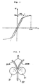
magnetic sheet 12 showing the state wherein flat softmagnetic powder 14 dispersed into alayer 12 of an organic binding agent is oriented so as to be parallel to the surface of the rolled compositemagnetic sheet 12. - Here, "a diamagnetic field" Hd will be explained with reference to Fig. 3.
- A composite magnetic sample is marked for observation of a magnetic particle orienting direction and processed into a cubic shape. Using a VSM (vibrating type magnetometer), M-H curves (magnetization curves) in an orientation direction of the magnetic particles (magnetization easy axis direction) and a direction perpendicular to the orientation direction (magnetization hard axis direction) are derived, respectively, with respect to the cubic sample. Fig. 3 shows the M-H curve. A line (shown by a dotted line in Fig. 3) passing the origin is drawn in parallel to a linear region of the obtained M-H curve, and a magnetic field corresponding to an intersection point between this line and an Ms line (saturation magnetization line) is set to be "a diamagnetic field" Hd.
- A diamagnetic field in "the magnetization easy axis direction" is represented by Hde, while a diamagnetic field in "the magnetization hard axis direction" is represented by Hdd.
- It was confirmed that the composite magnetic sheet produced by the method of Fig. 1 realized a ratio Hdd/Hde of not less than 4.
- As the soft magnetic powder, an Fe-Al-Si alloy (trademark: Sendust) or an Fe-Ni alloy (Permalloy) can be used.
- On the other hand, as the organic binding agent, thermoplastic resin, such as polyester resin, chlorinated polyethylene resin, polyvinyl chloride resin, polyvinyl butyral resin, polyurethane resin, cellulose resin, nitrile-butadiene rubber or stylene-butadiene rubber, or a polymer thereof can be used.
- Some of these organic binding agents may generate heat to be self-fused due to friction upon rolling by the foregoing two rolls. The degree thereof also depends on a rotational speed of the rolls or a gap between the two rolls. For those with small self-fusing degrees or those with no self fusion, heating rolls may be used as the rolls to cause the self fusion.
- It may be arranged that a composite magnetic sheet of a desired thickness is not produced through one rolling process, but the rolling process may be divided and carried out in several times. Specifically, a sheet obtained through one rolling process is further passed under pressure between two rolls with a reduced gap therebetween so that a thin sheet can be obtained. On the contrary, a plurality of, such as two, composite magnetic sheets each produced through one rolling process are passed between two rolls so as to be attached or joined with each other under pressure, and thereby a composite magnetic sheet of a stacked structure with an increased thickness can be obtained. By repeating this method in a plurality of times, a composite magnetic sheet of a given thickness can be obtained. This pressure attaching method is effective for producing a composite magnetic sheet of, particularly. a large thickness.
- On the other hand, in case of using this pressure attaching method, there is a possibility that exfoliation occurs between the mutually joined two sheets.
- Referring to Fig. 4,
unevenness 15 is in advance provided on surfaces, to be mutually attached, ofsheets - Fig. 4 is a diagram for explaining this method.
- Specifically, embossing is applied onto the surfaces of the first and second composite
magnetic sheets magnetic sheets magnetic sheets rolls 21 in the state wherein they are put one over the other with their surfaces, formed with theunevenness 15, being in contact with each other. Through this, both are attached under pressure to obtain a compositemagnetic sheet 22 of a stacked structure. - As described above, by providing in advance the
unevenness 15 on the surfaces of the first and second compositemagnetic sheets magnetic sheets magnetic sheets magnetic sheet 22 can be obtained, wherein the first and second compositemagnetic sheets - Further, by providing the
unevenness 15 on the surfaces of the first and second compositemagnetic sheets magnetic sheets magnetic sheets magnetic sheet 22 excellent in mechanical strength can be obtained. - On the other hand, the
sheet 20A and/or 20B to be mutually attached in pressure is not limited to the sheet produced by the method of Fig. 1, but the sheet of the stacked structure pressure-attached by the method of Fig. 4 can be used. By this, it is evident that a sheet with a further increased thickness can be obtained. - The surfaces of the composite
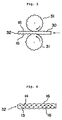
magnetic sheets - Referring to Fig. 5, by passing the composite magnetic sheet obtained in Fig. 1 or 4 (here, collectively represented by 30) between mutually confronting first and second embossing rolls 31 and 31 such that the obverse surface and the reverse surface thereof abut the first and second embossing rolls 31 and 31, respectively, a composite
magnetic sheet 32 formed with unevenness (emboss) 16 on the obverse and reverse surfaces thereof can be obtained. - As shown by a sectional view of Fig. 6, in the thus produced composite
magnetic sheet 32, flat softmagnetic powder 13 is dispersed in alayer 13 of an organic binding agent, and the embossedunevenness 16 is formed on both sides thereof. - Referring to Fig. 7, an electromagnetic wave I incident upon the surface of the composite
magnetic sheet 32 having theunevenness 16 on the obverse and reverse surfaces thereof partly enters the compositemagnetic sheet 32, while the remaining part thereof is scattered on theunevenness 16 so as to enter the compositemagnetic sheet 32 from other portions of the unevenness on the surface. This reduces the reflection level of a reflected wave R. On the other hand, the electromagnetic wave entering the compositemagnetic sheet 32 collides with the soft magnetic powder so as to be absorbed as an absorption loss A. The electromagnetic wave, which has reached an outgoing surface on the reverse side without collision, is scattered due to the unevenness of the surface to return into the compositemagnetic sheet 32 again and subjected to multiple reflection in the interior so as to be absorbed as the absorption loss A in the course thereof. As a result, a portion of the electromagnetic wave entering the composite magnetic sheet and absorbed due to the multiple reflection in the interior is increased. As a result, the transmittance level of a transmitting wave T through the compositemagnetic sheet 32 is lowered, and the reflection level of the reflected wave R is also lowered. - Therefore, by using the composite
magnetic sheet 32, the undesired electromagnetic waves can be effectively absorbed. - Fig. 8 shows a method of producing an electromagnetic
interference suppressing body 42 having two compositemagnetic sheets conductor 50 which are stacked. - First, two composite magnetic bodies with a desired thickness is prepared according to the method of Fig. 1 or 4. On the other hand, as the
conductive sheet 50 having a plurality of holes, an Ni-plated mesh (net) textile, for example, is prepared. - Then, in the state wherein the
conductive sheet 50 is sandwiched between the two compositemagnetic sheets rolls 41 so as to be attached in pressure with each other. Through this, the sheet electromagneticinterference suppressing body 42 having a conductor layer (50) as a center layer and composite magnetic layers (40A and 40B), being magnetic loss layers, as surface layers can be easily obtained. - Since the
conductive sheet 50 has the plurality of holes in the sheet electromagneticinterference suppressing body 42, mutual attaching strengths among the first compositemagnetic sheet 40A, theconductive sheet 50 and the second compositemagnetic sheet 40B are increased so that they are mechanically reluctant to exfoliate from each other. Accordingly, the sheet electromagnetic interference suppressing body excellent in mechanical strength can be obtained. - The
conductive sheet 50 is impregnated with, for example, an adhesive such as a bond for vinyl. This also increases the mutual attaching strengths among the first compositemagnetic sheet 40A, theconductive sheet 50 and the second compositemagnetic sheet 40B. As a result, these sheets are difficult in mechanical exfoliation from each other, and thus the sheet electromagnetic interference suppressing body excellent in mechanical strength can be obtained. In this case, to be concrete, the adhesive such as the bond for vinyl is diluted with a lacquer reducer, applied to the mesh textile as theconductive sheet 50 and dried, so as to impregnate theconductive sheet 50 with the adhesive. - Instead, the Ni-plated mesh textile as the
conductive sheet 50 may be impregnated with a thermosetting organic adhesive excellent in adhesive property relative to the organic binding agent of the first and second compositemagnetic bodies - This sheet electromagnetic interference suppressing body is, for example, cut into an electromagnetic interference suppressing body piece of a desired shape upon use.
- As described above, according to the present invention, the atomized mixture of the soft magnetic powder and the organic binding agent is rolled by the mutually confronting two rolls so that the mass-producible composite magnetic sheet excellent in electromagnetic wave absorption capability can be provided.
- Further, since the given thickness can be achieved by reducing or increasing the thickness by repeating the rolling, the composite magnetic sheet having a desired electromagnetic wave absorption capability can be obtained.
- Further, by providing the unevenness on the surface of the composite magnetic sheet, there can be provided the composite magnetic sheet excellent in electromagnetic wave absorption capability and with reduced reflection and permeation of electromagnetic waves.
- Further, according to the present invention, there can be provided the highly effective electromagnetic interference suppressing sheet excellent in blocking and absorbing the electromagnetic waves, which is formed by rolling and attaching under pressure the foregoing composite magnetic sheets and the mesh metal layer.
Claims (10)
- A method of producing a composite magnetic sheet, which comprises:characterized by a provision of a further step of forming unevenness (16) on both of obverse and reverse surfaces of said composite magnetic sheet (12, 22, 30) for suppressing permeation of an electromagnetic wave to form a composite magnetic sheet (32) with uneven outer surfaces, wherein said unevenness is preferably formed by applying embossing to said obverse and reverse surfaces and wherein preferably said embossing is carried out by confronting first and second embossing rolls (31) such that its obverse and reverse surfaces abut said first and second embossing rolls, respectively.a step of preparing an atomized mixture (10) of soft magnetic powder (13, 14) and an organic binding agent; anda step of rolling said atomized mixture by mutually confronting two rolls (11) to obtain said composite magnetic sheet (12, 22, 30),
- The method of producing the composite magnetic sheet of claim 1, wherein the composite magnetic sheet obtained through the rolling by said two rolls, when formed into a cube, provides a ratio Hdd/Hde, of not less than 4, between a diamagnetic field Hdd in a magnetization hard axis direction and a diamagnetic field Hde in a magnetization easy axis direction.
- The method of producing the composite magnetic sheet of claim 1 or 2, wherein said organic binding agent is fused upon said rolling by the two rolls (11) so that sheeting is realized and wherein said organic binding agent is preferably a self-fusion material and is fused by friction upon said rolling and/or wherein said two rolls preferably are heating rolls, and said organic binding agent is heated and fused upon the rolling by said rolls.
- The method of procuring the composite magnetic sheet as recited in any of claims 1 to 3, wherein said soft magnetic powder (13, 14) is formed of flat particles, and surfaces of the flat particles are oriented in a rolling direction upon said rolling and/or wherein preferably said soft magnetic powder has particle diameters smaller than a desired thickness of the composite magnetic sheet to be produced and/or wherein preferably said rolling step is a step of rolling said atomized mixture (10) by the two rolls confronting with a distance therebetween substantially equal to said thickness so as to obtain said composite magnetic sheet (12, 22, 30).
- The method of producing the composite magnetic sheet as recited in any of claims 1 to 4, which has, subsequent to said composite magnetic sheet between rolling rolls (11) so as to reduce its thickness to a desired thickness.
- The method of producing the composite magnetic sheet as recited in any of claims 1 to 5, which has a stacking step of attaching under pressure a plurality of the overlapped composite magnetic sheets (20A, 20B) obtained by said rolling step so as to obtain the composite magnetic sheet (22) of a desired thickness, and which preferably further comprises:an unevenness forming step of forming unevenness (15) on respective surfaces of said plurality of composite magnetic sheets; anda pressure-attaching step of attaching under pressure said plurality of composite magnetic sheets by the mutually confronting two rolls (21) in the state that they are put one over the other with said surfaces, formed with the unevenness, being in contact with each other and wherein preferably said unevenness forming step applies embossing to the respective surfaces of said plurality of composite magnetic sheets.
- A method of producing an electromagnetic interference suppressing body characterized in that a conductive sheet (50) having a plurality of holes is sandwiched between two composite magnetic sheets (40A, 40B) produced in the method of producing the composite magnetic sheet as recited in any of claims 1 to 6, and these sheets are attached in pressure by mutually confronting two rolls (41) to obtain a stacked sheet as the electromagnetic interference suppressing body (42).
- The method of producing the electromagnetic interference suppressing body as recited in claim 7, wherein said conductive sheet (50) having the plurality of holes is a mesh conductive sheet.
- The method of producing the electromagnetic interference suppressing body as recited in claim 7 or 8, wherein said conductive sheet (50) is impregnated with an adhesive.
- The method of producing the electromagnetic interference suppressing body as recited in claim 9, wherein said adhesive is an adhesive excellent in adhesive property relative to said organic binding agent.
Applications Claiming Priority (16)
| Application Number | Priority Date | Filing Date | Title |
|---|---|---|---|
| JP233327/96 | 1996-09-03 | ||
| JP23332796 | 1996-09-03 | ||
| JP23332796A JPH1079595A (en) | 1996-09-03 | 1996-09-03 | Method for producing electromagnetic interference suppressor |
| JP237995/96 | 1996-09-09 | ||
| JP237996/96 | 1996-09-09 | ||
| JP23799696A JPH1080930A (en) | 1996-09-09 | 1996-09-09 | Method for producing composite magnetic sheet |
| JP23799596 | 1996-09-09 | ||
| JP23799596A JP3722392B2 (en) | 1996-09-09 | 1996-09-09 | Method for producing composite magnetic material |
| JP23799696 | 1996-09-09 | ||
| JP24371096A JP3807791B2 (en) | 1996-09-13 | 1996-09-13 | Electromagnetic interference suppressor and method for producing composite magnetic material used therefor |
| JP243710/96 | 1996-09-13 | ||
| JP24371096 | 1996-09-13 | ||
| JP8258310A JPH10107541A (en) | 1996-09-30 | 1996-09-30 | Composite magnetic material, method for producing the same, and electromagnetic interference suppressor |
| JP25831096 | 1996-09-30 | ||
| JP258310/96 | 1996-09-30 | ||
| PCT/JP1997/003068 WO1998009788A1 (en) | 1996-09-03 | 1997-09-02 | Method of manufacturing composite magnetic sheet |
Publications (3)
| Publication Number | Publication Date |
|---|---|
| EP0873839A1 EP0873839A1 (en) | 1998-10-28 |
| EP0873839A4 EP0873839A4 (en) | 1999-01-13 |
| EP0873839B1 true EP0873839B1 (en) | 2004-11-24 |
Family
ID=27529911
Family Applications (1)
| Application Number | Title | Priority Date | Filing Date |
|---|---|---|---|
| EP97937877A Expired - Lifetime EP0873839B1 (en) | 1996-09-03 | 1997-09-02 | Method of manufacturing composite magnetic sheet |
Country Status (6)
| Country | Link |
|---|---|
| US (2) | US6187120B1 (en) |
| EP (1) | EP0873839B1 (en) |
| KR (2) | KR100475768B1 (en) |
| CN (1) | CN1082871C (en) |
| DE (1) | DE69731727T2 (en) |
| WO (1) | WO1998009788A1 (en) |
Cited By (2)
| Publication number | Priority date | Publication date | Assignee | Title |
|---|---|---|---|---|
| US8241752B2 (en) | 1998-11-02 | 2012-08-14 | 3M Innovative Properties Company | Transparent conductive articles and methods of making same |
| US8350451B2 (en) | 2008-06-05 | 2013-01-08 | 3M Innovative Properties Company | Ultrathin transparent EMI shielding film comprising a polymer basecoat and crosslinked polymer transparent dielectric layer |
Families Citing this family (24)
| Publication number | Priority date | Publication date | Assignee | Title |
|---|---|---|---|---|
| DE69731727T2 (en) * | 1996-09-03 | 2005-11-10 | Nec Tokin Corp., Sendai | METHOD FOR MANUFACTURING MAGNETIC COMPOSITE FILM |
| WO2001024205A1 (en) * | 1999-09-28 | 2001-04-05 | Tokin Corporation | Composite magnetic sheet and method of producing the same |
| CN1288753C (en) * | 2000-04-04 | 2006-12-06 | Nec东金株式会社 | Electromagnetic noise suppressor, semiconductor device using same, and manufacturing method thereof |
| RU2195035C1 (en) * | 2001-08-01 | 2002-12-20 | Акционерное общество закрытого типа "Лэзертач" | Device for manufacturing rubber ferrite sheets; magnetic powder and adhesive batcher |
| RU2193250C1 (en) * | 2001-08-01 | 2002-11-20 | Акционерное общество закрытого типа "Лэзертач" | Method for manufacture of magnetoplastics |
| US7215473B2 (en) | 2002-08-17 | 2007-05-08 | 3M Innovative Properties Company | Enhanced heat mirror films |
| US6929864B2 (en) | 2002-08-17 | 2005-08-16 | 3M Innovative Properties Company | Extensible, visible light-transmissive and infrared-reflective film and methods of making and using the film |
| US6818291B2 (en) | 2002-08-17 | 2004-11-16 | 3M Innovative Properties Company | Durable transparent EMI shielding film |
| US6933051B2 (en) | 2002-08-17 | 2005-08-23 | 3M Innovative Properties Company | Flexible electrically conductive film |
| KR100463593B1 (en) * | 2002-11-27 | 2004-12-29 | 주식회사 메틱스 | Electro magnetic absorption sheet and manufacturing method of electro magnetic absorption sheet |
| US7208115B2 (en) * | 2003-03-31 | 2007-04-24 | Lockheed Martin Corporation | Method of fabricating a polymer matrix composite electromagnetic shielding structure |
| KR100673531B1 (en) * | 2005-01-31 | 2007-01-24 | 주식회사 에이엠아이 씨 | Thin electromagnetic shielding tape, electromagnetic shielding structure using the same and manufacturing method thereof |
| FR2889353A1 (en) * | 2005-07-26 | 2007-02-02 | Chiang Chen Liang Fan | Soft magnet structure for making e.g. magnetic clip, has plane blank of soft magnet embossed with tissue of densely arranged stripes, where stripes extend in same direction and are arranged on surface of blank |
| BRPI0721299B1 (en) | 2006-12-28 | 2018-07-24 | 3M Innovative Properties Company. | METHOD FOR FORMATION OF A CONDUCTIVE FILM ON A FLEXIBLE POLYMER HOLDER, CONDUCTORY FILM AND METHOD FOR THE MANUFACTURE OF A VITRIFICATION ARTICLE |
| CN101056530B (en) * | 2007-04-30 | 2011-06-08 | 电子科技大学 | Preparing method of high temperature resistant electromagnetic wave absorbent material film |
| WO2008150117A2 (en) * | 2007-06-05 | 2008-12-11 | Advanced Materials & Integration Co., Ltd | Manufacturing method of emi shielding fabric sheet with hot-melt adhesive layer |
| KR100917138B1 (en) * | 2007-10-04 | 2009-09-15 | 주식회사 아원 | Method for manufacturing electromagnetic wave absorber sheet for distance recognition of wireless recognition antenna |
| US8440128B2 (en) | 2007-11-26 | 2013-05-14 | Thomas G. Love | Flexible magnetic sheet systems |
| JP5324105B2 (en) * | 2008-01-29 | 2013-10-23 | スリーエム イノベイティブ プロパティズ カンパニー | Electromagnetic interference suppression sheet comprising a pressure sensitive adhesive layer having a structured surface |
| US8301873B2 (en) * | 2009-12-01 | 2012-10-30 | Getac Technology Corporation | Method and computer system for thermal throttling protection |
| JP2011129798A (en) * | 2009-12-21 | 2011-06-30 | Mitsumi Electric Co Ltd | Magnetic material for high frequency application, high-frequency device, and magnetic grain |
| GB201110233D0 (en) * | 2011-06-16 | 2011-08-03 | Williams Hybrid Power Ltd | Magnetically loaded composite rotors and tapes used in the production thereof |
| CN102529123B (en) * | 2011-11-25 | 2014-08-06 | 南昌大学 | Sheet molding compound (SMC) process preparation method of electromagnetic wave absorbing composite material |
| CN109041556A (en) * | 2018-07-16 | 2018-12-18 | 苏州微磁新材料有限公司 | Absorbing material and its preparation method and application |
Family Cites Families (24)
| Publication number | Priority date | Publication date | Assignee | Title |
|---|---|---|---|---|
| US4277298A (en) | 1973-06-25 | 1981-07-07 | The Cly-Del Manufacturing Company | Method of making a hollow article |
| DE2812445C2 (en) * | 1978-03-22 | 1983-10-13 | Robert Bosch Gmbh, 7000 Stuttgart | Process for the production of molding compounds with soft magnetic properties |
| JPS6044807B2 (en) | 1980-02-06 | 1985-10-05 | 松下電器産業株式会社 | Manufacturing method for magnetic plastic molded bodies |
| JPS57109130A (en) * | 1980-12-25 | 1982-07-07 | Tokyo Jiki Insatsu Kk | Plastic magnetic shield plate |
| DE3473408D1 (en) * | 1983-07-14 | 1988-09-22 | Horst Baermann | Flexible magnetic sheet |
| JPH0746791B2 (en) * | 1985-07-17 | 1995-05-17 | 日本電信電話株式会社 | Howling suppression circuit |
| JPS6232587A (en) * | 1985-08-06 | 1987-02-12 | Nec Corp | Character recognizing system |
| JPS6334730A (en) * | 1986-07-29 | 1988-02-15 | Canon Inc | Production of magnetic recording medium |
| DE3876529T2 (en) | 1987-07-31 | 1993-06-24 | Tdk Corp | MAGNETIC SOFT IRON POWDER FOR SHAPING MAGNETIC SHIELDING, CONNECTION AND METHOD FOR PRODUCING IT. |
| JP2668982B2 (en) | 1988-09-19 | 1997-10-27 | 凸版印刷株式会社 | Aseptic filling and packaging machine |
| EP0406449A4 (en) * | 1989-01-19 | 1991-12-04 | Konica Corporation | Magnetic recording medium |
| JP3032808B2 (en) * | 1989-09-29 | 2000-04-17 | コニカ株式会社 | Manufacturing method of magnetic recording medium |
| JPH0461023A (en) * | 1990-06-29 | 1992-02-27 | Konica Corp | magnetic recording medium |
| JPH06102367B2 (en) * | 1992-10-22 | 1994-12-14 | 野頼 ▲のぶ▼昌 | Interior sheet material mixed with functional powder and manufacturing method |
| JPH06232587A (en) * | 1993-01-28 | 1994-08-19 | Shin Etsu Polymer Co Ltd | Method for manufacturing electromagnetic wave shield molding |
| JPH0738274A (en) * | 1993-07-16 | 1995-02-07 | Ii & C Eng Kk | Method of manufacturing radio wave absorber |
| JP3401650B2 (en) * | 1994-01-20 | 2003-04-28 | エヌイーシートーキン株式会社 | Electromagnetic interference suppressor |
| FI117224B (en) * | 1994-01-20 | 2006-07-31 | Nec Tokin Corp | Electromagnetic piece for removing interference, as well as electronic device and hybrid microcircuit element in which it is used |
| JPH088582A (en) * | 1994-06-17 | 1996-01-12 | Daifuku Seishi Kk | Conductive sheet and resin molded product having the conductive sheet |
| US5770304A (en) * | 1994-07-11 | 1998-06-23 | Nippon Paint Co., Ltd. | Wide bandwidth electromagnetic wave absorbing material |
| JPH0883994A (en) * | 1994-07-11 | 1996-03-26 | Nippon Paint Co Ltd | Broadband electromagnetic wave absorbing material |
| JPH0993034A (en) * | 1995-09-22 | 1997-04-04 | Tokin Corp | Composite magnetic material, method for producing the same, and electromagnetic interference suppressor |
| DE69731727T2 (en) * | 1996-09-03 | 2005-11-10 | Nec Tokin Corp., Sendai | METHOD FOR MANUFACTURING MAGNETIC COMPOSITE FILM |
| US5984856A (en) * | 1998-06-29 | 1999-11-16 | Magnum Magnetics | Spiral field magnetic product |
-
1997
- 1997-09-02 DE DE69731727T patent/DE69731727T2/en not_active Expired - Lifetime
- 1997-09-02 EP EP97937877A patent/EP0873839B1/en not_active Expired - Lifetime
- 1997-09-02 KR KR19987003164A patent/KR100475768B1/en not_active Expired - Fee Related
- 1997-09-02 WO PCT/JP1997/003068 patent/WO1998009788A1/en not_active Ceased
- 1997-09-02 CN CN97191127A patent/CN1082871C/en not_active Expired - Fee Related
- 1997-09-02 US US09/068,144 patent/US6187120B1/en not_active Expired - Lifetime
- 1997-09-02 KR KR1019980703164A patent/KR20000064304A/en active Granted
-
2000
- 2000-06-16 US US09/613,330 patent/US6740289B1/en not_active Expired - Fee Related
Cited By (2)
| Publication number | Priority date | Publication date | Assignee | Title |
|---|---|---|---|---|
| US8241752B2 (en) | 1998-11-02 | 2012-08-14 | 3M Innovative Properties Company | Transparent conductive articles and methods of making same |
| US8350451B2 (en) | 2008-06-05 | 2013-01-08 | 3M Innovative Properties Company | Ultrathin transparent EMI shielding film comprising a polymer basecoat and crosslinked polymer transparent dielectric layer |
Also Published As
| Publication number | Publication date |
|---|---|
| KR20000064304A (en) | 2000-11-06 |
| WO1998009788A1 (en) | 1998-03-12 |
| DE69731727T2 (en) | 2005-11-10 |
| EP0873839A1 (en) | 1998-10-28 |
| US6187120B1 (en) | 2001-02-13 |
| EP0873839A4 (en) | 1999-01-13 |
| CN1082871C (en) | 2002-04-17 |
| DE69731727D1 (en) | 2004-12-30 |
| US6740289B1 (en) | 2004-05-25 |
| CN1199361A (en) | 1998-11-18 |
| KR100475768B1 (en) | 2005-05-16 |
Similar Documents
| Publication | Publication Date | Title |
|---|---|---|
| US6740289B1 (en) | Method of producing a composite magnetic sheet | |
| KR100627114B1 (en) | Composite magnetic body, electromagnetic wave absorbing sheet, manufacturing method of sheet-like article, and manufacturing method of electromagnetic wave absorbing sheet | |
| CN113725626B (en) | Double-layer resonance coupling wave absorber | |
| US20180366823A1 (en) | Antenna | |
| KR100523051B1 (en) | Composite magnetic sheet and method of producing the same | |
| KR101755607B1 (en) | Magnetic shielding materials of wireless power transfer apparatus, manufacturing method of the same | |
| JPH0974297A (en) | Radio wave absorber | |
| Violi et al. | Design of passive and wideband radar absorbing materials comprising resistive frequency selective surfaces | |
| KR101825192B1 (en) | Electromagnetic wave absorbing structures including metal-coated fabric layer and methods of manufacturing the same | |
| JP2920178B2 (en) | Radio wave absorber | |
| JPH06209181A (en) | Radio wave absorber | |
| JP3825210B2 (en) | Electromagnetic interference suppressor and method for manufacturing the same | |
| JPS58188193A (en) | radio wave absorber | |
| JP3807791B2 (en) | Electromagnetic interference suppressor and method for producing composite magnetic material used therefor | |
| JPH1079595A (en) | Method for producing electromagnetic interference suppressor | |
| JPH05291784A (en) | Radio wave absorber | |
| JP6479643B2 (en) | Radio wave absorber and manufacturing method thereof | |
| JPH05335779A (en) | Electric wave absorber | |
| JPH02272799A (en) | Manufacture of electromagnetic wave shielding sheet material | |
| JP2001118711A (en) | Laminated magnetic wood | |
| JPH0638476Y2 (en) | Radio wave absorption wall | |
| JPH05335778A (en) | Installation of electric wave absorber | |
| JPH0212896A (en) | Radio wave absorber | |
| KR20170065353A (en) | Manufacturing method of magnetic materials for wireless charging module, and magnetic materials, and wireless charging module using the same | |
| JPS6314497A (en) | Electric wave absorbing and shielding material |
Legal Events
| Date | Code | Title | Description |
|---|---|---|---|
| PUAI | Public reference made under article 153(3) epc to a published international application that has entered the european phase |
Free format text: ORIGINAL CODE: 0009012 |
|
| 17P | Request for examination filed |
Effective date: 19980430 |
|
| AK | Designated contracting states |
Kind code of ref document: A2 Designated state(s): DE FR GB IT |
|
| A4 | Supplementary search report drawn up and despatched |
Effective date: 19981130 |
|
| AK | Designated contracting states |
Kind code of ref document: A4 Designated state(s): DE FR GB IT |
|
| 17Q | First examination report despatched |
Effective date: 20010607 |
|
| RAP1 | Party data changed (applicant data changed or rights of an application transferred) |
Owner name: NEC TOKIN CORPORATION |
|
| GRAP | Despatch of communication of intention to grant a patent |
Free format text: ORIGINAL CODE: EPIDOSNIGR1 |
|
| GRAS | Grant fee paid |
Free format text: ORIGINAL CODE: EPIDOSNIGR3 |
|
| GRAA | (expected) grant |
Free format text: ORIGINAL CODE: 0009210 |
|
| AK | Designated contracting states |
Kind code of ref document: B1 Designated state(s): DE FR GB IT |
|
| REG | Reference to a national code |
Ref country code: GB Ref legal event code: FG4D |
|
| REF | Corresponds to: |
Ref document number: 69731727 Country of ref document: DE Date of ref document: 20041230 Kind code of ref document: P |
|
| PG25 | Lapsed in a contracting state [announced via postgrant information from national office to epo] |
Ref country code: IT Free format text: LAPSE BECAUSE OF NON-PAYMENT OF DUE FEES Effective date: 20050902 |
|
| PLBE | No opposition filed within time limit |
Free format text: ORIGINAL CODE: 0009261 |
|
| STAA | Information on the status of an ep patent application or granted ep patent |
Free format text: STATUS: NO OPPOSITION FILED WITHIN TIME LIMIT |
|
| ET | Fr: translation filed | ||
| 26N | No opposition filed |
Effective date: 20050825 |
|
| PGFP | Annual fee paid to national office [announced via postgrant information from national office to epo] |
Ref country code: GB Payment date: 20090902 Year of fee payment: 13 |
|
| PGFP | Annual fee paid to national office [announced via postgrant information from national office to epo] |
Ref country code: FR Payment date: 20100921 Year of fee payment: 14 |
|
| PGFP | Annual fee paid to national office [announced via postgrant information from national office to epo] |
Ref country code: DE Payment date: 20100825 Year of fee payment: 14 |
|
| GBPC | Gb: european patent ceased through non-payment of renewal fee |
Effective date: 20100902 |
|
| PG25 | Lapsed in a contracting state [announced via postgrant information from national office to epo] |
Ref country code: GB Free format text: LAPSE BECAUSE OF NON-PAYMENT OF DUE FEES Effective date: 20100902 |
|
| REG | Reference to a national code |
Ref country code: FR Ref legal event code: ST Effective date: 20120531 |
|
| PG25 | Lapsed in a contracting state [announced via postgrant information from national office to epo] |
Ref country code: DE Free format text: LAPSE BECAUSE OF NON-PAYMENT OF DUE FEES Effective date: 20120403 |
|
| REG | Reference to a national code |
Ref country code: DE Ref legal event code: R119 Ref document number: 69731727 Country of ref document: DE Effective date: 20120403 |
|
| PG25 | Lapsed in a contracting state [announced via postgrant information from national office to epo] |
Ref country code: FR Free format text: LAPSE BECAUSE OF NON-PAYMENT OF DUE FEES Effective date: 20110930 |