EP0873094B1 - Obturator zum kalibrieren von künstlichen aortenklappen - Google Patents
Obturator zum kalibrieren von künstlichen aortenklappen Download PDFInfo
- Publication number
- EP0873094B1 EP0873094B1 EP97905563A EP97905563A EP0873094B1 EP 0873094 B1 EP0873094 B1 EP 0873094B1 EP 97905563 A EP97905563 A EP 97905563A EP 97905563 A EP97905563 A EP 97905563A EP 0873094 B1 EP0873094 B1 EP 0873094B1
- Authority
- EP
- European Patent Office
- Prior art keywords
- obturator
- cylindrical
- sizing
- flange
- aortic
- Prior art date
- Legal status (The legal status is an assumption and is not a legal conclusion. Google has not performed a legal analysis and makes no representation as to the accuracy of the status listed.)
- Expired - Lifetime
Links
Images

Classifications
-
- A—HUMAN NECESSITIES
- A61—MEDICAL OR VETERINARY SCIENCE; HYGIENE
- A61F—FILTERS IMPLANTABLE INTO BLOOD VESSELS; PROSTHESES; DEVICES PROVIDING PATENCY TO, OR PREVENTING COLLAPSING OF, TUBULAR STRUCTURES OF THE BODY, e.g. STENTS; ORTHOPAEDIC, NURSING OR CONTRACEPTIVE DEVICES; FOMENTATION; TREATMENT OR PROTECTION OF EYES OR EARS; BANDAGES, DRESSINGS OR ABSORBENT PADS; FIRST-AID KITS
- A61F2/00—Filters implantable into blood vessels; Prostheses, i.e. artificial substitutes or replacements for parts of the body; Appliances for connecting them with the body; Devices providing patency to, or preventing collapsing of, tubular structures of the body, e.g. stents
- A61F2/02—Prostheses implantable into the body
- A61F2/24—Heart valves ; Vascular valves, e.g. venous valves; Heart implants, e.g. passive devices for improving the function of the native valve or the heart muscle; Transmyocardial revascularisation [TMR] devices; Valves implantable in the body
- A61F2/2496—Devices for determining the dimensions of the prosthetic valve to be implanted, e.g. templates, sizers
-
- A—HUMAN NECESSITIES
- A61—MEDICAL OR VETERINARY SCIENCE; HYGIENE
- A61B—DIAGNOSIS; SURGERY; IDENTIFICATION
- A61B5/00—Measuring for diagnostic purposes; Identification of persons
- A61B5/103—Detecting, measuring or recording devices for testing the shape, pattern, colour, size or movement of the body or parts thereof, for diagnostic purposes
- A61B5/107—Measuring physical dimensions, e.g. size of the entire body or parts thereof
- A61B5/1076—Measuring physical dimensions, e.g. size of the entire body or parts thereof for measuring dimensions inside body cavities, e.g. using catheters
-
- A—HUMAN NECESSITIES
- A61—MEDICAL OR VETERINARY SCIENCE; HYGIENE
- A61F—FILTERS IMPLANTABLE INTO BLOOD VESSELS; PROSTHESES; DEVICES PROVIDING PATENCY TO, OR PREVENTING COLLAPSING OF, TUBULAR STRUCTURES OF THE BODY, e.g. STENTS; ORTHOPAEDIC, NURSING OR CONTRACEPTIVE DEVICES; FOMENTATION; TREATMENT OR PROTECTION OF EYES OR EARS; BANDAGES, DRESSINGS OR ABSORBENT PADS; FIRST-AID KITS
- A61F2/00—Filters implantable into blood vessels; Prostheses, i.e. artificial substitutes or replacements for parts of the body; Appliances for connecting them with the body; Devices providing patency to, or preventing collapsing of, tubular structures of the body, e.g. stents
- A61F2/02—Prostheses implantable into the body
- A61F2/24—Heart valves ; Vascular valves, e.g. venous valves; Heart implants, e.g. passive devices for improving the function of the native valve or the heart muscle; Transmyocardial revascularisation [TMR] devices; Valves implantable in the body
- A61F2/2427—Devices for manipulating or deploying heart valves during implantation
-
- A—HUMAN NECESSITIES
- A61—MEDICAL OR VETERINARY SCIENCE; HYGIENE
- A61B—DIAGNOSIS; SURGERY; IDENTIFICATION
- A61B90/00—Instruments, implements or accessories specially adapted for surgery or diagnosis and not covered by any of the groups A61B1/00 - A61B50/00, e.g. for luxation treatment or for protecting wound edges
- A61B90/06—Measuring instruments not otherwise provided for
Definitions
- the present invention pertains generally to medical devices and more particularly to an obturator apparatus insertable into an aortic valve annulus of a human heart following performance of a valvulotomy for the purpose of determining the correct size of a prosthetic valve to be surgically implanted therein.
- Surgical valvulotomy and prosthetic valve replacement has been performed in human beings for many years. Most frequently, the procedures are utilized to replace mitral or aortic valves in patients who suffer from valvular heart disease.
- Aortic valvular heart disease may be caused by a number of factors, including congenital deformations, infections, degenerative calcification, and certain rheumatological heart disorders.
- Surgical replacement of the aortic valve is typically performed under general anesthesia, with full cardiopulmonary bypass.
- the leaflets of the endogenous aortic valve are removed along with any calcified surrounding tissue. This results in the formation of an annular opening at the site of the endogenous aortic valve.
- a mechanical or bioprosthetic aortic valve is then selected and sutured into the annular valve opening, as a prosthetic replacement for the surgically-removed endogenous valve.
- Examples of mechanical prosthetic aortic valves which have heretofore been utilized, include the Starr-EdwardsTM Silastic Ball Valve (Baxter Healthcare Corporation, Edwards CVC Division, 17221 Red Hill Ave., P.O.
- bioprosthetic aortic valves which have heretofore been utilized include the Carpentier-Edwards®, PERIMOUNTTM Pericardial Bioprosthesis (Baxter Healthcare Corporation, Edwards CVS Division, 17221 Red Hill Ave., P.O.
- these prosthetic aortic valves comprise a cylindrical valve body having a blood flow passageway extending longitudinally therethrough, and a suture ring formed annularly thereabout.
- the suture ring comprises suture penetrable material or a series of suture passage apertures, to facilitate anastomosis of the suture ring to the adjacent surgically-prepared aortic annulus.
- the natural aortic root Because of the tricuspid configuration of the endogenous aortic valve, the natural aortic root has a non-planar, multi-curvate configuration.
- some or all of the aortic prosthetic valve of the prior art have utilized suture rings which are of a generally non-planar, multi-curvate configuration.
- any aortic valve placement procedure is dependant on a number of factors, including the correct sizing and placement of the prosthetic aortic valve.
- a sizing obturator to determine the correct size of prosthetic valve for implantation.
- Such sizing obturators typically comprise a series of different-sized cylindrical members which are independently attachable to a handle, and which are insertable into the surgically-prepared valve annulus to determine the actual size of the annular opening.
- Such sizing obturators may be color-coded for size identification.
- Examples of aortic and mitral valve sizing obturators of the prior art include the True-SizeTM Aortic Obturator-Model 1161 and the True-SizeTM Mitral Obturator-Model 1162, Baxter Healthcare Corporation, Edwards CVS Division, 17221 Red Hill Ave., P.O. Box 1150, Santa Ana, California 92711-1150.
- WO/9516410 Another prior art sizing obturator is seen in WO/9516410 from Autogenics of Newbury Park, California.
- This reference which is used as basis for the preamble of claim 1 discloses a cylindrical obturator body having a top end, a bottom end, and an outer surface having a first outer diameter.
- a flange member formed about the body has an upper surface, an under surface, and a second outer diameter larger than the first outer diameter.
- a plurality of differently sized obturators are made available and separately manipulated using a common handle.
- aortic valve sizing obturators of the prior art typically comprise a generally cylindrical obturator body having a flat annular flange extending therearound.
- the flat annular flange is typically advanced into abutment with, but does not actually seat or nest within, the nonplanar, three-peaked anatomy of the natural aortic root, which defines the superior aspect of the aortic annulus.
- a primary object of the present invention is to provide a sizing obturator which has a cylindrical body which may be inserted through the annulus, and a flange member which is configured to be substantially complimentary to the configuration of the superior aspect of the aortic annulus, within which a prosthetic valve is to be subsequently implanted.
- Another object of the present invention is to provide such a sizing obturator whose cylindrical body has, disposed therein, a connector member which is connectable to a handle usable during obturator placement.
- Yet another object of the present invention is to provide the above-defined obturator in a plurality of sizes to thereby accurately reflect aortic annulus size for subsequent prosthetic valve implantation.
- the present invention as defined in claim 1 is an aortic valve sizing obturator apparatus for employment in determining the correct size of an aortic annulus so that a correctly sized prosthetic valve can be chosen for subsequent placement within the annulus.
- the apparatus comprises a cylindrical obturator body having a top end, a bottom end, an outer surface, and a first outer diameter.
- a flange member is formed about the top end of the obturator body and has an upper surface, an under surface, and a second outer diameter which is greater than the first outer diameter of the obturator body.
- the undersurface of the flange member is of a non-planar, multi-curvate (i.e., having more than one curve formed therein) configuration to thereby be complimentary in shape to the superior aspect of the aortic annulus such that the flange may be seated or nested within the supra-annular anatomy three peaked configuration of the aortic root during size determination.
- a handle connector apparatus to which a separate handle can be attached to facilitate insertion and placement of the obturator apparatus during the sizing procedure.
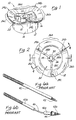
- the preferred aortic valve sizing obturator 10 of the present invention comprises a cylindrical obturator body 12 having an outer surface 14 and an inner surface 16, and a non-planar, multi-curvate annular flange 18 extending outwardly about one end of the cylindrical obturator body 12.
- the non-planar, multi-curvate annular flange 18 has an upper surface 20, and a lower surface 22. (As used in this patent application, the term "multi-curvate" means having more than one curve formed therein.)
- the end of the cylindrical obturator body 12 upon which the non-planar, multi-curvate flange 18 is positioned, and the configuration of the non-planar, multi-curvate flange 18 itself, are characterized by the presence of three equally-spaced-apart blunt peaks 24a, 24b, 24c having three generally arcuate depressions 26a, 26b, 26c extending therebetween, as shown.
- Three (3) radial strut members 28a, 28b, 28c extend inwardly from the inner surface 16 of the cylindrical obturator body 12 at locations which are immediately below each of the discrete blunt peaks 24a, 24b, 24c formed in the non-planar, multi-curvate flange 18.
- a cylindrical inner member 30 is positioned coaxially within the central bore 32 of the cylindrical obturator body 12, and is supported and held in fixed position by the strut members 28a, 28b, 28c.
- a hollow inner bore 34 extends longitudinally through the inner cylindrical member 30, and internal threads 36 are formed on the inner surface of such longitudinal bore 34.
- a single longitudinal axis LA as illustrated in Figure 4 is projectable longitudinally through the cylindrical obturator body 12, such that the obturator body 12 and inner cylindrical member 30 are coaxially disposed about such common longitudinal axis LA.
- Figure 6a-6b show two prior art stainless steel handles which may be utilized in conjunction with the preferred aortic valve sizing obturator shown in Figures 1-5.
- Figure 6a shows a reusable handle comprising an elongate rigid handle member 40 having an externally threaded distal projection 42 extending from the distal end thereof.
- the externally threaded projection 42 is insertable into the upper end of the bore 34 of the inner cylindrical member 30 of the preferred aortic valve sizing obturator 10 of the present invention such that the external threads of projection 42 may be rotatably engaged with the internal threads 36 formed within the bore 34 of the inner cylindrical member 30, thereby attaching the elongate handle member 40 to the aortic valve sizing obturator 10.
- the particular handle shown in Figure 6a has been commercially available as Handle Model 1108, Baxter Healthcare Corporation, Edwards CVC Division, 17221 Red Hill Ave., P.O. Box 11150, Santa Ana, California 92711-1150.
- Figure 6b shows an alternative handle which comprises a segmented rigid handle member 40a having a bendable segment 46 disposed therewithin, and an externally threaded distal projection 42a extending from the distal end thereof.
- a flanged bushing 44 is formed proximal to the externally threaded distal portion 42a, as shown.
- the bendable segment 46 of this handle may be manually bent or preformed by the surgeon to a desired configuration to facilitate insertion and positioning of the aortic valve sizing obturator 10.
- the particular handle shown in Figure 6b has been commercially available as Handle Model 1111, Baxter Healthcare Corporation Edwards CVC Division, 17221 Red Hill Ave., P.O. Box 11150, Santa Ana, California 92711-1150.
- the aortic valve sizing obturator 10 may be formed of any suitable material including rigid, autoclavable thermoplastic material such as polysulfonate.
- the obturators 10 will typically be provided in a kit consisting of a series of different-sized obturators 10, corresponding to the available sizes of the particular prosthetic heart valves for which the obturator 10 is to be employed.
- the following table shows examples of specific component dimensions (in millimeters) of standard, commercially available sizes of the Carpentier-Edwards® PERIMOUNTTM Pericardial Aortic Bioprosthesis referred to hereabove: Mounting Diameter (Annulus) 19 21 23 25 27 29 Internal Diameter (Stent I.D.) 18 20 22 24 26 28 Profile Height 13 14 15 16 17 18 External Sewing Ring Diameter 28 31 33 35 38 40
- the manufacturer will typically provide a kit having a series of different-sized obturators 10, which correspond directly to the available sizes of the Model 2700 Aortic Valvular Prosthesis.
- an obturator 10 having a mounting diameter (i.e., the diameter of the outer surface 14 of the cylindrical obturator body 12) of 19 is found to provide the best fit within the surgically-prepared valve annulus, a Model 2700 prosthetic valve having a mounting diameter of 19 will typically be selected.
- the sizing obturator 10 of the present invention is provided with a non-planar, multi-curvate flange 18, such flange may be directly nested or seated within the surgically-prepared natural valve annulus to provide a direct and precise indication of the correct external sewing ring diameter desired.
- the prosthetic valve in most aortic valve replacement surgeries, is implanted in a supra-annular position wherein the suture ring of the prosthetic valve is positioned superior to the surgically-prepared valve annulus.
- the sizing obturator 10 when it is desired to utilize the typical supra-annular positioning of the prosthetic valve, the sizing obturator 10 will be inserted such that the non-planar, multi-curvate flange 18 is nested or seated in a supra-annular position which is analogous to the intended positioning of the suturing ring of the prosthetic valve.
- the sizing obturator 10 of the present invention will be initially placed such that the non-planar, multi-curvate annular flange 18 is located in the desired intra-annular position.
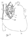
- Figures 7-7a provide a schematic illustration of the typical manner in which the aortic valve sizing obturator 10 of the present invention may be utilized to determine the correct prosthetic valve size to be used for supra-annular implantation in a human heart.
- the major anatomical structures are labeled accordingly to the following legend:
- a handle such as that shown in Figure 6b is initially inserted and engaged into the upper end of the hollow bore 34 of the sizing obturator 10, and the threaded distal projection 42a of the handle is rotatably advanced such that its external threads will rotatably engage the internal threads 36 formed within the bore 34 of the obturator 10.
- the handle of the type shown in Figure 6b is firmly attached to the obturator 10, and extends in a longitudinally coaxial fashion from the upper end of the obturator 10, as shown.
- the diseased or damaged aortic valve leaflets, and all associated structures deemed necessary, are surgically removed.
- the surgeon may also remove any calcium from the valve annulus, to ensure proper seating of the suture ring of the prosthetic valve.
- the aortic valve sizing obturator 10 of the present invention will be inserted such that the cylindrical obturator body 12 passes downwardly through the surgically-prepared valve annulus with little resistance.
- the obturator 10 is then rotatably reoriented and further advanced until the undersurface 22 of the non-planar, multi-curvate flange becomes nested or seated within the non-planar, multi-curvate anatomical structure of the natural aortic root. In this manner, the surgeon may visually verify that the diameter of the cylindrical obturator body 12 and non-planar, multi-curvate annular flange 18 are correct for that particular patient.
- the surgeon may select a prosthetic aortic valve which has a mounting (annulus) diameter and external sewing ring diameter the same as that of the obturator 10 which was found to correctly fit within the patient's aortic valve annulus.
- the obturator 10 and accompanying handle may be extracted and removed, and the selected prosthetic aortic valve may be sutured into place.
- the handle may be rotatably detached and removed from the obturator 10, and both the stainless steel handle and the molded plastic obturator may be autoclaved or otherwise sterilized for subsequent reuse.
Claims (14)
- Obturator-Vorrichtung (10), die eine Aortenklappe auf ein genaues Maß bringt und folgendes aufweist:einen zylinderförmigen Obturator-Körper (12) mit einem oberen Ende, einem Bodenende und eine Außenoberfläche (14), die einen ersten Außendurchmesser hat; undein Flanschteil (18), das um das obere Ende des zylinderförmigen Obturator-Körpers herum ausgebildet ist, wobei das Flanschteil eine obere Oberfläche (20), eine untere Oberfläche (22) und einen zweiten Außendurchmesser hat, welcher größer ist als der erste Außendurchmesser;
dadurch gekennzeichnet,
daß die untere Oberfläche des Flanschteiles (18) eine nicht plane, vielfach gekrümmte Konfiguration hat. - Vorrichtung nach Anspruch 1,
bei der die nicht plane, vielfach gekrümmte Konfiguration der unteren Oberfläche des Flanschteiles folgendes aufweist:drei beabstandete Gipfelstellen (24a, 24b, 24c) mit drei bogenförmigen Senken (26a, 26b, 26c), wobei jede der bogenförmigen Senken sich zwischen benachbarten Gipfelstellen der Gipfelstellen erstreckt. - Vorrichtung nach Anspruch 2,
bei der die Gipfelstellen äquidistant beabstandet sind. - Vorrichtung nach Anspruch 1,
bei der der gesamte ringförmige Flansch eine nicht lineare, vielfach gekrümmte Konfiguration besitzt. - Vorrichtung nach Anspruch 4,
bei der die obere Oberfläche (20) des Flanschteiles (18) an das obere Ende des zylinderförmigen Obturator-Körpers (12) angrenzt und bei der das obere Ende des zylinderförmigen Obturator-Körpers (12) ebenfalls die nicht ebene, vielfach gekrümmte Konfiguration besitzt. - Vorrichtung nach Anspruch 1,
bei der der zylinderförmige Obturator-Körper (12) hohl ist und eine innere zylinderförmige Oberfläche (16) besitzt. - Vorrichtung nach Anspruch 6,
die folgendes aufweist:ein inneres zylinderförmiges Teil (30), welches in Längsrichtung und koaxial innerhalb des zylinderförmigen Obturator-Körpers (12) angeordnet ist, wobei das innere zylinderförmige Teil starr an dem Obturator-Körper (12) befestigt ist und mit einer Handhabungs-Verbindungsvorrichtung verbunden ist, so daß ein getrenntes Handhabungsteil an der Obturator-Vorrichtung anbringbar ist. - Vorrichtung nach Anspruch 7,
bei der die Verbindungsvorrichtung, die in das innere zylinderförmige Teil eingebaut ist, folgendes aufweist: eine hohle Bohrung (34), die sich in Längsrichtung durch wenigstens einen Bereich des inneren zylinderförmigen Teiles erstreckt, und ein Innengewinde (36), das innerhalb der hohlen Bohrung in solcher Weise ausgebildet ist, daß eine mit einem Außengewinde versehene Handhabe durch Drehung damit in Eingriff gebracht werden kann. - Vorrichtung nach Anspruch 7,
bei der das innere zylinderförmige Teil starr an dem Obturator-Körper mit radialen Strebenteilen (28a, 28b, 28c) befestigt ist, die sich von der Innenoberfläche des zylinderförmigen Obturator-Körpers nach innen erstrecken. - Vorrichtung nach Anspruch 9,
bei der die vielfach gekrümmte Konfiguration der unteren Oberfläche des Flansches folgendes aufweist:drei beabstandete Gipfelstellen (24a, 24b, 24c) mit drei bogenförmigen Senken (26a, 26b, 26c), wobei sich jede bogenförmige Senke zwischen benachbarten Gipfelstellen der Gipfelstellen erstreckt, und bei der drei radiale Strebenteile (28a, 28b, 28c) vorgesehen und an der Innenoberfläche des zylinderförmigen Obturator-Körpers an Stellen angebracht sind, die jeweils benachbart zu den beabstandeten Gipfelstellen vorgesehen sind, die in dem vielfach gekrümmten Flansch ausgebildet sind. - Vorrichtung nach Anspruch 1,
bei der der Obturator-Körper und das Flanschteil aus einem autoklavierbaren thermoplastischen Material bestehen. - Ausrüstung zum Bestimmen der Größe einer prothetischen Aorten-Herzklappe, die in einen chirurgisch vorbereiteten Aorten-Ringraum innerhalb eines Säugetier-Herzens zu implantieren ist, wobei die Ausrüstung eine Vielzahl von auf ein genaues Maß bringende Obturatoren nach Anspruch 1 aufweist, wobei wenigstens der erste Durchmesser von einem der auf ein genaues Maß bringenden Obturatoren verschieden ist von dem ersten Durchmesser eines anderen der auf ein genaues Maß bringenden Obturatoren.
- Ausrüstung nach Anspruch 12,
bei der die vielfach gekrümmte Konfiguration der unteren Oberfläche von jedem auf ein genaues Maß bringenden Obturator-Flansch folgendes aufweist:drei im Umfang beabstandete Gipfelstellen mit drei bogenförmigen Senken, wobei sich jede der bogenförmigen Senken zwischen benachbarten Gipfelstellen der Gipfelstellen erstreckt. - Ausrüstung nach Anspruch 13,
die ferner ein längliches Handhabungsteil aufweist, welches abwechselnd an jedem der auf ein genaues Maß bringenden Obturatoren anbringbar ist, um ausgewählte der Obturatoren in den Aorten-Ringraum einzuführen und anschließend zu entfernen.
Applications Claiming Priority (3)
| Application Number | Priority Date | Filing Date | Title |
|---|---|---|---|
| US58381196A | 1996-01-05 | 1996-01-05 | |
| US583811 | 1996-01-05 | ||
| PCT/US1997/000189 WO1997025003A1 (en) | 1996-01-05 | 1997-01-02 | Sizing obturator for prosthetic aortic valves |
Publications (2)
| Publication Number | Publication Date |
|---|---|
| EP0873094A1 EP0873094A1 (de) | 1998-10-28 |
| EP0873094B1 true EP0873094B1 (de) | 1999-06-30 |
Family
ID=24334652
Family Applications (1)
| Application Number | Title | Priority Date | Filing Date |
|---|---|---|---|
| EP97905563A Expired - Lifetime EP0873094B1 (de) | 1996-01-05 | 1997-01-02 | Obturator zum kalibrieren von künstlichen aortenklappen |
Country Status (6)
| Country | Link |
|---|---|
| US (1) | US5814096A (de) |
| EP (1) | EP0873094B1 (de) |
| JP (1) | JP3822908B2 (de) |
| AU (1) | AU2241497A (de) |
| DE (1) | DE69700302T2 (de) |
| WO (1) | WO1997025003A1 (de) |
Families Citing this family (44)
| Publication number | Priority date | Publication date | Assignee | Title |
|---|---|---|---|---|
| US6019739A (en) * | 1998-06-18 | 2000-02-01 | Baxter International Inc. | Minimally invasive valve annulus sizer |
| AU771852B2 (en) | 1999-01-26 | 2004-04-01 | Edwards Lifesciences Corporation | Anatomical orifice sizers and methods of orifice sizing |
| DE60035495T2 (de) * | 1999-04-28 | 2008-03-20 | St. Jude Medical, Inc., St. Paul | Aortenherzklappenprothesenmess- und -markierungsvorrichtung |
| US6610071B1 (en) | 1999-07-26 | 2003-08-26 | Beth Israel Deaconess Medical Center | Suture system |
| US6350281B1 (en) * | 1999-09-14 | 2002-02-26 | Edwards Lifesciences Corp. | Methods and apparatus for measuring valve annuluses during heart valve-replacement surgery |
| US6678962B1 (en) * | 1999-11-17 | 2004-01-20 | Cardiomend Llc | Device and method for assessing the geometry of a heart valve |
| US6598307B2 (en) * | 1999-11-17 | 2003-07-29 | Jack W. Love | Device and method for assessing the geometry of a heart valve |
| US6719785B2 (en) | 2001-05-17 | 2004-04-13 | St. Jude Medical, Inc. | Aortic heart valve prosthesis implantation tool |
| US7510573B2 (en) * | 2003-03-25 | 2009-03-31 | Shlomo Gabbay | Sizing apparatus |
| US7258698B2 (en) * | 2003-10-17 | 2007-08-21 | Medtronic, Inc. | Prosthetic heart valve sizer assembly with flexible sizer body |
| ITTO20040135A1 (it) | 2004-03-03 | 2004-06-03 | Sorin Biomedica Cardio Spa | Protesi valvolare cardiaca |
| ITTO20050074A1 (it) | 2005-02-10 | 2006-08-11 | Sorin Biomedica Cardio Srl | Protesi valvola cardiaca |
| US20080262603A1 (en) * | 2007-04-23 | 2008-10-23 | Sorin Biomedica Cardio | Prosthetic heart valve holder |
| US8006535B2 (en) | 2007-07-12 | 2011-08-30 | Sorin Biomedica Cardio S.R.L. | Expandable prosthetic valve crimping device |
| GB0716403D0 (en) * | 2007-08-22 | 2007-10-03 | Benoist Girard Sas | Trial prosthetic neck component |
| US9848981B2 (en) | 2007-10-12 | 2017-12-26 | Mayo Foundation For Medical Education And Research | Expandable valve prosthesis with sealing mechanism |
| US20090192603A1 (en) * | 2008-01-25 | 2009-07-30 | Medtronic, Inc. | Adjustable Sizer Devices for Minimally Invasive Cardiac Surgery |
| US20090192600A1 (en) * | 2008-01-25 | 2009-07-30 | Ryan Timothy R | Sizing device having two sizers and methods of use |
| US8317696B2 (en) * | 2008-12-15 | 2012-11-27 | Coroneo, Inc. | Surgical tool for measurement of valve annulus and cusp geometry |
| ES2551694T3 (es) | 2008-12-23 | 2015-11-23 | Sorin Group Italia S.R.L. | Válvula protésica expansible dotada de apéndices de anclaje |
| US8715207B2 (en) | 2009-03-19 | 2014-05-06 | Sorin Group Italia S.R.L. | Universal valve annulus sizing device |
| ES2543460T3 (es) * | 2009-03-26 | 2015-08-19 | Sorin Group Usa, Inc. | Dispositivos de dimensionamiento de anuloplastia para intervenciones mínimamente invasivas |
| US20110022165A1 (en) | 2009-07-23 | 2011-01-27 | Edwards Lifesciences Corporation | Introducer for prosthetic heart valve |
| US20110251598A1 (en) | 2010-04-13 | 2011-10-13 | Shigeyuki Ozaki | Instrument of patterning cusp for cardiac valve reconstruction and component thereof |
| IT1400327B1 (it) | 2010-05-21 | 2013-05-24 | Sorin Biomedica Cardio Srl | Dispositivo di supporto per protesi valvolari e corrispondente corredo. |
| ES2641902T3 (es) | 2011-02-14 | 2017-11-14 | Sorin Group Italia S.R.L. | Dispositivo de anclaje sin sutura para prótesis valvulares cardiacas |
| EP2486894B1 (de) | 2011-02-14 | 2021-06-09 | Sorin Group Italia S.r.l. | Vorrichtung zur nahtlosen Verankerung von Herzklappenprothesen |
| US9889009B2 (en) | 2011-10-26 | 2018-02-13 | Nikola Dobrilovic | Heart valve sizing ring and method |
| US9839516B2 (en) | 2012-04-27 | 2017-12-12 | Nikola Dobrilovic | Prosthetic device for heart valve reinforcement and remodeling procedures |
| US11872135B2 (en) | 2012-10-12 | 2024-01-16 | Nikola Dobrilovic, LLC | Heart valve sizing ring for valve-sparing aortic root remodeling procedures |
| US10182913B2 (en) | 2012-10-12 | 2019-01-22 | Nikola Dobrilovic | Heart valve sizing ring for valve-sparing aortic root remodeling procedures |
| US9345574B2 (en) | 2011-12-09 | 2016-05-24 | Edwards Lifesciences Corporation | Force-based heart valve sizer |
| US9277996B2 (en) | 2011-12-09 | 2016-03-08 | Edwards Lifesciences Corporation | Force-based heart valve sizer |
| US9301835B2 (en) | 2012-06-04 | 2016-04-05 | Edwards Lifesciences Corporation | Pre-assembled bioprosthetic valve and sealed conduit |
| US9585748B2 (en) | 2012-09-25 | 2017-03-07 | Edwards Lifesciences Corporation | Methods for replacing a native heart valve and aorta with a prosthetic heart valve and conduit |
| US9844436B2 (en) | 2012-10-26 | 2017-12-19 | Edwards Lifesciences Corporation | Aortic valve and conduit graft implant tool |
| US9149360B2 (en) | 2013-03-12 | 2015-10-06 | Edwards Lifesciences Corporation | Dynamic annuloplasty ring sizer |
| PT2967834T (pt) | 2013-03-13 | 2021-03-29 | Jenesis Surgical Llc | Stents de válvula de comissura articulada |
| US10507101B2 (en) | 2014-10-13 | 2019-12-17 | W. L. Gore & Associates, Inc. | Valved conduit |
| US10119882B2 (en) | 2015-03-10 | 2018-11-06 | Edwards Lifesciences Corporation | Surgical conduit leak testing |
| WO2019147497A1 (en) | 2018-01-23 | 2019-08-01 | Edwards Lifesciences Corporation | Prosthetic valve holders, systems, and methods |
| WO2019224582A1 (en) | 2018-05-23 | 2019-11-28 | Sorin Group Italia S.R.L. | A loading system for an implantable prosthesis and related loading method |
| EP3796873B1 (de) | 2018-05-23 | 2022-04-27 | Corcym S.r.l. | Herzklappenprothese |
| USD908874S1 (en) | 2018-07-11 | 2021-01-26 | Edwards Lifesciences Corporation | Collapsible heart valve sizer |
Family Cites Families (8)
| Publication number | Priority date | Publication date | Assignee | Title |
|---|---|---|---|---|
| GB2083362B (en) * | 1977-12-29 | 1982-11-24 | Yeshiva University Albert Eins | Disposable heart valve unit |
| US4211241A (en) * | 1978-03-03 | 1980-07-08 | Kastec Corporation | Heart valve sizing gauge |
| US4388735A (en) * | 1980-11-03 | 1983-06-21 | Shiley Inc. | Low profile prosthetic xenograft heart valve |
| US4626255A (en) * | 1983-09-23 | 1986-12-02 | Christian Weinhold | Heart valve bioprothesis |
| US5042161A (en) * | 1985-10-07 | 1991-08-27 | Joseph Hodge | Intravascular sizing method and apparatus |
| US5360014A (en) * | 1993-11-10 | 1994-11-01 | Carbomedics, Inc. | Sizing apparatus for heart valve with supra annular suture ring |
| US5489296A (en) * | 1993-12-17 | 1996-02-06 | Autogenics | Heart valve measurement tool |
| US5531785A (en) * | 1994-05-06 | 1996-07-02 | Autogenics, Inc. | Prosthetic heart valve holder |
-
1997
- 1997-01-02 AU AU22414/97A patent/AU2241497A/en not_active Abandoned
- 1997-01-02 DE DE69700302T patent/DE69700302T2/de not_active Expired - Lifetime
- 1997-01-02 WO PCT/US1997/000189 patent/WO1997025003A1/en active IP Right Grant
- 1997-01-02 EP EP97905563A patent/EP0873094B1/de not_active Expired - Lifetime
- 1997-01-02 JP JP52534597A patent/JP3822908B2/ja not_active Expired - Lifetime
- 1997-10-24 US US08/960,083 patent/US5814096A/en not_active Expired - Lifetime
Also Published As
| Publication number | Publication date |
|---|---|
| DE69700302T2 (de) | 2000-03-23 |
| JP3822908B2 (ja) | 2006-09-20 |
| DE69700302D1 (de) | 1999-08-05 |
| AU2241497A (en) | 1997-08-01 |
| WO1997025003A1 (en) | 1997-07-17 |
| JP2000502937A (ja) | 2000-03-14 |
| EP0873094A1 (de) | 1998-10-28 |
| US5814096A (en) | 1998-09-29 |
Similar Documents
| Publication | Publication Date | Title |
|---|---|---|
| EP0873094B1 (de) | Obturator zum kalibrieren von künstlichen aortenklappen | |
| US20200246139A1 (en) | Heart Valve Assemblies | |
| US10639148B2 (en) | Method of placing a prosthetic valve assembly in a patient's circulatory system | |
| CA2526347C (en) | Apparatus and methods for repair of a cardiac valve | |
| AU2015221440B2 (en) | A replacement valve | |
| US7503930B2 (en) | Prosthetic cardiac valves and systems and methods for implanting thereof | |
| US8568473B2 (en) | Systems and methods for enabling heart valve replacement | |
| EP1212011B1 (de) | Vorrichtung zum messen von herzklappenverankerungsringen während herzklappenersatzoperationen | |
| US7727276B2 (en) | System and method for heart valve replacement | |
| AU2001295074B2 (en) | Minimally-invasive annuloplasty repair segment delivery template system | |
| AU728106B2 (en) | Stentless bioprosthetic heart valve with coronary protuberances | |
| US20040059413A1 (en) | Suture template for facilitating implantation of a prosthetic heart valve | |
| AU2001295074A1 (en) | Minimally-invasive annuloplasty repair segment delivery template system | |
| WO2012103173A2 (en) | Devices and methods for surgical and percutaneous repair of heart valve lesions | |
| CA2241842C (en) | Sizing obturator for prosthetic aortic valves | |
| US20030109921A1 (en) | System for implanting prosthetic heart valves | |
| AU2017204546B2 (en) | Prosthetic insert for improving heart valve function | |
| Hvass et al. | The stentless Bravo 300 aortic porcine xenograft: supra-annular versus annular implantation |
Legal Events
| Date | Code | Title | Description |
|---|---|---|---|
| PUAI | Public reference made under article 153(3) epc to a published international application that has entered the european phase |
Free format text: ORIGINAL CODE: 0009012 |
|
| 17P | Request for examination filed |
Effective date: 19980612 |
|
| AK | Designated contracting states |
Kind code of ref document: A1 Designated state(s): DE FR GB |
|
| GRAG | Despatch of communication of intention to grant |
Free format text: ORIGINAL CODE: EPIDOS AGRA |
|
| 17Q | First examination report despatched |
Effective date: 19981105 |
|
| GRAG | Despatch of communication of intention to grant |
Free format text: ORIGINAL CODE: EPIDOS AGRA |
|
| GRAH | Despatch of communication of intention to grant a patent |
Free format text: ORIGINAL CODE: EPIDOS IGRA |
|
| GRAH | Despatch of communication of intention to grant a patent |
Free format text: ORIGINAL CODE: EPIDOS IGRA |
|
| GRAA | (expected) grant |
Free format text: ORIGINAL CODE: 0009210 |
|
| AK | Designated contracting states |
Kind code of ref document: B1 Designated state(s): DE FR GB |
|
| REF | Corresponds to: |
Ref document number: 69700302 Country of ref document: DE Date of ref document: 19990805 |
|
| ET | Fr: translation filed | ||
| PLBE | No opposition filed within time limit |
Free format text: ORIGINAL CODE: 0009261 |
|
| STAA | Information on the status of an ep patent application or granted ep patent |
Free format text: STATUS: NO OPPOSITION FILED WITHIN TIME LIMIT |
|
| 26N | No opposition filed | ||
| REG | Reference to a national code |
Ref country code: GB Ref legal event code: IF02 |
|
| REG | Reference to a national code |
Ref country code: FR Ref legal event code: PLFP Year of fee payment: 20 |
|
| PGFP | Annual fee paid to national office [announced via postgrant information from national office to epo] |
Ref country code: GB Payment date: 20151224 Year of fee payment: 20 |
|
| PGFP | Annual fee paid to national office [announced via postgrant information from national office to epo] |
Ref country code: FR Payment date: 20151222 Year of fee payment: 20 |
|
| PGFP | Annual fee paid to national office [announced via postgrant information from national office to epo] |
Ref country code: DE Payment date: 20151217 Year of fee payment: 20 |
|
| REG | Reference to a national code |
Ref country code: DE Ref legal event code: R071 Ref document number: 69700302 Country of ref document: DE |
|
| REG | Reference to a national code |
Ref country code: GB Ref legal event code: PE20 Expiry date: 20170101 |
|
| PG25 | Lapsed in a contracting state [announced via postgrant information from national office to epo] |
Ref country code: GB Free format text: LAPSE BECAUSE OF EXPIRATION OF PROTECTION Effective date: 20170101 |