EP0873094B1 - Sizing obturator for prosthetic aortic valves - Google Patents
Sizing obturator for prosthetic aortic valves Download PDFInfo
- Publication number
- EP0873094B1 EP0873094B1 EP97905563A EP97905563A EP0873094B1 EP 0873094 B1 EP0873094 B1 EP 0873094B1 EP 97905563 A EP97905563 A EP 97905563A EP 97905563 A EP97905563 A EP 97905563A EP 0873094 B1 EP0873094 B1 EP 0873094B1
- Authority
- EP
- European Patent Office
- Prior art keywords
- obturator
- cylindrical
- sizing
- flange
- aortic
- Prior art date
- Legal status (The legal status is an assumption and is not a legal conclusion. Google has not performed a legal analysis and makes no representation as to the accuracy of the status listed.)
- Expired - Lifetime
Links
Images

Classifications
-
- A—HUMAN NECESSITIES
- A61—MEDICAL OR VETERINARY SCIENCE; HYGIENE
- A61F—FILTERS IMPLANTABLE INTO BLOOD VESSELS; PROSTHESES; DEVICES PROVIDING PATENCY TO, OR PREVENTING COLLAPSING OF, TUBULAR STRUCTURES OF THE BODY, e.g. STENTS; ORTHOPAEDIC, NURSING OR CONTRACEPTIVE DEVICES; FOMENTATION; TREATMENT OR PROTECTION OF EYES OR EARS; BANDAGES, DRESSINGS OR ABSORBENT PADS; FIRST-AID KITS
- A61F2/00—Filters implantable into blood vessels; Prostheses, i.e. artificial substitutes or replacements for parts of the body; Appliances for connecting them with the body; Devices providing patency to, or preventing collapsing of, tubular structures of the body, e.g. stents
- A61F2/02—Prostheses implantable into the body
- A61F2/24—Heart valves ; Vascular valves, e.g. venous valves; Heart implants, e.g. passive devices for improving the function of the native valve or the heart muscle; Transmyocardial revascularisation [TMR] devices; Valves implantable in the body
- A61F2/2496—Devices for determining the dimensions of the prosthetic valve to be implanted, e.g. templates, sizers
-
- A—HUMAN NECESSITIES
- A61—MEDICAL OR VETERINARY SCIENCE; HYGIENE
- A61B—DIAGNOSIS; SURGERY; IDENTIFICATION
- A61B5/00—Measuring for diagnostic purposes; Identification of persons
- A61B5/103—Detecting, measuring or recording devices for testing the shape, pattern, colour, size or movement of the body or parts thereof, for diagnostic purposes
- A61B5/107—Measuring physical dimensions, e.g. size of the entire body or parts thereof
- A61B5/1076—Measuring physical dimensions, e.g. size of the entire body or parts thereof for measuring dimensions inside body cavities, e.g. using catheters
-
- A—HUMAN NECESSITIES
- A61—MEDICAL OR VETERINARY SCIENCE; HYGIENE
- A61F—FILTERS IMPLANTABLE INTO BLOOD VESSELS; PROSTHESES; DEVICES PROVIDING PATENCY TO, OR PREVENTING COLLAPSING OF, TUBULAR STRUCTURES OF THE BODY, e.g. STENTS; ORTHOPAEDIC, NURSING OR CONTRACEPTIVE DEVICES; FOMENTATION; TREATMENT OR PROTECTION OF EYES OR EARS; BANDAGES, DRESSINGS OR ABSORBENT PADS; FIRST-AID KITS
- A61F2/00—Filters implantable into blood vessels; Prostheses, i.e. artificial substitutes or replacements for parts of the body; Appliances for connecting them with the body; Devices providing patency to, or preventing collapsing of, tubular structures of the body, e.g. stents
- A61F2/02—Prostheses implantable into the body
- A61F2/24—Heart valves ; Vascular valves, e.g. venous valves; Heart implants, e.g. passive devices for improving the function of the native valve or the heart muscle; Transmyocardial revascularisation [TMR] devices; Valves implantable in the body
- A61F2/2427—Devices for manipulating or deploying heart valves during implantation
-
- A—HUMAN NECESSITIES
- A61—MEDICAL OR VETERINARY SCIENCE; HYGIENE
- A61B—DIAGNOSIS; SURGERY; IDENTIFICATION
- A61B90/00—Instruments, implements or accessories specially adapted for surgery or diagnosis and not covered by any of the groups A61B1/00 - A61B50/00, e.g. for luxation treatment or for protecting wound edges
- A61B90/06—Measuring instruments not otherwise provided for
Description
| Mounting Diameter (Annulus) | 19 | 21 | 23 | 25 | 27 | 29 |
| Internal Diameter (Stent I.D.) | 18 | 20 | 22 | 24 | 26 | 28 |
| Profile Height | 13 | 14 | 15 | 16 | 17 | 18 |
| External Sewing Ring Diameter | 28 | 31 | 33 | 35 | 38 | 40 |
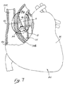
- A
- = Aorta
- AA
- = Aortic Annulus
- M
- = Myocardium
- IVS
- = Interventricular Septum
- RV
- = Right Ventricle
- RA
- = Right Atrium
- LV
- = Left Ventricle
- SVC
- = Superior Vena Cava
Claims (14)
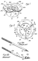
- An aortic valve sizing obturator apparatus (10) comprising:a cylindrical obturator body (12) having a top end, a bottom end, and an outer surface (14) having a first outer diameter;a flange member (18) formed about the top end of said cylindrical obturator body, said flange member having an upper surface (20), an under surface (22), and a second outer diameter, said second outer diameter being larger than said first outer diameter;
characterized by the undersurface of said flange member (18) having a non-planar, multi-curvate configuration. - The apparatus of Claim 1 wherein the non-planar, multi-curvate configuration of the undersurface of said flange member comprises:three spaced-apart peaks (24a, 24b, 24c) with three arcuate depressions (26a, 26b, 26c), each of said arcuate depressions extending between adjacent ones of said peaks.
- The apparatus of Claim 2 wherein said peaks are equidistantly spaced apart.
- The apparatus of Claim 1 wherein the entire annular flange is of said non-linear, multi-curvate configuration.
- The apparatus of Claim 4 wherein the upper surface (20) of said flange member (18) is coterminous with the top end of said cylindrical obturator body (12), and wherein the top end of said cylindrical obturator body (12) is also of said non-planar, multi-curvate configuration.
- The apparatus of Claim 1, wherein the cylindrical obturator body (12) is hollow and has an inner cylindrical surface (16).
- The apparatus of Claim 6 and further comprising: an inner cylindrical member (30) disposed longitudinally and coaxially within the cylindrical obturator body (12), said inner cylindrical member being rigidly affixed to said obturator body (12) and incorporating a handle connector apparatus whereby a separate handle member may be attached to said obturator apparatus.
- The apparatus of Claim 7 wherein said connector apparatus incorporated within said inner cylindrical member comprises:a hollow bore (34) extending longitudinally through at least a portion of said inner cylindrical member, and internal threads (36) formed within said hollow bore such that an externally threaded handle may be rotatably engaged therewith.
- The apparatus of Claim 7, wherein said inner cylindrical member is rigidly affixed to said obturator body by radial strut members (28a, 28b, 28c) extending inwardly from the inner surface of the cylindrical obturator body.
- The apparatus of Claim 9, wherein the multi-curvate configuration of the undersurface of said flange comprises:three spaced-apart peaks (24a,24b,24c) with three arcuate depressions (26a,26b,26c), each of said arcuate depressions extending between adjacent ones of said peaks, and wherein there are three of said radial strut members (28a,28b,28c) attached to the inner surface of the cylindrical obturator body at locations adjacent each of the spaced-apart peaks formed in the multi-curvate flange.
- The apparatus of Claim 1 wherein the obturator body and flange member are of an autoclavable thermoplastic material.
- A kit for determining the size of a prosthetic aortic heart valve to be implanted into a surgically-prepared aortic annulus within a mammalian heart, said kit comprising a plurality of sizing obturators according to Claim 1, wherein at least the first diameter of one of said sizing obturators is different than the first diameter of another of said sizing obturators.
- The kit of Claim 12 wherein the multi-curvate configuration of the undersurface of each said sizing obturator flange comprises:three circumferentially spaced-apart peaks with three arcuate depressions, each of said arcuate depressions extending between adjacent ones of said peaks.
- The kit of Claim 13 further including an elongate handle member alternately attachable to each of said sizing obturators, for inserting and subsequently removing selected ones of said obturators into said aortic annulus.
Applications Claiming Priority (3)
| Application Number | Priority Date | Filing Date | Title |
|---|---|---|---|
| US58381196A | 1996-01-05 | 1996-01-05 | |
| US583811 | 1996-01-05 | ||
| PCT/US1997/000189 WO1997025003A1 (en) | 1996-01-05 | 1997-01-02 | Sizing obturator for prosthetic aortic valves |
Publications (2)
| Publication Number | Publication Date |
|---|---|
| EP0873094A1 EP0873094A1 (en) | 1998-10-28 |
| EP0873094B1 true EP0873094B1 (en) | 1999-06-30 |
Family
ID=24334652
Family Applications (1)
| Application Number | Title | Priority Date | Filing Date |
|---|---|---|---|
| EP97905563A Expired - Lifetime EP0873094B1 (en) | 1996-01-05 | 1997-01-02 | Sizing obturator for prosthetic aortic valves |
Country Status (6)
| Country | Link |
|---|---|
| US (1) | US5814096A (en) |
| EP (1) | EP0873094B1 (en) |
| JP (1) | JP3822908B2 (en) |
| AU (1) | AU2241497A (en) |
| DE (1) | DE69700302T2 (en) |
| WO (1) | WO1997025003A1 (en) |
Families Citing this family (43)
| Publication number | Priority date | Publication date | Assignee | Title |
|---|---|---|---|---|
| US6019739A (en) * | 1998-06-18 | 2000-02-01 | Baxter International Inc. | Minimally invasive valve annulus sizer |
| US6383147B1 (en) | 1999-01-26 | 2002-05-07 | Edwards Lifesciences Corporation | Anatomical orifice sizers and methods of orifice sizing |
| DE60035495T2 (en) * | 1999-04-28 | 2008-03-20 | St. Jude Medical, Inc., St. Paul | Aortic Heart Lobe Prosthesis Measurement and Marking Device |
| US6610071B1 (en) * | 1999-07-26 | 2003-08-26 | Beth Israel Deaconess Medical Center | Suture system |
| US6350281B1 (en) | 1999-09-14 | 2002-02-26 | Edwards Lifesciences Corp. | Methods and apparatus for measuring valve annuluses during heart valve-replacement surgery |
| US6678962B1 (en) * | 1999-11-17 | 2004-01-20 | Cardiomend Llc | Device and method for assessing the geometry of a heart valve |
| US6598307B2 (en) * | 1999-11-17 | 2003-07-29 | Jack W. Love | Device and method for assessing the geometry of a heart valve |
| US6719785B2 (en) | 2001-05-17 | 2004-04-13 | St. Jude Medical, Inc. | Aortic heart valve prosthesis implantation tool |
| US7510573B2 (en) * | 2003-03-25 | 2009-03-31 | Shlomo Gabbay | Sizing apparatus |
| US7258698B2 (en) | 2003-10-17 | 2007-08-21 | Medtronic, Inc. | Prosthetic heart valve sizer assembly with flexible sizer body |
| ITTO20040135A1 (en) | 2004-03-03 | 2004-06-03 | Sorin Biomedica Cardio Spa | CARDIAC VALVE PROSTHESIS |
| ITTO20050074A1 (en) | 2005-02-10 | 2006-08-11 | Sorin Biomedica Cardio Srl | CARDIAC VALVE PROSTHESIS |
| US20080262603A1 (en) * | 2007-04-23 | 2008-10-23 | Sorin Biomedica Cardio | Prosthetic heart valve holder |
| US8006535B2 (en) | 2007-07-12 | 2011-08-30 | Sorin Biomedica Cardio S.R.L. | Expandable prosthetic valve crimping device |
| GB0716403D0 (en) * | 2007-08-22 | 2007-10-03 | Benoist Girard Sas | Trial prosthetic neck component |
| US9848981B2 (en) | 2007-10-12 | 2017-12-26 | Mayo Foundation For Medical Education And Research | Expandable valve prosthesis with sealing mechanism |
| US20090192602A1 (en) * | 2008-01-25 | 2009-07-30 | Medtronic, Inc. | Deformable Sizer and Holder Devices for Minimally Invasive Cardiac Surgery |
| US20090192600A1 (en) * | 2008-01-25 | 2009-07-30 | Ryan Timothy R | Sizing device having two sizers and methods of use |
| US8317696B2 (en) * | 2008-12-15 | 2012-11-27 | Coroneo, Inc. | Surgical tool for measurement of valve annulus and cusp geometry |
| ES2551694T3 (en) | 2008-12-23 | 2015-11-23 | Sorin Group Italia S.R.L. | Expandable prosthetic valve with anchoring appendages |
| US8715207B2 (en) | 2009-03-19 | 2014-05-06 | Sorin Group Italia S.R.L. | Universal valve annulus sizing device |
| EP2410947B1 (en) | 2009-03-26 | 2015-05-20 | Sorin Group USA, Inc. | Annuloplasty sizers for minimally invasive procedures |
| US20110022165A1 (en) | 2009-07-23 | 2011-01-27 | Edwards Lifesciences Corporation | Introducer for prosthetic heart valve |
| US20110251598A1 (en) | 2010-04-13 | 2011-10-13 | Shigeyuki Ozaki | Instrument of patterning cusp for cardiac valve reconstruction and component thereof |
| IT1400327B1 (en) | 2010-05-21 | 2013-05-24 | Sorin Biomedica Cardio Srl | SUPPORT DEVICE FOR VALVULAR PROSTHESIS AND CORRESPONDING CORRESPONDENT. |
| EP2486893B1 (en) | 2011-02-14 | 2017-07-05 | Sorin Group Italia S.r.l. | Sutureless anchoring device for cardiac valve prostheses |
| EP2486894B1 (en) | 2011-02-14 | 2021-06-09 | Sorin Group Italia S.r.l. | Sutureless anchoring device for cardiac valve prostheses |
| US10182913B2 (en) | 2012-10-12 | 2019-01-22 | Nikola Dobrilovic | Heart valve sizing ring for valve-sparing aortic root remodeling procedures |
| US9889009B2 (en) | 2011-10-26 | 2018-02-13 | Nikola Dobrilovic | Heart valve sizing ring and method |
| US9839516B2 (en) | 2012-04-27 | 2017-12-12 | Nikola Dobrilovic | Prosthetic device for heart valve reinforcement and remodeling procedures |
| US11872135B2 (en) | 2012-10-12 | 2024-01-16 | Nikola Dobrilovic, LLC | Heart valve sizing ring for valve-sparing aortic root remodeling procedures |
| US9345574B2 (en) | 2011-12-09 | 2016-05-24 | Edwards Lifesciences Corporation | Force-based heart valve sizer |
| US9277996B2 (en) | 2011-12-09 | 2016-03-08 | Edwards Lifesciences Corporation | Force-based heart valve sizer |
| US9301835B2 (en) | 2012-06-04 | 2016-04-05 | Edwards Lifesciences Corporation | Pre-assembled bioprosthetic valve and sealed conduit |
| US9585748B2 (en) | 2012-09-25 | 2017-03-07 | Edwards Lifesciences Corporation | Methods for replacing a native heart valve and aorta with a prosthetic heart valve and conduit |
| US9844436B2 (en) | 2012-10-26 | 2017-12-19 | Edwards Lifesciences Corporation | Aortic valve and conduit graft implant tool |
| US9149360B2 (en) | 2013-03-12 | 2015-10-06 | Edwards Lifesciences Corporation | Dynamic annuloplasty ring sizer |
| ES2860600T3 (en) | 2013-03-13 | 2021-10-05 | Jenesis Surgical Llc | Articulated commissure valve endoprosthesis |
| US10119882B2 (en) | 2015-03-10 | 2018-11-06 | Edwards Lifesciences Corporation | Surgical conduit leak testing |
| US11337805B2 (en) | 2018-01-23 | 2022-05-24 | Edwards Lifesciences Corporation | Prosthetic valve holders, systems, and methods |
| CN112437649A (en) | 2018-05-23 | 2021-03-02 | 索林集团意大利有限责任公司 | Heart valve prosthesis |
| WO2019224582A1 (en) | 2018-05-23 | 2019-11-28 | Sorin Group Italia S.R.L. | A loading system for an implantable prosthesis and related loading method |
| USD908874S1 (en) | 2018-07-11 | 2021-01-26 | Edwards Lifesciences Corporation | Collapsible heart valve sizer |
Family Cites Families (8)
| Publication number | Priority date | Publication date | Assignee | Title |
|---|---|---|---|---|
| GB2083362B (en) * | 1977-12-29 | 1982-11-24 | Yeshiva University Albert Eins | Disposable heart valve unit |
| US4211241A (en) * | 1978-03-03 | 1980-07-08 | Kastec Corporation | Heart valve sizing gauge |
| US4388735A (en) * | 1980-11-03 | 1983-06-21 | Shiley Inc. | Low profile prosthetic xenograft heart valve |
| US4626255A (en) * | 1983-09-23 | 1986-12-02 | Christian Weinhold | Heart valve bioprothesis |
| US5042161A (en) * | 1985-10-07 | 1991-08-27 | Joseph Hodge | Intravascular sizing method and apparatus |
| US5360014A (en) * | 1993-11-10 | 1994-11-01 | Carbomedics, Inc. | Sizing apparatus for heart valve with supra annular suture ring |
| US5489296A (en) * | 1993-12-17 | 1996-02-06 | Autogenics | Heart valve measurement tool |
| US5531785A (en) * | 1994-05-06 | 1996-07-02 | Autogenics, Inc. | Prosthetic heart valve holder |
-
1997
- 1997-01-02 JP JP52534597A patent/JP3822908B2/en not_active Expired - Lifetime
- 1997-01-02 AU AU22414/97A patent/AU2241497A/en not_active Abandoned
- 1997-01-02 DE DE69700302T patent/DE69700302T2/en not_active Expired - Lifetime
- 1997-01-02 EP EP97905563A patent/EP0873094B1/en not_active Expired - Lifetime
- 1997-01-02 WO PCT/US1997/000189 patent/WO1997025003A1/en active IP Right Grant
- 1997-10-24 US US08/960,083 patent/US5814096A/en not_active Expired - Lifetime
Also Published As
| Publication number | Publication date |
|---|---|
| JP3822908B2 (en) | 2006-09-20 |
| US5814096A (en) | 1998-09-29 |
| AU2241497A (en) | 1997-08-01 |
| WO1997025003A1 (en) | 1997-07-17 |
| EP0873094A1 (en) | 1998-10-28 |
| DE69700302T2 (en) | 2000-03-23 |
| DE69700302D1 (en) | 1999-08-05 |
| JP2000502937A (en) | 2000-03-14 |
Similar Documents
| Publication | Publication Date | Title |
|---|---|---|
| EP0873094B1 (en) | Sizing obturator for prosthetic aortic valves | |
| US20200246139A1 (en) | Heart Valve Assemblies | |
| US10639148B2 (en) | Method of placing a prosthetic valve assembly in a patient's circulatory system | |
| CA2526347C (en) | Apparatus and methods for repair of a cardiac valve | |
| AU2015221440B2 (en) | A replacement valve | |
| US7503930B2 (en) | Prosthetic cardiac valves and systems and methods for implanting thereof | |
| US8568473B2 (en) | Systems and methods for enabling heart valve replacement | |
| EP1212011B1 (en) | Apparatus for measuring valve annuluses during heart valve-replacement surgery | |
| US7727276B2 (en) | System and method for heart valve replacement | |
| AU2001295074B2 (en) | Minimally-invasive annuloplasty repair segment delivery template system | |
| AU728106B2 (en) | Stentless bioprosthetic heart valve with coronary protuberances | |
| US20040059413A1 (en) | Suture template for facilitating implantation of a prosthetic heart valve | |
| AU2001295074A1 (en) | Minimally-invasive annuloplasty repair segment delivery template system | |
| WO2012103173A2 (en) | Devices and methods for surgical and percutaneous repair of heart valve lesions | |
| CA2241842C (en) | Sizing obturator for prosthetic aortic valves | |
| US20030109921A1 (en) | System for implanting prosthetic heart valves | |
| AU2017204546B2 (en) | Prosthetic insert for improving heart valve function | |
| Hvass et al. | The stentless Bravo 300 aortic porcine xenograft: supra-annular versus annular implantation |
Legal Events
| Date | Code | Title | Description |
|---|---|---|---|
| PUAI | Public reference made under article 153(3) epc to a published international application that has entered the european phase |
Free format text: ORIGINAL CODE: 0009012 |
|
| 17P | Request for examination filed |
Effective date: 19980612 |
|
| AK | Designated contracting states |
Kind code of ref document: A1 Designated state(s): DE FR GB |
|
| GRAG | Despatch of communication of intention to grant |
Free format text: ORIGINAL CODE: EPIDOS AGRA |
|
| 17Q | First examination report despatched |
Effective date: 19981105 |
|
| GRAG | Despatch of communication of intention to grant |
Free format text: ORIGINAL CODE: EPIDOS AGRA |
|
| GRAH | Despatch of communication of intention to grant a patent |
Free format text: ORIGINAL CODE: EPIDOS IGRA |
|
| GRAH | Despatch of communication of intention to grant a patent |
Free format text: ORIGINAL CODE: EPIDOS IGRA |
|
| GRAA | (expected) grant |
Free format text: ORIGINAL CODE: 0009210 |
|
| AK | Designated contracting states |
Kind code of ref document: B1 Designated state(s): DE FR GB |
|
| REF | Corresponds to: |
Ref document number: 69700302 Country of ref document: DE Date of ref document: 19990805 |
|
| ET | Fr: translation filed | ||
| PLBE | No opposition filed within time limit |
Free format text: ORIGINAL CODE: 0009261 |
|
| STAA | Information on the status of an ep patent application or granted ep patent |
Free format text: STATUS: NO OPPOSITION FILED WITHIN TIME LIMIT |
|
| 26N | No opposition filed | ||
| REG | Reference to a national code |
Ref country code: GB Ref legal event code: IF02 |
|
| REG | Reference to a national code |
Ref country code: FR Ref legal event code: PLFP Year of fee payment: 20 |
|
| PGFP | Annual fee paid to national office [announced via postgrant information from national office to epo] |
Ref country code: GB Payment date: 20151224 Year of fee payment: 20 |
|
| PGFP | Annual fee paid to national office [announced via postgrant information from national office to epo] |
Ref country code: FR Payment date: 20151222 Year of fee payment: 20 |
|
| PGFP | Annual fee paid to national office [announced via postgrant information from national office to epo] |
Ref country code: DE Payment date: 20151217 Year of fee payment: 20 |
|
| REG | Reference to a national code |
Ref country code: DE Ref legal event code: R071 Ref document number: 69700302 Country of ref document: DE |
|
| REG | Reference to a national code |
Ref country code: GB Ref legal event code: PE20 Expiry date: 20170101 |
|
| PG25 | Lapsed in a contracting state [announced via postgrant information from national office to epo] |
Ref country code: GB Free format text: LAPSE BECAUSE OF EXPIRATION OF PROTECTION Effective date: 20170101 |