EP0872987A2 - Procédé, appareil et moyen de stockage informatique contenant un programme pour fournir des informations - Google Patents
Procédé, appareil et moyen de stockage informatique contenant un programme pour fournir des informations Download PDFInfo
- Publication number
- EP0872987A2 EP0872987A2 EP98105893A EP98105893A EP0872987A2 EP 0872987 A2 EP0872987 A2 EP 0872987A2 EP 98105893 A EP98105893 A EP 98105893A EP 98105893 A EP98105893 A EP 98105893A EP 0872987 A2 EP0872987 A2 EP 0872987A2
- Authority
- EP
- European Patent Office
- Prior art keywords
- server
- information
- client
- network
- storage means
- Prior art date
- Legal status (The legal status is an assumption and is not a legal conclusion. Google has not performed a legal analysis and makes no representation as to the accuracy of the status listed.)
- Withdrawn
Links
Images


Classifications
-
- H—ELECTRICITY
- H04—ELECTRIC COMMUNICATION TECHNIQUE
- H04N—PICTORIAL COMMUNICATION, e.g. TELEVISION
- H04N21/00—Selective content distribution, e.g. interactive television or video on demand [VOD]
- H04N21/60—Network structure or processes for video distribution between server and client or between remote clients; Control signalling between clients, server and network components; Transmission of management data between server and client, e.g. sending from server to client commands for recording incoming content stream; Communication details between server and client
- H04N21/61—Network physical structure; Signal processing
- H04N21/6106—Network physical structure; Signal processing specially adapted to the downstream path of the transmission network
-
- H—ELECTRICITY
- H04—ELECTRIC COMMUNICATION TECHNIQUE
- H04L—TRANSMISSION OF DIGITAL INFORMATION, e.g. TELEGRAPHIC COMMUNICATION
- H04L12/00—Data switching networks
- H04L12/28—Data switching networks characterised by path configuration, e.g. LAN [Local Area Networks] or WAN [Wide Area Networks]
-
- H—ELECTRICITY
- H04—ELECTRIC COMMUNICATION TECHNIQUE
- H04N—PICTORIAL COMMUNICATION, e.g. TELEVISION
- H04N21/00—Selective content distribution, e.g. interactive television or video on demand [VOD]
- H04N21/20—Servers specifically adapted for the distribution of content, e.g. VOD servers; Operations thereof
- H04N21/21—Server components or server architectures
-
- H—ELECTRICITY
- H04—ELECTRIC COMMUNICATION TECHNIQUE
- H04N—PICTORIAL COMMUNICATION, e.g. TELEVISION
- H04N21/00—Selective content distribution, e.g. interactive television or video on demand [VOD]
- H04N21/20—Servers specifically adapted for the distribution of content, e.g. VOD servers; Operations thereof
- H04N21/23—Processing of content or additional data; Elementary server operations; Server middleware
-
- H—ELECTRICITY
- H04—ELECTRIC COMMUNICATION TECHNIQUE
- H04N—PICTORIAL COMMUNICATION, e.g. TELEVISION
- H04N21/00—Selective content distribution, e.g. interactive television or video on demand [VOD]
- H04N21/40—Client devices specifically adapted for the reception of or interaction with content, e.g. set-top-box [STB]; Operations thereof
- H04N21/41—Structure of client; Structure of client peripherals
- H04N21/414—Specialised client platforms, e.g. receiver in car or embedded in a mobile appliance
- H04N21/4143—Specialised client platforms, e.g. receiver in car or embedded in a mobile appliance embedded in a Personal Computer [PC]
-
- H—ELECTRICITY
- H04—ELECTRIC COMMUNICATION TECHNIQUE
- H04N—PICTORIAL COMMUNICATION, e.g. TELEVISION
- H04N21/00—Selective content distribution, e.g. interactive television or video on demand [VOD]
- H04N21/40—Client devices specifically adapted for the reception of or interaction with content, e.g. set-top-box [STB]; Operations thereof
- H04N21/47—End-user applications
- H04N21/472—End-user interface for requesting content, additional data or services; End-user interface for interacting with content, e.g. for content reservation or setting reminders, for requesting event notification, for manipulating displayed content
- H04N21/47202—End-user interface for requesting content, additional data or services; End-user interface for interacting with content, e.g. for content reservation or setting reminders, for requesting event notification, for manipulating displayed content for requesting content on demand, e.g. video on demand
-
- H—ELECTRICITY
- H04—ELECTRIC COMMUNICATION TECHNIQUE
- H04N—PICTORIAL COMMUNICATION, e.g. TELEVISION
- H04N21/00—Selective content distribution, e.g. interactive television or video on demand [VOD]
- H04N21/60—Network structure or processes for video distribution between server and client or between remote clients; Control signalling between clients, server and network components; Transmission of management data between server and client, e.g. sending from server to client commands for recording incoming content stream; Communication details between server and client
- H04N21/61—Network physical structure; Signal processing
- H04N21/6156—Network physical structure; Signal processing specially adapted to the upstream path of the transmission network
- H04N21/6175—Network physical structure; Signal processing specially adapted to the upstream path of the transmission network involving transmission via Internet
-
- H—ELECTRICITY
- H04—ELECTRIC COMMUNICATION TECHNIQUE
- H04N—PICTORIAL COMMUNICATION, e.g. TELEVISION
- H04N7/00—Television systems
- H04N7/16—Analogue secrecy systems; Analogue subscription systems
- H04N7/173—Analogue secrecy systems; Analogue subscription systems with two-way working, e.g. subscriber sending a programme selection signal
- H04N7/17309—Transmission or handling of upstream communications
- H04N7/17336—Handling of requests in head-ends
Definitions
- the present invention relates to an apparatus for providing specific information on demand and a method thereof and a computer-readable storage medium retaining a program for providing information.
- a video on demand (VOD) system has been commercialized for distributing video data and audio data and so on from a server on a client's demand for obtaining a movie, a program, etc.
- VOD video on demand
- a client's side terminal unit uses dedicated software for communications with a server.
- the dedicated software provides a user interface, using a programming language such as the C language, which responds to demands of a client input at a client's side terminal unit.
- the dedicated software is designed to conform to sections for communicating with server control software.
- the VOD system may be used by various clients including a museum, a showroom, a small theater and a shop. It is therefore required to provide a client's side terminal unit with a user interface specifically designed for each user. Each user interface may dynamically change with time and seasons or with an exhibition at a museum and so on.
- VOD system for use by various clients is the difficulty in creating a renewed user interface conforming to the client's demands. That is, for introducing the VOD system, it is required to newly create a means for communications between a client's side terminal unit and a server in a physical form as well as in a form of software. On the server's side, server control software dedicated to the VOD system is required for controlling the server. On the other hand, it is required for the client's side terminal unit to communicate with the server control software on the server's side through client software operating on the terminal unit for requesting the server control software for reproducing image data or audio data and so on.
- An apparatus of the invention for providing information comprises a means for receiving a demand for providing information from a client through a network, using a world wide web as a system for providing a link to information on an Internet, and a means for sending information to the client through a transmission line different from the network in response to the demand for providing information from the client received by the means for receiving a demand.
- a method of the invention for providing information comprises the steps of receiving a demand for providing information from a client through a network, using the world wide web as a system for providing a link to information on the Internet, and sending information to the client through a transmission line different from the network in response to the received demand for providing information from the client.
- a computer-readable storage medium stores a program for providing information which allows a computer to implement a function of receiving a demand for providing information from a client through a network, using the world wide web as a system for providing a link to information on the Internet, and a function of sending information to the client through a transmission line different from the network in response to the demand for providing information from the client received by the function of receiving a demand.
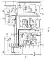
- Fig. 1 is a block diagram illustrating a main part of a VOD system including an information providing apparatus of an embodiment of the invention.
- Fig. 2 is a block diagram illustrating an overall configuration of the VOD system of the embodiment of the invention.
- Fig. 3 is a block diagram illustrating an example of a computer used as a server computer and a client computer in Fig. 1.
- Fig. 4 is a block diagram illustrating an example of a VOD server in Fig. 1.
- Fig. 5 is a table for showing an example of a relationship table stored in the server computer in Fig. 1.
- Fig. 6 is a chart for illustrating an operation of the VOD system of the embodiment of the invention.
- Fig. 7 illustrates a relationship between a frame outputted from the client computer and a frame shown on a display.
- Fig. 8 illustrates the VOD system of the embodiment connected to an external Internet.
- Fig. 9 illustrates the client computer of the embodiment connected to a plurality of server computers for VOD server control.
- Fig. 10 illustrates an example of a CATV system.
- Fig. 11 is a block diagram illustrating a modification of the VOD server of the embodiment of the invention.
- Fig. 12 illustrates an application of the invention to an auto-changer system using disk players.
- Fig. 13 illustrates an application of the invention to an auto-changer system using video cassette recorders.
- Fig. 1 is a block diagram illustrating a main part of a VOD system including an apparatus for providing information of an embodiment of the invention.
- the VOD system is a system for providing specific video information and audio information through a plurality of channels on demands of a plurality of clients for providing information.
- the VOD system comprises: a VOD server 11 for storing information to be provided for clients and sending out a specific piece of information in response to instructions; a server computer 12 for controlling the VOD server 11; a client computer 13 for sending a request for providing information to the server computer 12; a rate converter 14 for converting video signals outputted from the client computer 13 into video signals for display on a display 16; a switcher 15 for switching between video signals sent from the VOD server 11 via a high bandwidth, independent link 19 and video signals outputted from the rate converter 14 for output to the display 16 for displaying a video image.
- the apparatus for providing information of the embodiment is made up of the VOD server 11 and the server computer 12.
- the VOD server 11 has output channels for a plurality of video data and audio data (referred to as AV data in the following description).
- the VOD server 11 and the server computer 12 are connected to each other through a serial transmission line 17 utilizing a serial interface such as an RS232C.
- the server computer 12 and the client computer 13 are connected to each other through a network 18, such as an Internet, using an Ethernet, for example.
- a network 18 such as an Internet, using an Ethernet, for example.
- a plurality of client computers 13 each receiving information from the VOD server 11 are connectable to the network 18 and a separate channel or link 19.
- Each switcher 15 corresponding to one of the client computers 13 is connected to one of the plurality of output channels of the VOD server 11 through the separate transmission line 19.
- VOD server 11 and the server computer 12 are called a server's side.
- the client computer 13, the rate converter 14, the switcher 15 and the display 16 are called a client's side.
- the server computer 12 comprises: a world wide web (WWW) server 21 for management and distribution and so on of information carried on the Internet using a WWW as a system for allowing a link to information on the Internet; a server controller 22 for controlling the VOD server 11 by giving a command to the VOD server 11 through the serial transmission line 17; a server interface 23 for interfacing between the WWW server 21 and the server controller 22; and a hypertext markup language (HTML) file disk 24 for storing an HTML document written in the HTML as a hypertext language.
- the HTML file disk 24 is accessible from either the WWW server 21 or the server controller 22.
- the WWW server 21, the server controller 22 and the server interface 23 are each implemented by reloadable software (programs).
- the HTML file disk 24 is implemented by a hard disk in the server computer 12.
- the server computer 12 shown in Fig. 1 corresponds to a means for receiving a demand (a function of receiving a demand), a means for generating information indicating sending (a function of generating information indicating sending) and a means for sending a program (a function of sending a program).
- the VOD server 11 corresponds to a means for sending information (a function for sending information).
- the server computer 12 uses Windows NT® (a registered trademark of Microsoft Corporation), for example, for an operating system.
- the WWW server 21 is implemented through installing software such as Microsoft-Internet information server (IISTM, a trademark of Microsoft Corporation).
- the server interface 23 is, for example, implemented by software designed in compliance with an Internet server application programming interface (ISAPI) as additional software for providing extensions for the WWW server implemented by the IIS.
- ISAPI Internet server application programming interface
- the client computer 13 comprises: a parallel input/output (PIO) controller 26 for controlling parallel inputs and outputs and a WWW browser 27 for accessing a WWW server on the Internet using the WWW.
- PIO parallel input/output
- a suitable browser might be the commercially available Internet ExplorerTM (a trademark of Microsoft Corporation) or Netscape Navigator® (a registered trademark of Netscape Communications Corporation).
- the PIO controller 26 and the WWW browser 27 are each implemented by software (a program).
- the PIO controller 26 has a function of controlling the switcher 15 at commands from the WWW server 21.
- HTML documents are stored on the HTML file disk 24 in the server computer 12.
- the HTML documents include control codes for implementing a user interface using the WWW browser 27.
- the control codes included in the HTML documents include control codes for controlling the VOD server 11.
- the WWW browser 27 sends a request via the network 18 for controlling the VOD server 11 to the WWW server 21 when a control code for controlling the VOD server 11 is included in an HTML document distributed via the network 18 from the WWW server 21.
- the control request is sent from the WWW server 21 to the server interface 23.
- the server interface 23 gives an instruction to the server controller 22 for executing control at the control request.
- the server controller 22 gives a command to the VOD server 11 through the serial transmission line 17 to control the VOD server 11.
- the server controller 22 has data of a table indicating a relationship between the output channels and Internet addresses (IP addresses), that is, addresses on the network 18 of the plurality of client computers 13.
- Fig. 5 shows an example of such a relationship table.
- the relationship table is made by an administrator of the VOD system.
- the server controller 22 refers to the relationship table to determine the output channel corresponding to the Internet address of the client computer 13 that made the request.
- the server controller 22 then controls the VOD server 11 so that the requested information is sent through the corresponding separate link 19 to the client computer 13 that made the request for providing the information.
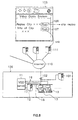
- Fig. 2 is a block diagram illustrating an overall configuration of the VOD system of the embodiment.
- the VOD system shown comprises: the server computer 12 connected to the network 18; the VOD server 11 whose operation is controlled by the server computer 12; and four terminal units 31 to 34 of the client's side each connected to the network 18.
- the VOD server 11 has six output channels ch1 to ch6 for AV data.
- the terminal units 31 to 34 receive AV data from the respective output channels ch1 to ch4 of the VOD server 11 via the separate links 19.
- V and A each represent video data and audio data, respectively.
- the terminal unit 31 has a configuration similar to that of the client's side in Fig. 1.
- the terminal unit 31 comprises: a client computer 13 connected to the network 18; a rate converter 14 for converting video signals outputted from the client computer 13 into video signals for display on a display 16; a switcher 15 for switching between video signals sent from the VOD server 11 and video signals outputted from the rate converter 14 for output; and a display 16 for receiving video signals outputted from the switcher 15 and displaying a video image.
- the switcher 15 in this example further has a function of switching between audio signals sent from the VOD server 11 and audio signals outputted from the client computer 13.
- the terminal unit 31 further comprises active speakers 36 and headphones 37 for receiving audio signals outputted from the switcher 15 for audio output; and a trackball 38 connected to the client computer 13.
- the client computer 13 has a function of receiving video signals from an external source for manipulation. Video signals sent from the VOD server 11 are inputted to the client computer 13 as well.
- the terminal unit 32 comprises two head-mount displays 39 instead of the display 16, the active speakers 36 and the headphones 37 in the terminal unit 31.
- the head-mount displays 39 each incorporate speakers and receive video and audio signals outputted from the switcher 15 for image display and audio output.
- the terminal unit 33 comprises: a client computer 13 connected to the network 18; a touch monitor 41 for displaying video signals outputted from the client computer 13 and for functioning as a touch panel used for giving instructions to the client computer 13; active speakers 42 and headphones 43 for receiving audio signals outputted from the VOD server 11 and audio signals outputted from the client computer 13 for audio output.
- the client computer 13 in the terminal unit 33 has a function of receiving video signals from an external source for manipulation. Video signals sent from the VOD server 11 are inputted to the client computer 13 as well.
- the client computer 13 further has a function for overlaying an image made of video signals sent from the VOD server 11 on a frame created by the client computer 13 on the touch monitor 41. Another function of the client computer 13 is controlling the overlay display at commands from the WWW server 21.
- the terminal unit 34 comprises: a client computer 13 connected to the network 18; a touch panel 44 for displaying video signals outputted from the client computer 13 and for giving instructions to the client computer 13; a display 45 for receiving video signals sent from the VOD server 11 for video image display; and an audio system 46 for receiving audio signals outputted from the VOD server 11 for audio output.
- Fig. 3 is a block diagram illustrating an example of a computer used as the server computer 12 and the client computer 13 in Fig. 1.
- the computer comprises: a central processing unit (CPU) 51; read only memory (ROM) 52; random access memory (RAM) 53; an interface (shown as in I/F in the Figure) 54 for a display; an interface 60 for connection with the network 18; and a bus 50 for connecting the constituents.
- the computer further comprises: a hard disk 62; a CD-ROM drive 63; a floppy disk drive 64; a keyboard 65; and a mouse 66, each connected to the bus 50 through separate interfaces 55 to 59, respectively.
- the CPU 51 executes an application program stored in any of the hard disk 62, a CD-ROM driven by the CD-ROM drive 63 and a floppy disk driven by the floppy disk drive 64, with the RAM 53 as a work area.
- a program for implementing the WWW server 21, the server controller 22 and the server interface 23 corresponds to a program for sending information of the embodiment.
- a CD-ROM or a floppy disk corresponds to a computer-readable storage medium retaining a program for sending information when a program for implementing the WWW server 21, the server controller 22 and the server interface 23 in the server computer 12 is stored on either the CD-ROM driven by the CD-ROM drive 63 or the floppy disk driven by the floppy disk drive 64 and the program stored thereon is then installed on the hard disk 62.
- Fig. 4 is a block diagram illustrating an example of the VOD server in Fig. 1.
- the VOD server 11 shown comprises a storage section 71 and a control section 72.
- the storage section 71 has a plurality of hard disk drives (HDDs) 73 each for driving a hard disk.
- AV data to be provided for a client is stored on a hard disk driven by each HDD 73.
- the control section 72 has: a main CPU 74; a HDD interface (shown as HDD I/F) 75; AV data output sections 76 for every output channel connected to a separate link 19; and an internal bus 77 for interconnecting the constituents.
- the HDD interface 75 is connected to the HDDs 73 in the storage section 71.
- Each AV data output section 76 outputs AV data retrieved from the hard disk in the storage section 71 through the HDD interface 75 to a transmission line 19 in Fig. 1 through a corresponding channel 76.
- the main CPU 74 has a communication section 78 for communicating with the server computer 12 through the serial transmission line 17 in Fig.
- AV data I/F AV data I/F
- the communication section 78 and the AV data interface 79 are implemented through software.
- the main CPU 74 receives commands sent from the server computer 12 through the serial transmission line 17 at the communication section 78. In accordance with the commands the main CPU 74 controls the HDD 73 in the storage section 71 for retrieving desired AV data. The retrieved AV data is then outputted through the AV data output section 76 in accordance with the commands.
- VOD system shown in Fig. 1
- operations of the VOD server 11 and the server computer 12 as an apparatus for providing information of the embodiment.
- the following description serves for a method of providing information of the embodiment and a program for providing information stored in a computer-readable storage medium of the embodiment as well.
- the HTML file disk 24 in the server computer 12 stores HTML documents including control codes for implementing a user interface using the WWW browser 27.
- the control codes included in the HTML documents include control codes for controlling the VOD server 11.
- the WWW browser 27 is used for accessing the HTML document including a control code for controlling the VOD server 11.
- the WWW browser 27 gives a request for controlling the VOD server 11 to the WWW server 21 when control codes for controlling the VOD server 11 are included in an HTML document distributed from the WWW server 21.
- the control request is sent from the WWW server 21 in the server computer 12 to the server interface 23.
- the server interface 23 gives an instruction to the server controller 22 for executing control at the control request.
- the server controller 22 gives commands to the VOD server 11 through the serial transmission line 17 to control the VOD server 11.
- control code for controlling the VOD server 11 included in an HTML document In general, addition of application software to the WWW server 21 allows translation of an HTML document and a database search and so on. Using this function the embodiment of the invention achieves communications with the server controller 22 for controlling the VOD server 11, instead of performing translation of an HTML document and so on. Therefore a general-purpose code is used for the control code added to an HTML document. For example, the following code is used in practice for controlling the VOD server 11 using an HTML document:
- "Play Clip 1" is indicated on the display 16 on the client's side to which the HTML document is distributed including the above code. If “Play Clip 1" is selected (or clicked, for example) on a frame shown on the display 16 on the client's side, the WWW browser 27 sends the URL address: "http://www.addres/scrips/dll/VSRSI.dll?play?1&/home/play1.html” in the code to the WWW server 21. "VSRSI.dll?play?1&/home/play1.html” is a command for starting up software implementing the server interface 23. VSRSI is a name of the software implementing the server interface 23.
- the address and directory of the server where "VSRSI.dll” is located is "http://www.addres/script/dll”.
- the server interface 23 is thus started and operated.
- play?1&/home/play1.html is a parameter for controlling the VOD server 11, such as a number of a clip (an AV program).
- clip number 1 is designated for replay.
- a homepage (“/home/play1.html”) is designated to be displayed during replay of the clip.
- the server interface 23 started as described above also sends the Internet address of the client computer 13 having made the request to the server controller 22 in addition to the parameter.
- the server controller 22 analyzes the parameter and gives a command to the VOD server 11 through the transmission line 17 for controlling the VOD server 11.
- the server controller 22 designates the output channel corresponding to the Internet address, referring to the table indicating the relationship between the Internet addresses and the output channels.
- the server controller 22 gives the VOD server 11 a command for a time-consuming operation such as a replay of an image
- the server controller 22 creates a virtual image file (referred to as a virtual image in the following description) in an HTML directory in the HTML file disk 24 under control of the WWW server 21 if the command is correctly received by the VOD server 11.
- the virtual image indicates that the replay is under way.
- the server controller 22 informs the client computer 13 of the start of the replay and the termination of the replay request as well. If necessary, commands for switching video signals, such as switching of the switcher 15 and control of an overlay display, are sent to the client computer 13.
- the virtual image is created for each client.
- the server controller 22 periodically detects whether replay is terminated at the VOD server 11 through sensing a status of the VOD server 11. When a 15-minute clip is replayed, for example, intermittent detection is performed for 15 minutes. On detection of termination of replay, the server controller 22 deletes the virtual image. If a viewer requests that the replay be stopped, the server controller 22 controls the VOD server 11 so that the replay is stopped as well as deletes the virtual image.
- the client computer 13 On receiving the start of replay, the client computer 13 controls switching of video signals, if necessary, in accordance with the command. The client computer 13 then periodically accesses the virtual image in the server computer 12 through the use of the WWW browser 27. When the virtual image is deleted, the client computer 13 determines that the replay is terminated and controls switching of video signals, if necessary, to display a frame provided from the client computer 13 on the display 16.
- JavaTM applet For allowing periodical access of the client computer 13 to the virtual image, a JavaTM applet (JavaTM is a trademark of Sun Microsystems, Inc.), a small program written in the JavaTM language is used, for example.
- an applet may be included in an HTML document sent from the WWW server 21 to the WWW browser 27 so that the WWW browser 27 calls the applet out of the HTML document for execution.
- the applet periodically accesses the virtual image and determines that a replay is under way while the virtual image exists.
- An example of the HTML document including the applet is shown below:
- Fig. 6 for describing a series of operations of the VOD system shown in Fig. 1 when the client computer 13 requests a replay of AV data, as an example.
- a page of an HTML document including a control code for controlling the VOD server 11 is selected through the use of the WWW browser 27 in the client computer 13 (step S1). Consequently, the WWW server 21 in the server computer 12 transfers the HTML document to the WWW browser 27 (step S2). As a result, a frame output from the client computer 13 based on the HTML document is shown on the display 16.
- Fig. 7 illustrates a relationship between a frame outputted from the client computer 13 and a frame shown on a display 16.
- a frame output from the client computer 13 is displayed on the display 16, such as the one shown in Fig. 7 with a numeral 81.
- the WWW browser 27 returns to the WWW server 21 a control code for controlling the VOD server 11 in the HTML document distributed from the WWW server 21 (step S3).
- the control code is specifically for controlling the server interface 23 in the server computer 12.
- an instruction for a replay of AV data is made by selecting a part indicating "Close Encounters with the Jovians" or "Star Truck" on the frame 81.
- the control request is sent from the WWW server 21 in the server computer 12 to the server interface 23. Consequently the server interface 23 is started (step S4).
- the server interface 23 having started then passes a parameter for controlling the VOD server 11 to the server controller 22 (step S5).
- the server interface 23 sends the Internet address of the client computer 13 having made the control request to the server controller 22.
- the server controller 22 analyzes the parameter and gives a command to the VOD server 11 through the transmission line 17 for controlling the VOD server 11 (step S6).
- the server controller 22 designates the output channel 76 corresponding to the Internet address, referring to the table indicating the relationship between the Internet addresses and the output channels.
- the VOD server 11 starts a replay following the command (step S7).
- the server controller 22 creates a virtual image in an HTML directory under control of the WWW server 21 (step S8).
- the virtual image indicates that the replay is under way.
- the server controller 22 informs the client computer 13 of the start of the replay and the completion of the replay request by transferring an HTML page to the client computer 13 through the WWW server 21 (step S9).
- An example of the screen display of the HTML page is shown with numeral 82 in Fig. 7.
- the Java applet may be inserted in the HTML page, for example.
- the server controller 22 sends commands for switching video signals, such as switching of the switcher 15 and control of an overlay display, to the client computer 13.
- the server controller 22 periodically detects whether the replay is terminated at the VOD server 11 through sensing a status of the VOD server 11 (step S10).
- the replay is terminated at the VOD server 11 (step S11) and the server controller 22 detects the termination of the replay (step S12).
- the server controller 22 then deletes the virtual image (step S13)
- the client computer 13 controls switching of video signals following the command, if necessary.
- the switcher 15 is controlled for selecting output data from the VOD server 11 (step S14).
- the frame shown on the display 16 is switched to a frame outputted from the VOD server 11 as shown in Fig. 7.
- a frame indicated with numeral 82 is shown on the display 16 with an operation of a keyboard or a mouse while the frame outputted from the VOD server 11 is displayed on the display 16.
- the client computer 13 periodically accesses the virtual image in the server computer 12 by means of a Java applet, for example (step S15).
- the WWW server 21 in the server computer 12 transfers the virtual image to the client computer 13 (step S16).
- the client computer 13 detects that the virtual image is deleted (step S17) and then determines that the replay is terminated and controls switching of video signals if necessary.
- the switcher 15 is controlled for selecting output data of the rate converter 14 (step S18).
- the operation for replay of AV data thus completes (step S19).
- the frame output 82 of the client computer 13 is shown on the display 16 as shown in Fig. 7, for example.
- An index 83 shown after the termination of replay is included in the frame 82 in the example shown in Fig. 7.
- the frame returns to the previous page (the frame 81) by selecting the index 83.
- the server computer 12 receives the request for controlling the VOD server 11 from the client computer 13 through the use of the WWW.
- the instruction is given to the VOD server 11 for controlling the VOD server 11.
- a user interface is created through the use of the WWW browser 27. It is therefore easy to create and customize a user interface conforming to client's demands.
- communication between the WWW server 21 and the WWW browser 27 is used. It is therefore no longer necessary to provide another means of communication.
- the embodiment of the invention therefore allows clients to change a user interface relatively easily.
- the embodiment facilitates changing a user interface at a museum and a small theater and so on as a client of a VOD system where a client-specific user interface is required and the user interface dynamically changes with time and seasons and with an exhibition at a museum and so on.
- a homepage may be created for controlling the VOD server 11, using the standard HTML.
- an actual user receiving information from the VOD server 11 may use the WWW browser 27 operating on the client computer 13 to select a clip on the homepage written in the HTML displayed by the WWW browser 27 and to control the VOD server 11 for replaying video and audio.
- the clip on the VOD server 11 is seen as a content (a video source) of the WWW browser 27 by the user of the WWW browser 27.
- the separable programs implement the software for receiving requests from the client's side through the use of the WWW (the program for implementing the server interface 23) and the software for controlling the VOD server 11 (the program for implementing the server controller 22).
- the software programs may be easily diverted to some other system by modifying the hardware-dependent software for controlling the VOD server 11. It is therefore easy to produce the hardware-specific software for controlling the hardware.
- the embodiment allows AV data to be sent from the VOD server 11 to the client's side through the transmission line 19 rather than the network 18.
- the transmission line 19 could be any high bandwidth transmission medium, for example, a coaxial cable, a fiber-optical cable, a microwave or satellite link, or the like.
- AV data is transferred at a higher rate without the restriction imposed by the more limited data transfer rate in the network 18.
- the embodiment of the invention provides the virtual image while the VOD server 11 is replaying or sending AV data.
- the virtual image is accessible from the client's side using the WWW through the network 18 as well as indicates that the VOD server 11 is replaying AV data.
- the client's side detects whether the replay of the AV data is terminated or not by periodically accessing the virtual image.
- the client may perform other operations using the WWW such as completely moving to another page without waiting for the termination of replay of the AV data as well as recognize the termination of replay of the AV data.
- the embodiment easily provides appropriate information for a plurality of clients. This is achieved through the table stored in the server computer 12, indicating the relationship between the network address of each of the plurality of client computers 13 connected to the network 18 and the channel of each of the clients. On receiving a request for replay of AV data from the client, the relationship table is referred to for sending AV data to the client having made the replay request through the channel corresponding to the client.
- Fig. 8 illustrates an example of a VOD system 100 utilized in a museum and so on, connected to the external Internet 110.
- the VOD system 100 in the example comprises a server computer 12 and a plurality of client computers 13 connected through a network 18 and a VOD server 11 controlled by the server computer 12.
- the VOD system 100 further comprises another WWW server computer 101 connected to the network 18.
- the network 18 in the VOD system 100 is connected to the external Internet 110 through a network bridge 102.
- the external Internet 110 is connected to a plurality of WWW server computers 111.
- a numeral 105 in Fig. 8 indicates an example of a homepage relating to replay of a clip.
- the homepage is controlled and distributed by the server computer 12 in the VOD system 100.
- the homepage includes an item 106 for giving an instruction for replay of a particular clip and an item 107 for giving an instruction for accessing information relating to the clip. If the user selects the item 106, the particular clip is replayed. If the user selects the item 107, the client computer 13 links up with specific one of the WWW server computers 111 connected to the external Internet 110 by means of the WWW browser 27 to receive information relating to the clip managed by the WWW server computer 111.
- the embodiment allows links to WWW servers throughout the world by the client providing a connection to the external Internet.
- the user may have an access to information relating to a clip, available in an external source while it is not necessary that the user recognizes its location. The amount of information of the applications of the VOD system is thus increased.
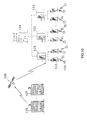
- Fig. 9 illustrates an example of one client computer 13 connected to a plurality of server computers 12 for controlling the VOD servers 11.
- the network 18 is connected to the external Internet 110 through a network bridge 102.
- the external Internet 110 is connected to a plurality of server computers 12.
- Each of the server computers 12 is connected to a separate VOD server 11 controlled by each of the server computers 12.
- the client computer 13 controls the plurality of VOD servers 11 by giving a control request to the plurality of server computers 12.
- a particular server computer 12 for controlling its corresponding VOD server 11 is designated with an Internet address. Therefore, once the Internet address of each of the server computers 12 and information of clips stored in the VOD servers 11 are known, the client computer 13 is capable of controlling the server computers 12 and the VOD servers 11 anywhere in the world as long as the server computers 12 are connected to the Internet 110 and an access block for security is released.
- the client computer 13 is capable of controlling the plurality of VOD servers 11.
- multi-channel control is achieved such as a multi-screen.
- database construction in the client computer 13 is easily performed if a command is provided for capturing a clip stored in the VOD server 11 in a remote place through the Internet.
- a command such as list.dll is provided in the server computer 12.
- the command list.dll is executed in the server computer 12 and the server computer 12 returns a text data created from data in the VOD server 11 in a form of an HTML document to the client computer 13.
- the status of the VOD server 11 in a remote place may be monitored by supplying a function of making a homepage indicating the status of the VOD server 11 to the WWW server 21 in the server computer 12.
- the status of the VOD server 11 includes hardware information of the VOD server 11 (the number of effective channels, the number of hard disks, the operational status of each hard disk, the record of failures and self-diagnostic check results) and use information (the number of clips stored and the remaining hard disk space).
- Such a function is useful for a community antenna television or cable television (CATV) station where the VOD server is used and remote control of the VOD server in an unattended relay station is performed.
- Fig. 10 illustrates an example of such a CATV system.
- the CATV system comprises: relay stations 122 for supplying programs to individual households 121; operational stations 123 for controlling the plurality of relay stations 122; a multi-system operational station 124 for controlling the plurality of operational stations 123; and a program sending station 125 for supplying programs to the relay stations 121 via a satellite 126 and the like.
- the monitoring function mentioned above is useful for such a CATV system with the program sending stations 125 each located in a designated area for supplying programs to each area and performing control by operating the plurality of unattended relay stations 122 from a main station.
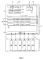
- FIG. 11 is a block diagram showing an example of a VOD server having a function of a server computer.
- a VOD server 120 shown comprises a storage section 71 and a control section 72.
- the control section 72 has a main CPU 74; an HDD interface (shown as HDD I/F) 75; AV data output sections 76 for respective output channels; and an internal bus 77 for interconnecting the constituents.
- the main CPU 74 has a WWW server 121, a server controller 122 and a server interface 123 each having a function similar to that of the WWW server 21, the server controller 22 and the server interface 23, respectively, in the server computer 12 in Fig. 1.
- the control section 72 has a function similar to that of the HTML file disk 24 in Fig. 1.
- the control section 72 further has an AV data interface (shown as AV data I/F) 79 for receiving AV data to be stored in the storage section 71 from an encoder not shown.
- the remainder of the configuration of the VOD server 120 in Fig. 11 is similar to that of the VOD server 11 in Fig. 4.
- the VOD server 120 shown in Fig. 11 may be provided for allowing a simpler connection on the server's side. As a result, costs may be reduced as well.
- the present invention is not limited to the VOD system described in the foregoing embodiments but may be applied to any other system wherein a specific device provides a specific information on demand of a client.
- Fig. 12 and Fig. 13 each illustrate an example of a system to which the invention is applicable.
- Fig. 12 illustrates an example of a configuration of an auto-changer system using disk players wherein the invention is applied.
- the auto-changer system comprises: a server computer 12 and a client computer 13 connected to each other through an network 18; and a disk cart system 130 controlled by the server computer 12 through a serial transmission line 133.
- the disk cart system 130 comprises a plurality of disk players 131 each replaying information from an optical disk and a disk changer 132 for placing an optical disk in each of the disk players 131. Information replayed by the disk player 131 is supplied to the client's side through a transmission line 134.
- the server computer 12 controls the disk cart system 130 instead of the VOD server 11 in Fig. 1.
- Fig. 13 illustrates an example of a configuration of an auto-changer system using video cassette recorders (VCRs) wherein the invention is applied.
- the auto-changer system comprises: a server computer 12 and a client computer 13 connected to each other through an network 18; and a VCR cart system 140 controlled by the server computer 12 through a serial transmission line 143.
- the VCR cart system 140 comprises a plurality of VCRs 141 each replaying information from a video cassette and a changer 142 for placing a video cassette in each of the VCRs 141.
- Information replayed by the VCR 141 is supplied to the client's side through a transmission line 144.
- the server computer 12 controls the VCR cart system 140 instead of the VOD server 11 in Fig. 1.
- HTML has been used throughout this application as the designation for the hypertext markup language preferably to be used, it should be apparent that the invention is not limited to the use of HTML per se and other hypertext languages, as they are developed, may also be suitable.
- HTML as a term in the description and claims is therefore to be construed as encompassing any suitable hypertext language which can be used by a compatible browser.
- the apparatus for providing information and the method thereof and the computer-readable storage medium retaining a program for providing information all allow receipt of a demand for providing information from a client through the network, using the world wide web.
- information required is sent to the client through a transmission line different from the network.
- a user interface is created on the client's side by means of the world wide web browser. It is therefore easy to create and customize a user interface conforming to client's demands. Because the information is sent to the client through the transmission line rather than the network, the information is transferred at a higher rate without the bandwidth restrictions imposed by the lower data transfer rate in the network.
- the invention allows a link to databases and relating information in an external source by the client providing a connection to the external Internet. It is therefore easy to obtain information relating to the provided information.
- the invention further allows the client to receive information from an apparatus in a remote place or a plurality of apparatuses through the Internet.
- the apparatus for providing information and the method thereof and the computer-readable storage medium retaining a program for providing information may further allow generation of information indicating sending.
- the information indicating sending indicates that information in demand is being sent and allows access of the client thereto through the network, using the world wide web while the information in demand is being sent.
- the client is thus allowed to perform another operation using the world wide web without waiting for completion of information being provided.
- the client is allowed to recognize completion of information being provided as well.
Applications Claiming Priority (12)
| Application Number | Priority Date | Filing Date | Title |
|---|---|---|---|
| JP8706697 | 1997-04-04 | ||
| JP10246697 | 1997-04-04 | ||
| JP9087067A JPH10283278A (ja) | 1997-04-04 | 1997-04-04 | 機器制御装置および方法ならびに機器制御用プログラムを記録したコンピュータ読み取り可能な記録媒体 |
| JP102466/97 | 1997-04-04 | ||
| JP9102465A JPH10285578A (ja) | 1997-04-04 | 1997-04-04 | 情報提供装置および方法ならびに情報提供用プログラムを記録したコンピュータ読み取り可能な記録媒体 |
| JP102465/97 | 1997-04-04 | ||
| JP10246597 | 1997-04-04 | ||
| JP9087066A JPH10285575A (ja) | 1997-04-04 | 1997-04-04 | 機器制御装置および方法ならびに機器制御用プログラムを記録したコンピュータ読み取り可能な記録媒体 |
| JP8706797 | 1997-04-04 | ||
| JP87066/97 | 1997-04-04 | ||
| JP87067/97 | 1997-04-04 | ||
| JP9102466A JPH10285579A (ja) | 1997-04-04 | 1997-04-04 | 情報提供装置および方法ならびに情報提供用プログラムを記録したコンピュータ読み取り可能な記録媒体 |
Publications (2)
| Publication Number | Publication Date |
|---|---|
| EP0872987A2 true EP0872987A2 (fr) | 1998-10-21 |
| EP0872987A3 EP0872987A3 (fr) | 2003-07-16 |
Family
ID=27467346
Family Applications (1)
| Application Number | Title | Priority Date | Filing Date |
|---|---|---|---|
| EP98105893A Withdrawn EP0872987A3 (fr) | 1997-04-04 | 1998-03-31 | Procédé, appareil et moyen de stockage informatique contenant un programme pour fournir des informations |
Country Status (3)
| Country | Link |
|---|---|
| EP (1) | EP0872987A3 (fr) |
| KR (1) | KR19980081096A (fr) |
| CN (1) | CN1208212A (fr) |
Cited By (9)
| Publication number | Priority date | Publication date | Assignee | Title |
|---|---|---|---|---|
| EP1037466A2 (fr) * | 1999-03-10 | 2000-09-20 | Sony Corporation | Système de diffusion de programme, méthode de diffusion de programme, émetteur et recepteur |
| EP1639486A2 (fr) * | 2003-06-30 | 2006-03-29 | Concurrent Computer Corporation | Procede, appareil et systeme permettant de gerer de maniere asymetrique des demandes de contenu et la remise de contenu |
| WO2006044052A2 (fr) * | 2004-10-18 | 2006-04-27 | Akimbo Systems Inc. | Procede et appareil de telechargement de contenu |
| EP1670145A1 (fr) * | 2003-09-22 | 2006-06-14 | Matsushita Electric Industrial Co., Ltd. | Dispositif electronique et son procede de commande |
| EP1865724A1 (fr) * | 2006-06-07 | 2007-12-12 | Sony NetServices GmbH | Système de vidéo sur demande. |
| EP2099221A3 (fr) * | 2003-11-05 | 2009-12-02 | Moosa Eisa Al Amri | Système et procédé de diffusion de vidéos par internet avec un son et une image nets |
| EP2547103A1 (fr) * | 2010-03-11 | 2013-01-16 | Sony Corporation | Appareil de remise de contenu, procédé de remise de contenu et serveur de transmission |
| US8839320B2 (en) | 2006-06-07 | 2014-09-16 | Andreas Martin | Video-on-demand system |
| US11468118B2 (en) | 2011-04-21 | 2022-10-11 | Touchstream Technologies, Inc. | Play control of content on a display device |
Families Citing this family (2)
| Publication number | Priority date | Publication date | Assignee | Title |
|---|---|---|---|---|
| US9113122B2 (en) | 1997-04-21 | 2015-08-18 | Rovi Guides, Inc. | Method and apparatus for time-shifting video and text in a text-enhanced television program |
| US6901511B1 (en) * | 2000-01-13 | 2005-05-31 | Casio Computer Co., Ltd. | Portable terminals, servers, systems, and their program recording mediums |
Citations (2)
| Publication number | Priority date | Publication date | Assignee | Title |
|---|---|---|---|---|
| EP0732835A2 (fr) * | 1995-03-13 | 1996-09-18 | AT&T Corp. | Architecture client/serveur avec Internet et réseau commuté public |
| US5944795A (en) * | 1996-07-12 | 1999-08-31 | At&T Corp. | Client-server architecture using internet and guaranteed quality of service networks for accessing distributed media sources |
-
1998
- 1998-03-31 EP EP98105893A patent/EP0872987A3/fr not_active Withdrawn
- 1998-04-03 CN CN98106204A patent/CN1208212A/zh active Pending
- 1998-04-04 KR KR1019980011978A patent/KR19980081096A/ko not_active Application Discontinuation
Patent Citations (2)
| Publication number | Priority date | Publication date | Assignee | Title |
|---|---|---|---|---|
| EP0732835A2 (fr) * | 1995-03-13 | 1996-09-18 | AT&T Corp. | Architecture client/serveur avec Internet et réseau commuté public |
| US5944795A (en) * | 1996-07-12 | 1999-08-31 | At&T Corp. | Client-server architecture using internet and guaranteed quality of service networks for accessing distributed media sources |
Cited By (25)
| Publication number | Priority date | Publication date | Assignee | Title |
|---|---|---|---|---|
| EP1037466A3 (fr) * | 1999-03-10 | 2004-04-21 | Sony Corporation | Système de diffusion de programme, méthode de diffusion de programme, émetteur et recepteur |
| EP1037466A2 (fr) * | 1999-03-10 | 2000-09-20 | Sony Corporation | Système de diffusion de programme, méthode de diffusion de programme, émetteur et recepteur |
| KR100722705B1 (ko) * | 1999-03-10 | 2007-06-04 | 소니 가부시끼 가이샤 | 프로그램 분배 장치, 프로그램 분배 방법, 송신 장치 및수신 장치 |
| US7257831B1 (en) | 1999-03-10 | 2007-08-14 | Sony Corportion | Program distribution system, method of program distribution, transmitter and receiver |
| EP1639486A2 (fr) * | 2003-06-30 | 2006-03-29 | Concurrent Computer Corporation | Procede, appareil et systeme permettant de gerer de maniere asymetrique des demandes de contenu et la remise de contenu |
| EP1639486A4 (fr) * | 2003-06-30 | 2006-10-04 | Concurrent Comp Corp | Procede, appareil et systeme permettant de gerer de maniere asymetrique des demandes de contenu et la remise de contenu |
| EP1670145A4 (fr) * | 2003-09-22 | 2008-08-13 | Matsushita Electric Ind Co Ltd | Dispositif electronique et son procede de commande |
| CN1856941B (zh) * | 2003-09-22 | 2010-04-28 | 松下电器产业株式会社 | 电子装置及其控制方法 |
| EP1670145A1 (fr) * | 2003-09-22 | 2006-06-14 | Matsushita Electric Industrial Co., Ltd. | Dispositif electronique et son procede de commande |
| EP2164260A1 (fr) * | 2003-11-05 | 2010-03-17 | Moosa Eisa Al Amri | Système et procédé de diffusion de vidéos par internet avec un son et une image nets |
| EP2099221A3 (fr) * | 2003-11-05 | 2009-12-02 | Moosa Eisa Al Amri | Système et procédé de diffusion de vidéos par internet avec un son et une image nets |
| WO2006044052A2 (fr) * | 2004-10-18 | 2006-04-27 | Akimbo Systems Inc. | Procede et appareil de telechargement de contenu |
| WO2006044052A3 (fr) * | 2004-10-18 | 2006-06-15 | Akimbo Systems Inc | Procede et appareil de telechargement de contenu |
| US8839320B2 (en) | 2006-06-07 | 2014-09-16 | Andreas Martin | Video-on-demand system |
| EP1865724A1 (fr) * | 2006-06-07 | 2007-12-12 | Sony NetServices GmbH | Système de vidéo sur demande. |
| US9479835B2 (en) | 2006-06-07 | 2016-10-25 | Sony Corporation | Video-on-demand system |
| US9888286B2 (en) | 2006-06-07 | 2018-02-06 | Sony Corporation | Video-on-demand system |
| US10721529B2 (en) | 2006-06-07 | 2020-07-21 | Sony Corporation | Video-on-demand system |
| EP2547103A1 (fr) * | 2010-03-11 | 2013-01-16 | Sony Corporation | Appareil de remise de contenu, procédé de remise de contenu et serveur de transmission |
| EP2547103A4 (fr) * | 2010-03-11 | 2013-12-11 | Sony Corp | Appareil de remise de contenu, procédé de remise de contenu et serveur de transmission |
| US9282351B2 (en) | 2010-03-11 | 2016-03-08 | Sony Corporation | Content delivery apparatus, content delivery method, and transmitting server |
| US11468118B2 (en) | 2011-04-21 | 2022-10-11 | Touchstream Technologies, Inc. | Play control of content on a display device |
| US11475062B2 (en) | 2011-04-21 | 2022-10-18 | Touchstream Technologies, Inc. | Play control of content on a display device |
| US11860938B2 (en) | 2011-04-21 | 2024-01-02 | Touchstream Technologies, Inc. | Play control of content on a display device |
| US11860937B2 (en) | 2011-04-21 | 2024-01-02 | Touchstream Technologies Inc. | Play control of content on a display device |
Also Published As
| Publication number | Publication date |
|---|---|
| CN1208212A (zh) | 1999-02-17 |
| EP0872987A3 (fr) | 2003-07-16 |
| KR19980081096A (ko) | 1998-11-25 |
Similar Documents
| Publication | Publication Date | Title |
|---|---|---|
| US6163779A (en) | Method of saving a web page to a local hard drive to enable client-side browsing | |
| US8341683B2 (en) | Convergence-enabled DVD and web system | |
| US5918012A (en) | Hyperlinking time-based data files | |
| US6732142B1 (en) | Method and apparatus for audible presentation of web page content | |
| US7096416B1 (en) | Methods and apparatuses for synchronizing mixed-media data files | |
| JP4347530B2 (ja) | 制御機器の少なくとも一つ以上の被制御機器制御方法及び装置 | |
| EP1811747B1 (fr) | Procédé et appareil pour stocker et restaurer des informations d'état d'une interface d'utilisateur à distance | |
| US20050039133A1 (en) | Controlling a presentation of digital content | |
| US6381567B1 (en) | Method and system for providing real-time personalization for web-browser-based applications | |
| US20020032701A1 (en) | Independent update and assembly of web page elements | |
| US20100306642A1 (en) | Co-browsing (java) scripted html documents | |
| US20030163566A1 (en) | Data access in a distributed environment | |
| JPH1188419A (ja) | 動画情報配信システムおよび方法 | |
| US20020054029A1 (en) | Interactive display system | |
| CA2401726A1 (fr) | Reseau domestique de gestion et de commande a base de navigateur | |
| WO2002065318A2 (fr) | Systeme et procede de creation d'une scene virtuelle et de presentation de contenu ameliore via la scene virtuelle | |
| WO2002017618A2 (fr) | Reseau distribue de publication | |
| EP0872987A2 (fr) | Procédé, appareil et moyen de stockage informatique contenant un programme pour fournir des informations | |
| CN114025140B (zh) | 用于b/s架构监控系统的一体化客户端 | |
| US20060218248A1 (en) | Contents distribution system, contents distribution method, and computer-readable storage medium therefor | |
| EP0737930A1 (fr) | Procédé et dispositif pour la représentation de présentations multimedia comme une bande dessinée | |
| US7444369B1 (en) | Director-controlled web session | |
| CA2763634A1 (fr) | Systemes et methodes permettant la lecture de video sur internet | |
| US7100191B1 (en) | Distributed publishing network | |
| KR20050048224A (ko) | 사용자 맞춤형 웹페이지 제공 방법 및 시스템 |
Legal Events
| Date | Code | Title | Description |
|---|---|---|---|
| PUAI | Public reference made under article 153(3) epc to a published international application that has entered the european phase |
Free format text: ORIGINAL CODE: 0009012 |
|
| AK | Designated contracting states |
Kind code of ref document: A2 Designated state(s): AT BE CH DE DK ES FI FR GB GR IE IT LI LU MC NL PT SE |
|
| AX | Request for extension of the european patent |
Free format text: AL;LT;LV;MK;RO;SI |
|
| PUAL | Search report despatched |
Free format text: ORIGINAL CODE: 0009013 |
|
| AK | Designated contracting states |
Designated state(s): AT BE CH DE DK ES FI FR GB GR IE IT LI LU MC NL PT SE |
|
| AX | Request for extension of the european patent |
Extension state: AL LT LV MK RO SI |
|
| RIC1 | Information provided on ipc code assigned before grant |
Ipc: 7H 04L 12/66 B Ipc: 7G 06F 17/30 B Ipc: 7H 04L 29/06 A |
|
| 17P | Request for examination filed |
Effective date: 20040115 |
|
| AKX | Designation fees paid |
Designated state(s): DE FR GB IT NL |
|
| 17Q | First examination report despatched |
Effective date: 20040824 |
|
| STAA | Information on the status of an ep patent application or granted ep patent |
Free format text: STATUS: THE APPLICATION IS DEEMED TO BE WITHDRAWN |
|
| 18D | Application deemed to be withdrawn |
Effective date: 20050104 |