EP0872585B1 - Loom with dobby and method for controlling such a loom - Google Patents
Loom with dobby and method for controlling such a loom Download PDFInfo
- Publication number
- EP0872585B1 EP0872585B1 EP97810245A EP97810245A EP0872585B1 EP 0872585 B1 EP0872585 B1 EP 0872585B1 EP 97810245 A EP97810245 A EP 97810245A EP 97810245 A EP97810245 A EP 97810245A EP 0872585 B1 EP0872585 B1 EP 0872585B1
- Authority
- EP
- European Patent Office
- Prior art keywords
- dobby
- drive train
- drive
- torque
- loom
- Prior art date
- Legal status (The legal status is an assumption and is not a legal conclusion. Google has not performed a legal analysis and makes no representation as to the accuracy of the status listed.)
- Expired - Lifetime
Links
- 238000000034 method Methods 0.000 title claims description 4
- 238000009941 weaving Methods 0.000 claims description 45
- 230000033228 biological regulation Effects 0.000 claims description 7
- 230000005540 biological transmission Effects 0.000 claims description 7
- 230000009347 mechanical transmission Effects 0.000 claims description 5
- 238000006243 chemical reaction Methods 0.000 claims description 2
- 230000008878 coupling Effects 0.000 description 10
- 238000010168 coupling process Methods 0.000 description 10
- 238000005859 coupling reaction Methods 0.000 description 10
- 241000219098 Parthenocissus Species 0.000 description 7
- 230000001105 regulatory effect Effects 0.000 description 4
- 238000010521 absorption reaction Methods 0.000 description 3
- 238000011217 control strategy Methods 0.000 description 3
- 230000000694 effects Effects 0.000 description 3
- 230000009467 reduction Effects 0.000 description 3
- 241001295925 Gegenes Species 0.000 description 2
- 230000008859 change Effects 0.000 description 2
- 230000003247 decreasing effect Effects 0.000 description 2
- 230000002787 reinforcement Effects 0.000 description 2
- 230000001133 acceleration Effects 0.000 description 1
- 230000009471 action Effects 0.000 description 1
- 230000008901 benefit Effects 0.000 description 1
- 230000001276 controlling effect Effects 0.000 description 1
- 230000001419 dependent effect Effects 0.000 description 1
- 238000001514 detection method Methods 0.000 description 1
- 238000005265 energy consumption Methods 0.000 description 1
- ZINJLDJMHCUBIP-UHFFFAOYSA-N ethametsulfuron-methyl Chemical compound CCOC1=NC(NC)=NC(NC(=O)NS(=O)(=O)C=2C(=CC=CC=2)C(=O)OC)=N1 ZINJLDJMHCUBIP-UHFFFAOYSA-N 0.000 description 1
- 239000004744 fabric Substances 0.000 description 1
- 235000015095 lager Nutrition 0.000 description 1
Images

Classifications
-
- D—TEXTILES; PAPER
- D03—WEAVING
- D03C—SHEDDING MECHANISMS; PATTERN CARDS OR CHAINS; PUNCHING OF CARDS; DESIGNING PATTERNS
- D03C1/00—Dobbies
- D03C1/14—Features common to dobbies of different types
- D03C1/16—Arrangements of dobby in relation to loom
-
- D—TEXTILES; PAPER
- D03—WEAVING
- D03D—WOVEN FABRICS; METHODS OF WEAVING; LOOMS
- D03D51/00—Driving, starting, or stopping arrangements; Automatic stop motions
- D03D51/007—Loom optimisation
Definitions
- the invention relates to a dobby loom and a Method for controlling a dobby loom according to the Preamble of the respective independent patent claim.
- Known dobby looms include a loom for Entry of a weft as well as a dobby as Device for forming the shed.
- the weaving machine and the dobby are usually about one Transmission device, for example via a Coupling and a gearbox, can be coupled and have a common in the coupled state Powertrain on.
- This common driveline will by means of a drive - usually by means of a Motors - in turn drives and drives both Loom as well as the dobby.
- Shaft weaving machines of this type have the disadvantage that that an engine with high power output is required is, especially when driving a large one Dobby (e.g. due to a large number heavy heald frames or through a large weave width). Furthermore varies both in the weaving machine as well with the dobby the freewheel required Torque, depending on the angle of rotation (current circulation position). Most of all, this will be caused by various oscillating mass-related components of the individual machines. With increasing size of the dobby and with the increasing speed of the weaving machine increases this induced load on the entire drive train, especially between the loom and Part of the drive train arranged in a dobby, but also the load on the engine. In addition comes that the required torque is additional depends on other operating parameters, e.g. of the Speed, of the type of fabric or of the fabricated Template.
- one of the drive of the Auxiliary motor for the weaving machine Jacquard device and provide the drive shaft the loom with the drive shaft of the Jacquard device via a synchronization wave couple.
- the drive shaft is by means of this auxiliary motor the jacquard device can also be driven.
- the Auxiliary motor is used - with appropriate control Relief of the drive of the weaving machine, as well as Relief of the entire drive train. At the same time provides the synchronization wave for a more or less good synchronization of weaving machine and Jacquard facility.
- an angle encoder provided that the respective circulation position of the The drive shaft of the jacquard device is detected and feeds a controller.
- the controller determines-in Knowledge of the desired weaving pattern and knowledge the torques required at the respective angle of rotation (The required torques must therefore be the control for every angle of rotation before the machine starts be known) - that to be applied by the auxiliary engine Torque to drive the loom as well relieve the entire drive train.
- the shaft loom according to the invention is the sensor or Parts of it (e.g. a strain gauge arrangement) arranged the drive train.
- the sensor or Parts of it e.g. a strain gauge arrangement
- the representative size for that at the respective time torque applied directly on the drive train are and will not be falsified.
- the torque does not have to be on any elaborate detours can be determined.
- a sensor that comes into question in particular is the an electrical signal in function of the actually torque applied, so for example a Sensor comprising a strain gauge assembly.
- the strain gauge arrangement is directly on arranged the drive train.
- the sensor has to also a suitable transmission element (a Transmitter) for transmitting the signal from the in operation rotating drive train to one in operation have fixed machine parts.
- a Strain gauge assembly located on the drive train is arranged, is therefore particularly suitable to detect the torque because its output signal is directly proportional to the torque applied (Alternatively, sensors are also suitable for measuring Shear stresses). The applied torque can thus quickly and unadulterated from the sensor signal be won.
- At least one sensor between the loom and the dobby or in this area adjacent end regions of the weaving machine and the Dobby is arranged on the drive train applied torque and a corresponding Signal fed to a regulation. Because of this signal the auxiliary drive is controlled by the control that fluctuations in between the weaving machine and the Torque applied to the dobby. This eliminates the effort already mentioned above reinforcement of the main drive and parts of the Drive train, especially of shafts, bearings, Gearboxes and clutches avoided.
- the output signal of sensors 7 and 8 is fed to control 9 by means of signal lines, which in turn the motor 6 via a signal line 10, that is, the auxiliary drive.
- the control of the Motor 6 through the control 9 takes place so that Fluctuations in between the weaving machine 1 and the Dobby 2 applied torque and / or Fluctuations in the speed can be reduced.
- the solution according to the invention is also regarding of the total energy consumption (this is the one to be used Total power required for the generation of the Torque is required), cheap. This depends causally related to the mechanical coupling.
- the energy would have to Synchronization of the two machines completely from the Drives of the machines are provided (at opposing movement tendencies would have to be Driving motor braking, the other driving act), which with corresponding implementation losses (at the motors).
- Driving motor braking the other driving act
- the mechanical Coupling are the same Movement tendencies at least partially over the mechanical coupling of loom and dobby from (which manifests itself e.g. in a torsion).
- a Doom loom with mechanical coupling between So loom and dobby is in this case cheaper than a shaft loom without mechanical Coupling.
- a sensor applied to part 4 of the drive train that includes a strain gauge assembly.
- a sensor On such a sensor is shown in principle in FIG. 2 (greatly enlarged).
- the rest position 80a is included shown in dashed lines in Fig. 2.
- the output signal of the Strain gauge assembly 80 is a measure of that Torsion of part 4 of the drive train and the torsion part 4 of the drive train is again a measure of the applied torque.
- FIG. 5 shows another gear 14a, such as it also between the weaving machine 1 and the part 4 of the drive train can be provided.
- the two Parts of the drivetrain are only excerpts here indicated, one recognizes an end piece 10a of the Weaving machine 1 coming part of the drive train and a End piece 40a of between loom 1 and Dobby 2 provided part 4 of the drive train.
- the two end pieces are again in bearings 11a and 41a guided and by means of the radially interlocking Gears 12a and 42a mechanically coupled together.
- a force or a torque from the gear 12a transferred to the gear 42a, so the part 4 of the Want to dodge drivetrain, but from the camp 41a prevented.
- a force absorption sensor see Fig. 6
- FIG. 6 finally shows schematically a sensor 72, which, for example, on bearings 11 and 11a (Fig. 4, Fig. 5) can be provided.
- a sensor 72 acts when transmitting a force or a torque on part 4 of the drive train Force on the bearing 41 or 41a, since the drive train in the camp is led and can not evade.
- the forces acting on the bearing 41a can be directed in the direction of arrows F1 and F2 detected by sensor 72 and open this way determines the force or torque be the corresponding force on the bearing caused.
Description
Die Erfindung betrifft eine Schaftwebmaschine und ein Verfahren zur Regelung einer Schaftwebmaschine gemäss dem Oberbegriff des jeweiligen unabhängigen Patentanspruchs.The invention relates to a dobby loom and a Method for controlling a dobby loom according to the Preamble of the respective independent patent claim.
Bekannte Schaftwebmaschinen umfassen eine Webmaschine zum Eintrag eines Schussfadens sowie eine Schaftmaschine als Vorrichtung zur Bildung des Webfachs. Die Webmaschine und die Schaftmaschine sind üblicherweise über eine Transmissionsvorrichtung, beispielsweise über eine Kupplung und ein Getriebe, miteinander koppelbar und weisen im gekoppelten Zustand einen gemeinsamen Antriebsstrang auf. Dieser gemeinsame Antriebsstrang wird mittels eines Antriebs - üblicherweise mittels eines Motors - angetrieben und treibt seinerseits sowohl die Webmaschine als auch die Schaftmaschine an.Known dobby looms include a loom for Entry of a weft as well as a dobby as Device for forming the shed. The weaving machine and the dobby are usually about one Transmission device, for example via a Coupling and a gearbox, can be coupled and have a common in the coupled state Powertrain on. This common driveline will by means of a drive - usually by means of a Motors - in turn drives and drives both Loom as well as the dobby.
Derartige Schaftwebmaschinen weisen den Nachteil auf, dass ein Motor mit hoher Leistungsabgabe erforderlich ist, insbesondere beim Antrieb einer grossen Schaftmaschine (z.B. bedingt durch eine grosse Anzahl schwerer Webschäfte oder durch eine grosse Webbreite). Weiterhin variiert sowohl bei der Webmaschine als auch bei der Schaftmaschine das im Freilauf erforderliche Drehmoment, und zwar in Abhängigkeit vom Drehwinkel (aktuelle Umlaufposition). Dies wird vor allem hervorgerufen durch verschiedene oszillierende massebehaftete Bauteile der einzelnen Maschinen. Mit zunehmender Baugrösse der Schaftmaschine und mit zunehmender Drehzahl der Webmaschine steigt die hierdurch hervorgerufene Belastung des gesamten Antriebsstrangs, insbesondere auch des zwischen Webmaschine und Schaftmaschine angeordneten Teils des Antriebsstrangs, aber auch die Belastung des Motors, erheblich an. Hinzu kommt, dass das erforderliche Drehmoment noch zusätzlich von weiteren Betriebsparametern abhängt, wie z.B. von der Drehzahl, von der Gewebeart oder vom herzustellenden Muster.Shaft weaving machines of this type have the disadvantage that that an engine with high power output is required is, especially when driving a large one Dobby (e.g. due to a large number heavy heald frames or through a large weave width). Furthermore varies both in the weaving machine as well with the dobby the freewheel required Torque, depending on the angle of rotation (current circulation position). Most of all, this will be caused by various oscillating mass-related components of the individual machines. With increasing size of the dobby and with the increasing speed of the weaving machine increases this induced load on the entire drive train, especially between the loom and Part of the drive train arranged in a dobby, but also the load on the engine. In addition comes that the required torque is additional depends on other operating parameters, e.g. of the Speed, of the type of fabric or of the fabricated Template.
Speziell die beim Start der Maschine auftretenden Drehmomente wie auch die infolge von Schwankungen der Drehzahl hervorgerufenen Drehmomentschwankungen können die Leistungsfähigkeit des Motors und/oder die zulässige Belastung des Antriebsstrangs übersteigen, zumindest aber dessen Lebensdauer erheblich verkürzen. Es ist dann nicht nur notwendig, einen leistungfähigeren Motor bereitzustellen, sondern der gesamte Antriebsstrang muss in solchen Fällen verstärkt werden - es müssen also stärkere Wellen, Getriebe, Kupplungen, Lager etc. bereitgestellt werden, was einen erheblichen technischen Aufwand bedeutet und die Maschine deutlich verteuert.Especially those that occur when the machine is started Torques as well as those due to fluctuations in the Speed-induced torque fluctuations the performance of the engine and / or the permissible Drive train load exceed, at least shorten its lifespan considerably. Then it is not only necessary a more powerful engine to provide, but the entire drive train must be reinforced in such cases - so it must stronger shafts, gears, couplings, bearings etc. be provided, which is a significant technical Effort means and the machine is significantly more expensive.
Auf dem Gebiet der Jacquardwebmaschinen ist es aus der EP-A-0 736 622 bekannt, einen vom Antrieb der Webmaschine unabhängigen Hilfsmotor für die Jacquardeinrichtung bereitzustellen und die Antriebswelle der Webmaschine mit der Antriebswelle der Jacquardeinrichtung über eine Synchronisationswelle zu koppeln. Mittels dieses Hilfsmotors ist die Antriebswelle der Jacquardeinrichtung zusätzlich antreibbar. Der Hilfsmotor dient also - bei entprechender Ansteuerung-zur Entlastung des Antriebs der Webmaschine, wie auch zur Entlastung des gesamten Antriebsstrangs. Gleichzeitig sorgt die Synchronisationswelle für eine mehr oder weniger gute Synchronisation von Webmaschine und Jacquardeinrichtung. Um nun zu ermitteln, welches Drehmoment zur Entlastung des Antriebs der Webmaschine bzw. zur Entlastung des Antriebsstrangs von dem Hilfsmotor aufgebracht werden muss, ist ein Winkelgeber vorgesehen, der die jeweilige Umlaufposition der Antriebswelle der Jacquardeinrichtung detektiert und einer Steuerung zuführt. Die Steuerung ermittelt dann-in Kenntnis des gewünschten Webmusters und in Kenntnis der beim jeweiligen Drehwinkel erforderlichen Drehmomente (die erforderlichen Drehmomente müssen also der Steuerung für jeden Drehwinkel bereits vor dem Start der Maschine bekannt sein) - das vom Hilfsmotor aufzubringende Drehmoment, um den Antrieb der Webmaschine wie auch den gesamten Antriebsstrang zu entlasten.In the field of jacquard weaving machines it is from the EP-A-0 736 622 known, one of the drive of the Auxiliary motor for the weaving machine Jacquard device and provide the drive shaft the loom with the drive shaft of the Jacquard device via a synchronization wave couple. The drive shaft is by means of this auxiliary motor the jacquard device can also be driven. The Auxiliary motor is used - with appropriate control Relief of the drive of the weaving machine, as well as Relief of the entire drive train. At the same time provides the synchronization wave for a more or less good synchronization of weaving machine and Jacquard facility. Now to determine which one Torque to relieve the drive of the weaving machine or to relieve the drive train from the Auxiliary motor must be applied is an angle encoder provided that the respective circulation position of the The drive shaft of the jacquard device is detected and feeds a controller. The controller then determines-in Knowledge of the desired weaving pattern and knowledge the torques required at the respective angle of rotation (The required torques must therefore be the control for every angle of rotation before the machine starts be known) - that to be applied by the auxiliary engine Torque to drive the loom as well relieve the entire drive train.
Die in der genannten EP-A-0 736 622 beschriebene Jacquardwebmaschine ist zwar prinzipiell funktionsfähig. Allerdings ist die vorgeschlagene Vorgehensweise für Schaftwebmaschinen, speziell für grosse Schaftwebmaschinen mit schweren Schäften, nicht einfach anwendbar. Aufgrund der durch die grossen oszillierden Massen und durch Drehzahlschwankungen und andere Betriebsparameter hervorgerufenen Drehmomentschwankungen ist nämlich der Zusammenhang zwischen dem tatsächlich entlang des Antriebsstrangs anliegenden Drehmoment und der jeweiligen Umlaufposition der Antriebswelle der Schaftmaschine speziell bei grossen Schaftmaschinen in der Praxis nicht konstant und daher auch nicht oder bestenfalls nur sehr ungenau vorhersehbar. Eine genaue Vorhersage des entlang des Antriebsstrangs auftretenden Drehmoments in Abhängigkeit von der jeweiligen Umlaufposition ist jedenfalls in der Praxis nicht möglich. Daher können nach wie vor entlang des Antriebsstrangs, speziell in dem zwischen Schaftmaschine und Webmaschine angeordneten Teil des Antriebsstrangs, sehr grosse Drehmomente auftreten. Um ein hohes Mass an Zuverlässigkeit bzw. Verfügbarkeit der Maschine zu gewährleisten, müssten also ähnlich aufwendige Massnahmen hinsichtlich der Dimensionierung der Antriebe und des Antriebsstrangs getroffen werden wie oben beschrieben.Those described in said EP-A-0 736 622 Jacquard weaving machines are basically functional. However, the suggested course of action is for Doom looms, especially for large ones Doom looms with heavy shafts, not easy applicable. Because of the large oscillating Masses and by speed fluctuations and others Torque fluctuations caused by operating parameters is the connection between that actually torque applied along the drive train and the respective rotational position of the drive shaft Dobby especially for large dobby in not constant in practice and therefore not or at best, only very inaccurately predictable. An exact Prediction of what will occur along the drive train Torque depending on the particular In any case, circulation position is not in practice possible. Therefore, along the Powertrain, especially in the between dobby and loom arranged part of the drive train, very high torques occur. To a high degree Reliability or availability of the machine too guarantee, would have to take similarly complex measures with regard to the dimensioning of the drives and Drive train are taken as described above.
Weiterhin ist aus der EP-A-0 743 383 eine Schaftwebmaschine gemäß Oberbegriff des Anspruchs 1 bekannt, die nach einem ähnlichen Prinzip arbeitet wie die oben bereits erläuterte Jacquardwebmaschine. Auch bei dieser Maschine ist ein Hauptmotor für den Antrieb der Webmaschine vorgesehen, die über eine mechanische Transmissionsvorrichtung mit einer Schaftmaschine (oder alternativ auch mit einer Jacquardeinrichtung) gekoppelt ist. Ferner ist ein Hilfsmotor an der Schaftmaschine vorgesehen, der den Hauptmotor bzw. den Antriebsstrang entlastet. Auch die hier beschriebene Art der Steuerung des Hilfsmotors setzt voraus, dass das für den Antrieb der Schaftmaschine bei einer bestimmten Drehzahl erforderliche Drehmoment für jeden Drehwinkel (Umlaufposition) vor dem Start der Maschine der Steuerung bereits bekannt ist, sei es nun durch eine vor dem Start der Maschine erfolgte "theoretische" Ermittlung des jeweils erforderlichen Drehmoments oder durch bei Probeläufen ermittelte Werte für das Drehmoment. Aufgrund der durch die grossen oszillierden Massen, insbesondere bei grossen Schaftmaschinen mit schweren Schäften, und aufgrund der durch Drehzahlschwankungen und andere Betriebsparameter hervorgerufenen Drehmomentschwankungen, ist jedoch das tatäschlich entlang des Antriebsstrangs anliegende Drehmoment in Abhängigkeit von der Umlaufposition in der Praxis nicht oder bestenfalls nur sehr ungenau vorhersehbar. Insbesondere in dem zwischen Webmaschine und Schaftmaschine angeordneten Teil des Antriebsstrangs können nach wie vor grosse Drehmomente auftreten. Daher müssten auch hier entsprechend aufwendige Massnahmen hinsichtlich der Dimensionierung der Antriebe und des Antriebsstrangs getroffen werden, um eine hohe Zuverlässigkeit und Verfügbarkeit der Maschine zu gewährleisten.Furthermore, from EP-A-0 743 383 Doom loom known according to the preamble of claim 1, according to a similar Principle works like the one already explained above Jacquard weaving machine. This machine also has a Main motor for driving the loom, with a mechanical transmission device a dobby (or alternatively with a Jacquard device) is coupled. Furthermore, a Auxiliary motor provided on the dobby, the Main engine or the drive train relieved. Also the Type of control of the auxiliary motor described here sets assumes that this is for driving the dobby a certain speed required torque for every rotation angle (rotation position) before the start of the Machine control is already known, be it now by one before the machine started "Theoretical" determination of the required Torque or through values determined during test runs for the torque. Because of the large oscillating masses, especially with large ones Dobby with heavy stems, and because of the due to speed fluctuations and other operating parameters caused torque fluctuations, however, that is actually abutting the powertrain Torque depending on the rotating position in the Practice not or at best only very imprecisely predictable. Especially in the between loom and dobby arranged part of the drive train large torques can still occur. Therefore correspondingly complex measures would also be required here with regard to the dimensioning of the drives and Powertrain to be taken to a high level Reliability and availability of the machine too guarantee.
Es ist daher Aufgabe der Erfindung, eine Schaftwebmaschine vorzuschlagen, bei der dieser grosse Aufwand - nämlich einen leistungsfähigeren Motor bereitzustellen und sämtliche Teile des Antriebsstrangs zu verstärken - vermieden werden kann, speziell auch für den Fall von grossen Schaftmaschinen mit schweren Schäften und hoher Drehzahl. Gleichzeitig soll ein wirtschaftlicher und zuverlässiger Betrieb einer solchen Schaftwebmaschine gewährleistet sein.It is therefore an object of the invention to Propose dobby loom in which this large Effort - namely a more powerful engine to provide and all parts of the drive train to reinforce - can be avoided, especially for the case of large dobby machines with heavy ones Shafts and high speed. At the same time a economical and reliable operation of such Doom loom can be guaranteed.
Diese Aufgabe wird gelöst mit einer Schaftwebmaschine gemäss Patentanspruch 1. Weitere vorteilhafte Ausgestaltungen der erfindungsgemässen Schaftwebmaschine ergeben sich aus den abhängigen Patentansprüchen. Die Aufgabe wird verfahrensmässig gelöst gemäss dem unabhängigen Verfahrensanspruch.This task is solved with a dobby loom according to claim 1. Further advantageous Embodiments of the dobby loom according to the invention result from the dependent patent claims. The The task is solved procedurally according to the independent procedural claim.
Erfindungsgemäss ist bei der Schaftwebmaschine mindestens ein Sensor im Bereich zwischen der Webmaschine und der Schaftmaschine oder im jeweils an diesen Bereich angrenzenden Endbereich der Webmaschine bzw. der Schaftmaschine angeordnet. Der dort angeordnete Sensor (es können auch mehrere Sensoren hierfür vorgesehen sein) erfasst das tatsächlich am Antriebsstrang anliegende Drehmoment. In dem genannten Bereich treten üblicherweise die grössten von dem Drehmoment hervorgerufenen Veränderungen (z.B. die grösste Torsion der Antriebswelle) auf, da die Drehmomentschwankungen ganz wesentlich von den grossen oszillierenden Massen in der Schaftmaschine und der Webmaschine hervorgerufen werden. Somit sind die dadurch hervorgerufenen Veränderungen in dem genannten Bereich besonders gut erfassbar. Der Sensor ist mit einer Regelung verbunden, welche den Hilfsantrieb (z.B. einen Hilfsmotor) so ansteuert, dass Schwankungen des im Bereich zwischen der Webmaschine und der Schaftmaschine anliegenden Drehmoments und/oder Schwankungen der Drehzahl reduziert werden. Auf diese Weise wird eine Entlastung des Hauptantriebs und des gesamten Antriebsstrangs bewirkt, sodass es möglich ist, Standardmotoren als Hauptantrieb, sowie Standardantriebswellen, -kupplungen und -lager auch für schwere Schaftmaschinen einzusetzen, was den Aufwand erheblich reduziert. Eine Verstärkung einzelner oder aller Teile des Antriebsstranges und das Ersetzen des Standardantriebsmotors durch einen leistungsfähigeren wird dadurch obsolet.According to the invention, at least in the shaft loom a sensor in the area between the weaving machine and the Dobby or in each case to this area adjacent end area of the weaving machine or the Dobby arranged. The sensor located there (several sensors can also be provided for this) detects what is actually on the drive train Torque. Usually occur in the area mentioned the largest caused by the torque Changes (e.g. the greatest torsion of the Drive shaft) because the torque fluctuations completely much of the large oscillating masses in the Dobby and the loom are caused. The changes caused by this are in the area mentioned is particularly easy to grasp. The sensor is connected to a control, which the auxiliary drive (e.g. an auxiliary motor) so that fluctuations the area between the weaving machine and the Dobby torque and / or Fluctuations in the speed can be reduced. To this Relief of the main drive and the entire powertrain so that it is possible Standard motors as the main drive, as well Standard drive shafts, couplings and bearings also for heavy dobby use what the effort significantly reduced. A reinforcement of individual or all parts of the drive train and replacing the Standard drive motor by a more powerful this makes it obsolete.
In einem vorteilhaften Ausführungsbeispiel der erfindungsgemässen Schaftwebmaschine ist der Sensor oder Teile davon (z.B. eine Dehnungsmessstreifenanordnung) auf dem Antriebsstrang angeordnet. Auf diese Weise kann die repräsentative Grösse für das zum jeweiligen Zeitpunkt anliegende Drehmoment direkt am Antriebsstrang abgenommen werden und wird somit auch nicht verfälscht. Ausserdem muss das Drehmoment so auch nicht auf irgendwelchen aufwendigen Umwegen bestimmt werden.In an advantageous embodiment of the The shaft loom according to the invention is the sensor or Parts of it (e.g. a strain gauge arrangement) arranged the drive train. In this way, the representative size for that at the respective time torque applied directly on the drive train are and will not be falsified. Furthermore the torque does not have to be on any elaborate detours can be determined.
Als Sensor kommt dabei speziell ein Sensor in Frage, der ein elektrisches Signal in Funktion des tatsächlich anliegenden Drehmoments liefert, also beispielsweise ein Sensor, der eine Dehnungsmessstreifenanordnung umfasst. Die Dehnungsmessstreifenanordnung ist dabei direkt auf dem Antriebsstrang angeordnet. Natürlich muss der Sensor auch noch ein geeignetes Übertragungselement (einen Transmitter) zur Übertragung des Signals vom im Betrieb rotierenden Antriebsstrang zu einem im Betrieb feststehenden Maschinenteil aufweisen. Eine Dehnungsmessstreifenanordnung, die auf dem Antriebsstrang angeordnet ist, eignet sich deshalb in besonderer Weise zur Erfassung des Drehmoments, weil ihr Ausgangssignal dem anliegenden Drehmoment direkt proportional ist (alternativ eignen sich auch Sensoren zur Messung von Schubspannungen). Das anliegende Drehmoment kann somit schnell und unverfälscht aus dem Signal des Sensors gewonnen werden.A sensor that comes into question in particular is the an electrical signal in function of the actually torque applied, so for example a Sensor comprising a strain gauge assembly. The strain gauge arrangement is directly on arranged the drive train. Of course the sensor has to also a suitable transmission element (a Transmitter) for transmitting the signal from the in operation rotating drive train to one in operation have fixed machine parts. A Strain gauge assembly located on the drive train is arranged, is therefore particularly suitable to detect the torque because its output signal is directly proportional to the torque applied (Alternatively, sensors are also suitable for measuring Shear stresses). The applied torque can thus quickly and unadulterated from the sensor signal be won.
Ebenso kommen auch Sensoren in Frage, die als Winkelgeber ausgebildet und die in Längsrichtung des Antriebsstrangs betrachtet zueinander versetzt angeordnet sind. Die Winkelgeber erfassen die Umlaufposition des jeweiligen Teils des Antriebsstrangs. Da jeder Teil des Antriebsstrangs bis zu einem gewissen Grad elastisch ist, kann - beim Anliegen eines Drehmoments und bei genügend guter Auflösung der Sensoren - zwischen zwei verschiedenen Stellen des Antriebsstrangs eine Winkeldifferenz erfasst werden. Diese Winkeldifferenz ist ein Mass für das anliegende Drehmoment, da die Winkeldifferenz von dem Drehmoment hervorgerufen wird. Das Signal eines einzelnen Sensors ist also in diesem Fall nicht repräsentativ für das Drehmoment, wohl aber ist es die genannte Winkeldifferenz. Ausserdem lässt sich mit dieser Art und Anordnung von Sensoren auch die jeweils aktuelle Drehzahl überwachen.Sensors that act as angle encoders can also be used trained and in the longitudinal direction of the drive train considered offset from each other. The Angle encoders record the current position of each Part of the drive train. Because every part of the Drivetrain is elastic to a certain extent can - when torque is applied and when sufficient good resolution of the sensors - between two different positions of the drive train Angular difference can be recorded. This angular difference is a measure of the applied torque, since the Angular difference caused by the torque. So the signal from a single sensor is in it Case not representative of the torque, but it is it is the named angle difference. In addition, with this type and arrangement of sensors also the Monitor the current speed in each case.
Des weiteren kommt auch ein Sensor in Frage , der als Kraftaufnahme-Sensor ausgebildet und so angeordnet ist, dass er Reaktionskräfte erfasst, die von dem anliegenden Drehmoment an einem im Betrieb feststehenden Teil der Schaftwebmaschine hervorgerufen werden, wie z.B. an einem Lager oder an einem Getriebekasten. Das Sensorsignal ist dann ein direktes Mass für das anliegende Drehmoment.Furthermore, a sensor is also possible, which as Force sensor is designed and arranged so that it captures reaction forces from the applied Torque on a part of the Dobby looms, e.g. on one Bearings or on a gear box. The sensor signal is then a direct measure of the torque applied.
Ein weiteres vorteilhaftes Ausführungsbeispiel der erfindungsgemässen Schaftwebmaschine weist zusätzlich zum Hauptantrieb und zum Hilfsantrieb noch einen weiteren, an den die Schaftmaschine antreibenden Teil des Antriebsstrangs ankoppelbaren Antrieb auf. Dieser zusätzliche Antrieb, der typischerweise einen Motor und ein Kriechganggetriebe umfasst, kommt bei Webmaschinen beispielsweise bei der Schussuche zum Einsatz, um das Webfach unabhängig vom Hauptantrieb zu öffnen. Der erfindungsgemäss vorgesehene Hilfsantrieb ist nun in der Lage, diesen zusätzlichen Antrieb (Kriechgangantrieb) erheblich zu entlasten. Ist der Hilfsantrieb entsprechend genau steuerbar, so ist es prinzipiell möglich, dass der Hilfsantrieb die Funktion des (Kriechgang-)Antriebs mitübernimmt und dadurch der hier genannte zusätzliche (Kriechgang-)Antrieb nicht erforderlich ist. Zumindest aber kann der zusätzliche (Kriechgang-)antrieb von dem erfindungsgemäss vorgesehenen Hilfsantrieb erheblich entlastet werden.Another advantageous embodiment of the The dobby loom according to the invention also has Main drive and another for the auxiliary drive the part of the Drive train connectable drive. This additional drive, typically a motor and includes a creeper gear comes in looms used for example in the search for a shot to Shed can be opened independently of the main drive. The Auxiliary drive provided according to the invention is now in the Able to drive this additional (creeper) to relieve considerably. The auxiliary drive is corresponding precisely controllable, it is in principle possible that the Auxiliary drive the function of the (creeper) drive takes over and thereby the additional mentioned here (Creeper) drive is not required. At least but can the additional (creeper) drive from the Auxiliary drive provided according to the invention considerably be relieved.
Bei dem erfindungsgemässen Verfahren wird mittels mindestens eines Sensors, der zwischen der Webmaschine und der Schaftmaschine oder in den an diesen Bereich angrenzenden Endbereichen der Webmaschine und der Schaftmaschine angeordnet ist, das am Antriebsstrang anliegende Drehmoment erfasst und ein entsprechendes Signal einer Regelung zugeführt. Aufgrund dieses Signals wird der Hilfsantrieb von der Regelung so angesteuert, dass Schwankungen des zwischen der Webmaschine und der Schaftmaschine anliegenden Drehmoments reduziert werden. Dadurch wird der bereits weiter oben genannte Aufwand einer Verstärkung des Hauptantriebs und der Teile des Antriebsstrangs, insbesondere von Wellen, Lagern, Getrieben und Kupplungen, vermieden.In the method according to the invention, at least one sensor between the loom and the dobby or in this area adjacent end regions of the weaving machine and the Dobby is arranged on the drive train applied torque and a corresponding Signal fed to a regulation. Because of this signal the auxiliary drive is controlled by the control that fluctuations in between the weaving machine and the Torque applied to the dobby. This eliminates the effort already mentioned above reinforcement of the main drive and parts of the Drive train, especially of shafts, bearings, Gearboxes and clutches avoided.
Im folgenden wird die Erfindung anhand der Zeichnung näher erläutert. Es zeigen in schematischer Darstellung:
- Fig. 1
- ein Ausführungsbeispiel einer erfindungsgemässen Schaftwebmaschine,
- Fig. 2
- einen Ausschnitt des Antriebsstrangs, auf welchem eine Dehnungsmessstreifenanordnung befestigt ist,
- Fig. 3
- einen Ausschnitt des Antriebsstrangs mit zwei in Längsrichtung des Antriebsstrangs versetzt angeordneten Winkelgebern,
- Fig. 4
- ein Ausführungsbeispiel eines Getriebes mit Lagern, an welchen durch das Drehmoment Kräfte hervorgerufen werden,
- Fig. 5
- ein weiteres Ausführungsbeispiel eines Getriebes mit Lagern
- Fig. 6
- eine vergrösserte Darstellung eines Lagers mit einem Kraftaufnahme-Sensor.
- Fig. 1
- an embodiment of a dobby loom according to the invention,
- Fig. 2
- a section of the drive train on which a strain gauge arrangement is attached,
- Fig. 3
- a section of the drive train with two angular sensors arranged offset in the longitudinal direction of the drive train,
- Fig. 4
- an embodiment of a transmission with bearings, on which forces are caused by the torque,
- Fig. 5
- another embodiment of a transmission with bearings
- Fig. 6
- an enlarged view of a bearing with a force sensor.
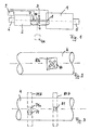
Das in Fig. 1 dargestellte Ausführungsbeispiel der
erfindungsgemässen Schaftwebmaschine umfasst eine
Webmaschine 1 und eine Schaftmaschine 2. Die Webmaschine
1 und die Schaftmaschine 2 sind mittels einer
mechanischen Transmissionsvorrichtung, welche eine
Kupplung 3 umfasst, miteinander koppelbar, sodass sie im
gekoppelten Zustand einen gemeinsamen Antriebsstrang
aufweisen, von dem aus zeichnerischen Gründen nur der
Teil 4 zwischen Webmaschine 1 und Schaftmaschine 2
dargestellt ist. Ferner umfasst die Schaftwebmaschine
einen an der Webmaschine 1 angeordneten Hauptantrieb in
Form eines Motors 5 (üblicherweise ein Elektromotor)
sowie einen an der Schaftmaschine 2 angeordneten
Hilfsantrieb in Form des Motors 6 (üblicherweise
ebenfalls ein Elektromotor). Darüberhinaus umfasst das
gezeigte Ausführungsbeispiel der Schaftwebmaschine noch
Sensoren 7 und 8, die jeweils mittels Signalleitungen mit
einer Regelung 9 verbunden sind. Die Regelung 9
ihrerseits ist mittels einer Signalleitung mit dem Motor
6, also mit dem Hilfsantrieb, verbunden. Schliesslich ist
in Fig. 1 noch optional ein weiterer (Zusatz-)Antrieb ZA
(Kriechgang) vorgesehen, der über ein entsprechendes
Getriebe ZG an den Antriebsstrang ankoppelbar ist und
insbesondere bei der Schussuche zum Einsatz kommen kann,
entweder alleine (dann muss er allerdings so
dimensioniert sein, dass er in der Lage ist, die
Schaftmaschine alleine im Kriechgang anzutreiben) oder
aber zusammen mit dem Motor 6.The embodiment shown in Fig. 1
Dobby loom according to the invention comprises a
Weaving machine 1 and a
Im Betrieb treibt der Motor 5 die Webmaschine 1 und
aufgrund der Kopplung von Webmaschine 1 und
Schaftmaschine 2 auch die Schaftmaschine 2 an. Dabei kann
insbesondere an dem dargestellten Teil 4 des
Antriebsstrangs aufgrund der grossen oszillierenden
massebehafteten Bauteile in der Webmaschine 1 und der
Schaftmaschine 2 ein sehr grosses Drehmoment anliegen,
welches sich zu dem für die Bewegung der Webschäfte
erforderlichen Antriebsmoment addiert. Dieses in diesem
Bereich tatsächlich am Antriebsstrang anliegende
Drehmoment wird entweder nur mittels eines der beiden
Sensoren 7 oder 8 oder aber mittels beider Sensoren
erfasst. Ob das Drehmoment mittels nur einem der Sensoren
7,8 oder aber mittels beider Sensoren 7 und 8 erfasst
wird, hängt davon ab, wie viele Sensoren tatsächlich
vorgesehen sind und vor allem hängt es davon ab, welcher
Typ von Sensor eingesetzt wird. Auf die verschiedenen
Typen von Sensoren wird weiter unten noch genauer
eingegangen. Das Ausgangssignal der Sensoren 7 und 8 wird
mittels Signalleitungen einer Regelung 9 zugeführt,
welche ihrerseits über eine Signalleitung 10 den Motor 6,
also den Hilfsantrieb, ansteuert. Die Ansteuerung des
Motors 6 durch die Regelung 9 erfolgt dabei so, dass
Schwankungen des zwischen der Webmaschine 1 und der
Schaftmaschine 2 anliegenden Drehmoments und/oder
Schwankungen der Drehzahl reduziert werden.In operation, the
Hinsichtlich der Regelung des Drehmoments eignen sich
dabei unterschiedliche Regelstrategien wie
Zur Erläuterung sei ein Fall betrachtet, bei dem die
Webmaschine 1 und die Schaftmaschine 2 eine gegenläufige
Bewegung anstreben, was heisst, dass die eine Maschine
ein in Bezug auf den zunehmenden Drehwinkel zunehmendes
Drehmoment, die andere Maschine hingegen ein in Bezug auf
den zunehmenden Drehwinkel abnehmendes Drehmoment
erfordert (die eine Maschine quasi bremsend, die andere
hingegen treibend wirkt). Dies ruft in der Kupplung 3 und
in dem zwischen Webmaschine 1 und Schaftmaschine 2
angeordneten Teil 4 des Antriebsstrangs ein grosses
Drehmoment hervor. Dieses grosse Drehmoment wird von den
Sensoren 7 und 8 (oder je nach Sensortyp auch nur von
einem der beiden) erfasst und in Form eines elektrischen
Signals an die Regelung 9 weitergeleitet. Die Regelung 9
steuert demzufolge den Hilfsantrieb, also den Motor 6, so
an, dass dieses Drehmoment reduziert wird. Dadurch wird
der Antriebsstrang entlastet, aber auch der Hauptantrieb,
also der Motor 5, der ansonsten dieses Drehmoment alleine
aufbringen müsste (sofern er dazu ausgelegt ist).For explanation, consider a case where the
Weaving machine 1 and the dobby 2 a counter-rotating
Strive for movement, which means that one machine
an increasing in relation to the increasing angle of rotation
Torque, the other machine, however, in terms of
torque decreasing the increasing angle of rotation
requires (one machine practically braking, the other
however, has a driving effect). This calls in
Die erfindungsgemässe Lösung ist aber auch hinsichtlich des gesamten Energieverbrauchs (das ist die aufzuwendende Gesamtleistung, die für die Erzeugung des erforderlichen Drehmoments benötigt wird), günstig. Dies hängt ursächlich mit der mechanischen Kopplung zusammen. Bei einer Schaftwebmaschine mit mechanisch getrennten Antrieben für die Schaftmaschine und die Webmaschine, also ohne Verbindungselemente, müsste die Energie zum Gleichlauf der beiden Maschinen vollständig von den Antrieben der Maschinen bereitgestellt werden (bei gegenläufigen Bewegungstendenzen müsste also ein Antriebsmotor bremsend, der andere hingegen treibend wirken), was mit entsprechenden Umsetzungsverlusten (bei den Motoren) verbunden wäre. Bei einer mechanischen Kopplung hingegen gleichen sich die unterschiedlichen Bewegungstendenzen mindestens teilweise über die mechanische Kopplung von Webmaschine und Schaftmaschine aus (was sich z.B. in einer Torsion äussert). Eine Schaftwebmaschine mit mechanischer Kopplung zwischen Webmaschine und Schaftmaschine ist also in diesem Fall günstiger als eine Schaftwebmaschine ohne mechanische Kopplung. However, the solution according to the invention is also regarding of the total energy consumption (this is the one to be used Total power required for the generation of the Torque is required), cheap. This depends causally related to the mechanical coupling. At a dobby loom with mechanically separated Drives for the dobby and the weaving machine, so without connecting elements, the energy would have to Synchronization of the two machines completely from the Drives of the machines are provided (at opposing movement tendencies would have to be Driving motor braking, the other driving act), which with corresponding implementation losses (at the motors). With a mechanical Coupling, however, are the same Movement tendencies at least partially over the mechanical coupling of loom and dobby from (which manifests itself e.g. in a torsion). A Doom loom with mechanical coupling between So loom and dobby is in this case cheaper than a shaft loom without mechanical Coupling.
Hinsichtlich der Regelung der Drehzahl bieten sich
unterschiedliche Regelstrategien an wie
Beispielhaft sei ein Fall betrachtet, bei dem die
Webmaschine 1 und die Schaftmaschine 2 beide eine
mitläufige Bewegung anstreben, wobei beide Maschinen ein
in Bezug auf den zunehmenden Drehwinkel abnehmendes
Drehmoment erfordern (das heisst, sie tendieren zu einer
höheren Drehzahl hin). Ein entsprechendes Signal wird von
den Sensoren 7 und 8 an die Regelung 9 weitergeleitet.
Die Regelung 9 steuert dann den Motor 6 so an, dass er
bremsend auf den Antriebsstrang wirkt, da sonst die
Drehzahl zunehmen würde (und der Hauptantrieb alleine
bremsend auf den Antriebsstrang wirken müsste).As an example, consider a case in which the
Weaving machine 1 and
Ferner sei beispielhaft ein Fall betrachtet, bei dem die
Webmaschine 1 und die Schaftmaschine 2 ebenfalls eine
mitläufige Bewegung anstreben, allerdings derart, dass
beide Maschinen in Bezug auf den zunehmenden Drehwinkel
ein zunehmendes Drehmoment erfordern (das heisst, sie
tendieren zu einer niedrigeren Drehzahl hin). Ein
entsprechendes Signal wird von den Sensoren 7 und 8 an
die Regelung 9 weitergeleitet. Die Regelung 9 steuert
dann den Motor 6 so an, dass er antreibend auf den
Antriebsstrang wirkt, da sonst die Drehzahl abnehmen
würde bzw. der Hauptantrieb die gesamte Antriebsleistung
aufbringen müsste. Dies würde aber eine höhere Belastung
des Hauptantriebs bedeuten, der das erforderliche
Beschleunigungs-Drehmoment alleine aufbringen müsste. Furthermore, consider a case in which the
Weaving machine 1 and
Natürlich sind auch gemischte Regelstrategien denkbar,
also solche Strategien, bei denen fallweise Schwankungen
des Drehmoments bzw. Schwankungen der Drehzahl geregelt
werden. Beispielweise kann es eine Strategie sein, dass
a) wenn sich das Drehmoment in Bezug auf den zunehmenden
Drehwinkel gleichsinnig ändert, also i.d. Regel ein
kleines Drehmoment zwischen der Webmaschine 1 und der
Schaftmaschine 2 anliegt, die Drehzahl geregelt wird
b) wenn sich das Drehmoment in Bezug auf den zunehmenden
Drehwinkel gegensinnig ändert, also i.d. Regel ein
grosses Drehmoment zwischen der Webmaschine 1 und der
Schaftmaschine 2 anliegt, das Drehmoment geregelt wird,
derart, dass der zwischen Webmaschine 1 und
Schaftmaschine 2 angeordenete Teil des Antriebsstrangs 4
und die Kupplung 3 entlastet werden. Eine derartige
Strategie ist auch bezüglich des Gesamtwirkungsgrads
günstig.Of course, mixed control strategies are also conceivable,
So those strategies where there are fluctuations from case to case
of the torque or fluctuations in the speed regulated
become. For example, it can be a strategy that
a) if the torque is increasing in relation to the
Angle of rotation changes in the same direction, i.e. usually Rule one
small torque between the weaving machine 1 and the
Zur Erfassung des Drehmoments, das zwischen Webmaschine 1
und Schaftmaschine 2 am Antriebsstrang anliegt, kann auf
dem Teil 4 des Antriebsstrangs ein Sensor aufgebracht
sein, der eine Dehnungsmessstreifenanordnung umfasst. Ein
derartiger Sensor ist vom Prinzip her in Fig. 2 gezeigt
(stark vergrössert). Man erkennt dort eine
Dehnungsmessstreifenanordnung 80, die aufgrund einer
Torsion des Teils 4 des Antriebsstrangs, die von dem
anliegenden Drehmoment hervorgerufen ist, aus ihrer
Ruhelage 80a ausgelenkt ist. Die Ruhelage 80a ist dabei
in Fig. 2 strichliert dargestellt. Das Ausgangssignal der
Dehnungsmessstreifenanordnung 80 ist ein Mass für die
Torsion des Teils 4 des Antriebsstrangs und die Torsion
des Teils 4 des Antriebsstrangs ist wiederum ein Mass für
das anliegende Drehmoment. Ist also das anliegende
Drehmoment die einzige zu regelnde Grösse, reicht im
Grunde ein einziger solcher Sensor 80 aus. Es ist
selbstverständlich, dass ein solcher Sensor 80 auch noch
ein geeignetes Übertragungselement aufweist (z.B. einen
geeigneten Transducer, in Fig. 2 aus zeichnerischen
Gründen nicht dargestellt), welches im Betrieb das
Ausgangssignal der Dehnungsmessstreifenanordnung von dem
rotierenden Antriebsstrang zu einem feststehenden
Maschinenteil überträgt.For the detection of the torque between the weaving machine 1
and
Ein anderes Ausführungsbeispiel, welches in Fig. 3
dargestellt ist, weist zwei Sensoren auf, die als
Winkelgeber 71 und 81 ausgebildet und in Längsrichtung
des Antriebsstrangs betrachtet zueinander versetzt
angeordnet sind. Da auch hier der Teil 4 des
Antriebsstrangs aufgrund eines anliegenden Drehmoments
tordiert, ist der Winkelgeber 71 aus seiner Ruhelage 71a,
die strichliert angedeutet ist, ausgelenkt. Um die
Auslenkung festzustellen, benötigt man natürlich
entsprechende Detektoren, die entlang des Umfangs des
Antriebsstrangs angeordnet sind. Dies ist in Fig. 3 durch
die strichlierten Linien 71b und 81b schematisch
angedeutet. Das Mass der Auslenkung im Verhältnis zur
Ruhelage ist ein Mass für die Torsion des Teils 4 des
Antriebsstrangs und diese wiederum ein Mass für das
anliegende Drehmoment. Winkelgeber haben aber auch den
Vorteil, dass mit ihrer Hilfe nicht nur das anliegende
Drehmoment, sondern auch die jeweils aktuelle Drehzahl
festgestellt werden kann.Another exemplary embodiment, which is shown in FIG
is shown, has two sensors, which as
In Fig. 4, Fig. 5 und Fig. 6 sind schliesslich solche
Ausführungsbeispiele dargestellt, bei denen das
anliegende Drehmoment mittels Kraftaufnahme-Sensoren
erfasst wird, die die Kräfte an beim Betrieb
feststehenden Teilen, wie z.B. an Lagern, erfassen. In
Fig. 4 ist dabei ein Winkelgetriebe 14 vorgesehen, wie es
z.B. zwischen der Webmaschine 1 und dem Teil 4 (Fig. 1)
des Antriebsstrangs vorgesehen sein kann. Die beiden
Teile des Antriebsstrangs sind hier nur ausschnittsweise
angedeutet, man erkennt ein Endstück 10 des von der
Webmaschine 1 kommenden Teils des Antriebsstrangs und ein
Endstück 40 des zwischen Webmaschine 1 und Schaftmaschine
2 vorgesehen Teils 4 des Antriebsstrangs. Die beiden
einander zugewandten Endstücke sind in Lagern 11 bzw. 41
geführt und mittels der Kegelzahnräder 12 und 42
mechanisch miteinander gekoppelt. Wird nun eine Kraft
bzw. ein Drehmoment vom Kegelzahnrad 12 auf das
Kegelzahnrad 42 übertragen, so würde der Teil 4 des
Antriebsstrangs ausweichen wollen, wird aber vom Lager 41
daran gehindert. Infolgedessen wirkt eine entsprechende
Kraft auf das Lager 41, welche von einem entsprechenden
Kraftaufnahme-Sensor (siehe Fig. 6) erfasst wird.4, 5 and 6 are finally such
Illustrated embodiments in which the
applied torque by means of force absorption sensors
is recorded, the forces on during operation
fixed parts, e.g. on bearings. In
Fig. 4, an
In Fig. 5 ist ein anderes Getriebe 14a dargestellt, wie
es ebenfalls zwischen der Webmaschine 1 und dem Teil 4
des Antriebsstrangs vorgesehen sein kann. Die beiden
Teile des Antriebsstrangs sind hier nur ausschnittsweise
angedeutet, man erkennt ein Endstück 10a des von der
Webmaschine 1 kommenden Teils des Antriebsstrangs und ein
Endstück 40a des zwischen Webmaschine 1 und
Schaftmaschine 2 vorgesehen Teils 4 des Antriebsstrangs.
Die beiden Endstücke sind wieder in Lagern 11a bzw. 41a
geführt und mittels der radial ineinander greifenden
Zahnräder 12a und 42a mechanisch miteinander gekoppelt.
Wird nun eine Kraft bzw. ein Drehmoment vom Zahnrad 12a
auf das Zahnrad 42a übertragen, so würde der Teil 4 des
Antriebsstrangs ausweichen wollen, wird aber vom Lager
41a daran gehindert. Infolgedessen wirkt eine
entsprechende Kraft auf das Lager 41a, welche von einem
entsprechenden Kraftaufnahme-Sensor (siehe Fig. 6)
erfasst wird, ähnlich wie bei dem anhand von Fig. 4
beschriebenen Ausführungsbeispiel.5 shows another
Fig. 6 zeigt schliesslich schematisch einen Sensor 72,
welcher beispielsweise am Lager 11 bzw. 11a (Fig.4,Fig.5)
vorgesehen sein kann. Wie bereits anhand von Fig. 4 und
Fig. 5 erläutert, wirkt beim Übertragen einer Kraft bzw.
eines Drehmoments auf den Teil 4 des Antriebsstrangs eine
Kraft auf das Lager 41 bzw. 41a, da der Antriebsstrang im
dem Lager geführt ist und nicht ausweichen kann. Dabei
können die auf das Lager 41a wirkende Kräfte in Richtung
der Pfeile F1 und F2 von dem Sensor 72 erfasst und auf
diese Weise die Kraft bzw. das Drehmoment bestimmt
werden, welches die entsprechende Kraft auf das Lager
verursacht hat.6 finally shows schematically a
Die Schaftwebmaschine umfasst eine Webmaschine und eine Schaftmaschine, die über eine mechanische Transmissionsvorrichtung miteinander koppelbar sind und im gekoppelten Zustand einen gemeinsamen Antriebsstrang aufweisen, der von einem Hauptantrieb antreibbar ist. Sie umfasst ferner einen Hilfsantrieb, der zumindest auf den die Schaftmaschine antreibenden Teil des Antriebsstrangs wirkend angeordnet ist. Die Schaftwebmaschine umfasst ferner mindestens ein Sensor, welcher das tatsächlich am Antriebsstrang anliegende Drehmoment erfasst und der im Bereich zwischen der Webmaschine und der Schaftmaschine oder im jeweils an diesen Bereich angrenzenden Endbereich der Webmaschine bzw. der Schaftmaschine entlang des Antriebsstrangs angeordnet ist. Dieser Sensor ist mit einer Regelung verbunden, welche den Hilfsantrieb so ansteuert, dass Schwankungen des zwischen der Webmaschine und der Schaftmaschine anliegenden Drehmoments und/oder Schwankungen der Drehzahl reduziert werden.The dobby weaving machine comprises one weaving machine and one Dobby, which has a mechanical Transmission device can be coupled together and in the coupled state, a common drive train have which can be driven by a main drive. she further includes an auxiliary drive that is at least on the the shaft driving part of the drive train is arranged acting. The dobby loom includes Furthermore, at least one sensor that actually on Drive train applied torque recorded and the in Area between the loom and the dobby or in the end area adjacent to this area the weaving machine or the dobby along the Drive train is arranged. This sensor is with a control connected, so the auxiliary drive controls that fluctuations between the weaving machine and the torque applied to the dobby and / or Fluctuations in the speed can be reduced.
Claims (7)
- Heald loom comprising a weaving machine (1) and a dobby (2) which can be coupled to one another via a mechanical transmission apparatus (3) and have a common drive train in the coupled state which can be driven by a main drive (5), and also comprising an auxiliary drive (6) which is arranged to act at least on the part of the drive train driving the dobby, characterised in that at least one sensor (7, 8) which measures the torque actually present at the drive train is arranged along the drive train in the region between the weaving machine (1) and the dobby (2) or in the end region of the weaving machine (1) or the dobby (2) respectively bordering on this region; and in that this sensor (7, 8) is connected to a control system (9) which actuates the auxiliary drive (6) in such a manner that the torque and/or fluctuations in the speed of rotation present between the weaving machine (1) and the dobby (2) are reduced.
- Heald loom in accordance with claim 1 characterised in that the sensor (7, 8) or parts thereof is/are arranged on the drive train.
- Heald loom in accordance with claim 2 characterised in that the sensor comprises a strain gauge arrangement (80) and a suitable transmission element for the transmission of the signal from the drive train to a part of the machine which is fixed during operation.
- Heald loom in accordance with claim 1 or claim 2 characterised in that at least two sensors are provided which are executed as angle sensors (71, 81) and are arranged to be mutually displaced when viewed in the longitudinal direction of the drive train.
- Heald loom in accordance with claim 1 characterised in that the sensor is executed as a force pick-up sensor (72) and is arranged in such a manner that it measures, at a part (41, 41a) of the heald loom which is fixed during operation, the reaction forces that are produced by the torque which is present.
- Heald loom in accordance with one of the claims 1 to 5 characterised in that it has, in addition to the main drive (5) and the auxiliary drive (6), a further drive (ZA) which can be coupled to the part of the drive train driving the dobby.
- Method for the regulation of a heald loom which comprises a weaving machine (1) and a dobby (2) which can be coupled to one another via a mechanical transmission apparatus (3) and have a common drive train in the coupled state which is driven by a main drive (5) during operation, and which also comprises an auxiliary drive (6) which is arranged to act at least on the part of the drive train driving the dobby, characterised in that the torque actually present at the drive train is measured by at least one sensor (7, 8) which is arranged along the drive train in the region between the weaving machine (1) and the dobby (2), or in the end region of the weaving machine (1) or the dobby (2) respectively bordering on this region, and in that a corresponding signal is supplied to a control system (9) as a result of which the auxiliary drive (6) is actuated in such a manner by the control system (9) that the torque and/or fluctuations in the speed of rotation present between the weaving machine (1) and the dobby (2) are reduced.
Priority Applications (3)
| Application Number | Priority Date | Filing Date | Title |
|---|---|---|---|
| EP97810245A EP0872585B1 (en) | 1997-04-16 | 1997-04-22 | Loom with dobby and method for controlling such a loom |
| US09/059,660 US6186184B1 (en) | 1997-04-16 | 1998-04-13 | Heald loom and a method for regulating a heald loom |
| JP10102704A JPH10325034A (en) | 1997-04-16 | 1998-04-14 | Heald loom and control of heald loom |
Applications Claiming Priority (3)
| Application Number | Priority Date | Filing Date | Title |
|---|---|---|---|
| EP97810234 | 1997-04-16 | ||
| EP97810234 | 1997-04-16 | ||
| EP97810245A EP0872585B1 (en) | 1997-04-16 | 1997-04-22 | Loom with dobby and method for controlling such a loom |
Publications (2)
| Publication Number | Publication Date |
|---|---|
| EP0872585A1 EP0872585A1 (en) | 1998-10-21 |
| EP0872585B1 true EP0872585B1 (en) | 2000-07-19 |
Family
ID=26148018
Family Applications (1)
| Application Number | Title | Priority Date | Filing Date |
|---|---|---|---|
| EP97810245A Expired - Lifetime EP0872585B1 (en) | 1997-04-16 | 1997-04-22 | Loom with dobby and method for controlling such a loom |
Country Status (3)
| Country | Link |
|---|---|
| US (1) | US6186184B1 (en) |
| EP (1) | EP0872585B1 (en) |
| JP (1) | JPH10325034A (en) |
Families Citing this family (7)
| Publication number | Priority date | Publication date | Assignee | Title |
|---|---|---|---|---|
| BE1011560A3 (en) * | 1997-11-21 | 1999-10-05 | Picanol Nv | WEAVING MACHINE AND METHOD FOR CONTROLLING AND / OR STARTING AND / OR STOPPING A DRIVE MOTOR. |
| DE19960928C2 (en) * | 1999-12-17 | 2002-04-25 | Dornier Gmbh Lindauer | Device for establishing a drive connection between a dobby and different shedding machines |
| DE10061717B4 (en) * | 2000-12-12 | 2006-01-26 | Lindauer Dornier Gmbh | Drive arrangement for a weaving machine and shedding machine |
| DE502006006342D1 (en) * | 2006-10-06 | 2010-04-15 | Groz Beckert Kg | Shaft gear for a weaving machine |
| CN101070658B (en) * | 2007-04-29 | 2010-11-17 | 江苏万工科技集团有限公司 | Beating torque automatic adjusting device of air-jet loom |
| EP2226766A3 (en) * | 2009-03-02 | 2014-06-11 | Sikorsky Aircraft Corporation | Rotor system health monitoring using shaft load measurements and virtual monitoring of loads |
| US10501872B2 (en) * | 2015-08-26 | 2019-12-10 | Picanol | Drive mechanism for driving a heald frame of a weaving machine |
Family Cites Families (6)
| Publication number | Priority date | Publication date | Assignee | Title |
|---|---|---|---|---|
| FR2660672B1 (en) * | 1990-04-06 | 1992-08-28 | Staubli Sa Ets | SYSTEM FOR DRIVING A MACHINE FOR FORMING A CROWD ON A WEAVING MACHINE. |
| EP0504105B1 (en) * | 1991-03-13 | 1997-10-15 | DE FRIES, Jan Richard | Electromotive drive system for intermittently working machines with angular displacement dependent variable torque |
| JP3595357B2 (en) * | 1994-06-30 | 2004-12-02 | ファナック株式会社 | Tandem control method using digital servo |
| FR2732698B1 (en) * | 1995-04-05 | 1997-05-23 | Staubli Sa Ets | SYSTEM FOR THE TRAINING OF MECHANICS FOR THE FORMATION OF CROWDS ON WEAVING LOOMS |
| JPH08302545A (en) * | 1995-05-12 | 1996-11-19 | Tsudakoma Corp | Driving mechanism for loom |
| DE59607360D1 (en) * | 1996-04-04 | 2001-08-30 | Sulzer Textil Ag Rueti | Jacquard weaving machine and method for operating the same |
-
1997
- 1997-04-22 EP EP97810245A patent/EP0872585B1/en not_active Expired - Lifetime
-
1998
- 1998-04-13 US US09/059,660 patent/US6186184B1/en not_active Expired - Fee Related
- 1998-04-14 JP JP10102704A patent/JPH10325034A/en not_active Withdrawn
Also Published As
| Publication number | Publication date |
|---|---|
| US6186184B1 (en) | 2001-02-13 |
| EP0872585A1 (en) | 1998-10-21 |
| JPH10325034A (en) | 1998-12-08 |
Similar Documents
| Publication | Publication Date | Title |
|---|---|---|
| WO1999060362A1 (en) | Stress test rig for helicopter transmissions | |
| EP0953073B1 (en) | Drive for a mechanical loom | |
| EP2762438B1 (en) | Process for influencing a winch force acting on a rope drive and device suitable for such a process | |
| EP0726345B1 (en) | Drive mechanism for a loom | |
| EP0872585B1 (en) | Loom with dobby and method for controlling such a loom | |
| EP1763601B1 (en) | Drive for a web machine | |
| EP0799920B1 (en) | Jacquard loom and method of operating said loom | |
| WO2018086925A1 (en) | Drive device for a motor vehicle, corresponding motor vehicle, and method for operating a drive device | |
| WO2008000535A1 (en) | Apparatus for producing vibrations | |
| EP1357309A2 (en) | Method for controlling the starting procedure of a dual clutch transmission | |
| DE102008014531B4 (en) | Method and device for adapting a clutch characteristic | |
| DE19914131A1 (en) | Start-up control for weaving machines, involves storing speed information from previous start-ups and correcting subsequent motor speed settings accordingly | |
| DE102004039273B4 (en) | Dual-clutch transmission and method for controlling or regulating switching operations on a dual-clutch transmission | |
| EP1799898A1 (en) | Reed drive of a loom | |
| EP4295062A1 (en) | Variable-speed transmission with shift drum driven by an electric motor, and method for controlling such a variable-speed transmission | |
| DE102008046846A1 (en) | Internal combustion engine controlling method for drive train of motor vehicle, involves actuating engine for preparation of starting/stopping processes, such that reverse movement is reproached to stabilize number of revolutions of engine | |
| EP3710299B1 (en) | Method for determining clutch parameters of an automatic transmission having at least one clutch | |
| DE102007008613B4 (en) | Driving device and method for driving a vehicle | |
| DE102017201753A1 (en) | Method and control device for detecting the switching position of a positive switching element of a transmission | |
| DE128980T1 (en) | DRIVE GEARBOX FOR MACHINES. | |
| DE102017221224B3 (en) | Device and method for producing tissue with a loom and two Jacquard machines | |
| DE102014016450B3 (en) | Method for operating a multi-axle drive train for a motor vehicle and corresponding multi-axis drive train | |
| DE19535333B4 (en) | Drive device for a double carpet weaving machine | |
| WO2018041549A1 (en) | Drive arrangement for a ship with means for state monitoring | |
| EP3300578B1 (en) | Method for controlling an agricultural machine |
Legal Events
| Date | Code | Title | Description |
|---|---|---|---|
| PUAI | Public reference made under article 153(3) epc to a published international application that has entered the european phase |
Free format text: ORIGINAL CODE: 0009012 |
|
| AK | Designated contracting states |
Kind code of ref document: A1 Designated state(s): BE CH DE GB IT LI SE |
|
| AX | Request for extension of the european patent |
Free format text: AL;LT;LV;RO;SI |
|
| 17P | Request for examination filed |
Effective date: 19990324 |
|
| AKX | Designation fees paid |
Free format text: BE CH DE GB IT LI SE |
|
| GRAG | Despatch of communication of intention to grant |
Free format text: ORIGINAL CODE: EPIDOS AGRA |
|
| 17Q | First examination report despatched |
Effective date: 19990706 |
|
| RAP1 | Party data changed (applicant data changed or rights of an application transferred) |
Owner name: SULZER TEXTIL AG |
|
| GRAG | Despatch of communication of intention to grant |
Free format text: ORIGINAL CODE: EPIDOS AGRA |
|
| GRAH | Despatch of communication of intention to grant a patent |
Free format text: ORIGINAL CODE: EPIDOS IGRA |
|
| GRAH | Despatch of communication of intention to grant a patent |
Free format text: ORIGINAL CODE: EPIDOS IGRA |
|
| GRAA | (expected) grant |
Free format text: ORIGINAL CODE: 0009210 |
|
| AK | Designated contracting states |
Kind code of ref document: B1 Designated state(s): BE CH DE GB IT LI SE |
|
| REG | Reference to a national code |
Ref country code: CH Ref legal event code: NV Representative=s name: SULZER MANAGEMENT AG Ref country code: CH Ref legal event code: EP |
|
| GBT | Gb: translation of ep patent filed (gb section 77(6)(a)/1977) |
Effective date: 20000719 |
|
| REF | Corresponds to: |
Ref document number: 59702052 Country of ref document: DE Date of ref document: 20000824 |
|
| ITF | It: translation for a ep patent filed |
Owner name: ING. ZINI MARANESI & C. S.R.L. |
|
| EN | Fr: translation not filed | ||
| PLBE | No opposition filed within time limit |
Free format text: ORIGINAL CODE: 0009261 |
|
| STAA | Information on the status of an ep patent application or granted ep patent |
Free format text: STATUS: NO OPPOSITION FILED WITHIN TIME LIMIT |
|
| 26N | No opposition filed | ||
| REG | Reference to a national code |
Ref country code: GB Ref legal event code: IF02 |
|
| PGFP | Annual fee paid to national office [announced via postgrant information from national office to epo] |
Ref country code: CH Payment date: 20020319 Year of fee payment: 6 |
|
| PGFP | Annual fee paid to national office [announced via postgrant information from national office to epo] |
Ref country code: SE Payment date: 20020327 Year of fee payment: 6 |
|
| PGFP | Annual fee paid to national office [announced via postgrant information from national office to epo] |
Ref country code: GB Payment date: 20020402 Year of fee payment: 6 |
|
| PG25 | Lapsed in a contracting state [announced via postgrant information from national office to epo] |
Ref country code: GB Free format text: LAPSE BECAUSE OF NON-PAYMENT OF DUE FEES Effective date: 20030422 |
|
| PG25 | Lapsed in a contracting state [announced via postgrant information from national office to epo] |
Ref country code: SE Free format text: LAPSE BECAUSE OF NON-PAYMENT OF DUE FEES Effective date: 20030423 |
|
| PG25 | Lapsed in a contracting state [announced via postgrant information from national office to epo] |
Ref country code: LI Free format text: LAPSE BECAUSE OF NON-PAYMENT OF DUE FEES Effective date: 20030430 Ref country code: CH Free format text: LAPSE BECAUSE OF NON-PAYMENT OF DUE FEES Effective date: 20030430 |
|
| EUG | Se: european patent has lapsed | ||
| GBPC | Gb: european patent ceased through non-payment of renewal fee |
Effective date: 20030422 |
|
| REG | Reference to a national code |
Ref country code: CH Ref legal event code: PL |
|
| PGFP | Annual fee paid to national office [announced via postgrant information from national office to epo] |
Ref country code: DE Payment date: 20050418 Year of fee payment: 9 |
|
| PGFP | Annual fee paid to national office [announced via postgrant information from national office to epo] |
Ref country code: BE Payment date: 20050509 Year of fee payment: 9 |
|
| PG25 | Lapsed in a contracting state [announced via postgrant information from national office to epo] |
Ref country code: BE Free format text: LAPSE BECAUSE OF NON-PAYMENT OF DUE FEES Effective date: 20060430 |
|
| PGFP | Annual fee paid to national office [announced via postgrant information from national office to epo] |
Ref country code: IT Payment date: 20060430 Year of fee payment: 10 |
|
| PG25 | Lapsed in a contracting state [announced via postgrant information from national office to epo] |
Ref country code: DE Free format text: LAPSE BECAUSE OF NON-PAYMENT OF DUE FEES Effective date: 20061101 |
|
| BERE | Be: lapsed |
Owner name: *SULZER TEXTIL A.G. Effective date: 20060430 |
|
| PG25 | Lapsed in a contracting state [announced via postgrant information from national office to epo] |
Ref country code: IT Free format text: LAPSE BECAUSE OF NON-PAYMENT OF DUE FEES Effective date: 20070422 |