EP0872002B1 - Low-voltage switch system for supplying or distributing electric power - Google Patents
Low-voltage switch system for supplying or distributing electric power Download PDFInfo
- Publication number
- EP0872002B1 EP0872002B1 EP96907264A EP96907264A EP0872002B1 EP 0872002 B1 EP0872002 B1 EP 0872002B1 EP 96907264 A EP96907264 A EP 96907264A EP 96907264 A EP96907264 A EP 96907264A EP 0872002 B1 EP0872002 B1 EP 0872002B1
- Authority
- EP
- European Patent Office
- Prior art keywords
- low
- voltage switchgear
- switchgear assembly
- mentioned
- slide
- Prior art date
- Legal status (The legal status is an assumption and is not a legal conclusion. Google has not performed a legal analysis and makes no representation as to the accuracy of the status listed.)
- Expired - Lifetime
Links
- 239000000463 material Substances 0.000 claims abstract description 4
- 239000002184 metal Substances 0.000 claims description 5
- 238000005192 partition Methods 0.000 claims description 2
- 210000001331 nose Anatomy 0.000 claims 1
- 238000000926 separation method Methods 0.000 claims 1
- 238000009434 installation Methods 0.000 abstract 1
- 238000013459 approach Methods 0.000 description 3
- 238000005253 cladding Methods 0.000 description 1
- 238000011161 development Methods 0.000 description 1
- 230000018109 developmental process Effects 0.000 description 1
- 238000003780 insertion Methods 0.000 description 1
- 230000037431 insertion Effects 0.000 description 1
- 238000004519 manufacturing process Methods 0.000 description 1
- 125000006850 spacer group Chemical group 0.000 description 1
Images


Classifications
-
- H—ELECTRICITY
- H02—GENERATION; CONVERSION OR DISTRIBUTION OF ELECTRIC POWER
- H02B—BOARDS, SUBSTATIONS OR SWITCHING ARRANGEMENTS FOR THE SUPPLY OR DISTRIBUTION OF ELECTRIC POWER
- H02B1/00—Frameworks, boards, panels, desks, casings; Details of substations or switching arrangements
- H02B1/26—Casings; Parts thereof or accessories therefor
- H02B1/30—Cabinet-type casings; Parts thereof or accessories therefor
- H02B1/32—Mounting of devices therein
- H02B1/34—Racks
- H02B1/36—Racks with withdrawable units
Definitions
- the invention relates to a low-voltage switchgear the preamble of claim 1.
- switchgear in power distribution consisting of switchgear in switch cabinets or Device groups, also known as motor, energy or MCC distributors, to protect systems and motors for a long time known and proven.
- the delivery and distribution of electrical energy is included common busbars via interchangeable devices or Device groups reached, these device groups switching and Protection components included and with plug-in contacts on the Grip busbars.
- the device groups are at least for distributors of this type partially pluggable, with at least the load current tap by means of plug contacts that reach over the busbars he follows.
- the load current outlet and the control current connection or The like can either be plugged in or fixed be wired.
- the switching and protection components can include circuit breakers, Motor protection switches, contactors and combinations of these Components such as a turn, star-triangle combination or the like.
- Such an energy distributor is known from DE-A1 42 10 679 become known, the one running parallel to the direction of insertion Has cross struts, the guide means for the inserts have, the guide means as step-shaped or Z-shaped Guide pieces in one piece from the material are pushed out.
- the guide means are relatively inexpensive if that Field busbar system, however, from a compact unit then there are additional cross struts for the guide required.
- EP 0 186 556 describes a field busbar system with a Rail channel shown and described, with the inserts on the pages are arranged.
- the rail system forms one compact unit that fits in any metal cabinet can be arranged. A guide of the inserts in this However, there is no sense.
- WO 93/18564 also includes an energy distributor Wall elements arranged guide slots shown and described, which is structurally complex.
- the object of the invention is therefore a low-voltage switchgear to create according to the preamble of claim 1, the with little design effort with a guide of Device groups is provided, the field busbar system equipped as a compact unit and thus in one any control cabinet is to be accommodated.
- the distribution panel 11 of the low-voltage switchgear shown in FIG. 1 consists essentially of a metal housing, i.e. a frame 12, cladding elements and one Control cabinet door 13.
- the distribution panel 11 also consists of one arranged above and parallel to the ceiling level Main busbar system 14, one perpendicular to the floor plane arranged field busbar system 15 with a rail channel 3 and inserts 4, which are shown in more detail in FIGS. 8 and 9 are.
- the switchgear or located on the slots 4 Device groups of switching devices, such as circuit breakers, Motor protection switches, contactors or the like, engage by means of Load current plug 16 on the field busbars 17.
- the slots 4 have parallel to the floor level Leading edges 5, which between the guide approaches 1 retracted slot 4, as can be seen from FIG. 5 is.
- the guide lugs 1 are on the inside of Side legs of the essentially U-shaped rail channel 3 arranged, the slots 4 between the side legs being held.
- the rail channel 3 consists of a trough-shaped rail channel part 18, the shape of which can be clearly seen in FIG. 7. Furthermore, the rail channel 3 consists of a bulkhead 9 for covering the field busbars 17.
- the bulkhead 9 fastened in the rail channel 3 between the side legs 2 is provided with openings 10 for the load current plug 16, the bulkhead 9 consisting of a sheet metal section.
- the side legs 2 terminate approximately with the slide-in mounting plate 11a, 11b.
- the rail channel 3 is provided with two sections 8 angled on the side legs 2 parallel to the rear wall plane.
- An L-shaped profile rail 19 is used to ground the inserts 4 arranged directly on the bulkhead plate 9, the slots have a laterally arranged ground contact 20.
- the guide lugs 1 are made of the material of the side legs 2 of the rail channel punched out and as above and below the leading edge 5 of the insert Guide lugs provided, these being pushed out at an angle are, preferably at an angle (w) of about 30 to 40 Degrees.
- the guide lugs 1 are approximately triangular. This have a one-piece molded on the side leg 2 Base leg 6 and one as a base for the insert serving corner 7.
- a spacer 21 is in shape a U or C-shaped mounting plate on the Insert mounting plate lla, llb arranged.
- the crossbeams 22, which are shown in FIGS. 1 and 2, are also provided for fastening the rail channel 3.
Landscapes
- Engineering & Computer Science (AREA)
- Power Engineering (AREA)
- Patch Boards (AREA)
- Emergency Protection Circuit Devices (AREA)
- Control Of El Displays (AREA)
- Control Of Indicators Other Than Cathode Ray Tubes (AREA)
- Control Of Eletrric Generators (AREA)
- Gas-Insulated Switchgears (AREA)
- Driving Mechanisms And Operating Circuits Of Arc-Extinguishing High-Tension Switches (AREA)
Abstract
Description
Die Erfindung betrifft eine Niederspannungs-Schaltanlage nach dem Oberbegriff des Anspruches 1.The invention relates to a low-voltage switchgear the preamble of claim 1.
In der Energieverteilung sind Niederspannungs-Schaltanlagen bestehend aus in Schaltschränken befindlichen Schaltgeräten oder Gerätegruppen, auch bekannt als Motor-, Energie- oder MCC-Verteiler, zum Schutz von Anlagen und Motoren seit langem bekannt und bewährt.There are low-voltage switchgear in power distribution consisting of switchgear in switch cabinets or Device groups, also known as motor, energy or MCC distributors, to protect systems and motors for a long time known and proven.
Die Abgabe und Verteilung der elektrischen Energie wird mit gemeinsamen Stromsammelschienen über austauschbare Geräte oder Gerätegruppen erreicht, wobei diese Gerätegruppen Schalt- und Schutzkomponenten enthalten und mit Steckkonktaten auf die Stromsammelschienen greifen.The delivery and distribution of electrical energy is included common busbars via interchangeable devices or Device groups reached, these device groups switching and Protection components included and with plug-in contacts on the Grip busbars.
Die Gerätegruppen sind bei Verteilern dieser Art mindestens teilweise Steckbar, wobei mindestens der Laststromabgriff mittels auf die Stromsammelschienen greifender Steckkontakte erfolgt.The device groups are at least for distributors of this type partially pluggable, with at least the load current tap by means of plug contacts that reach over the busbars he follows.
Der Laststromabgang und die Steuerstromverbindung oder dergleichen können entweder steckbar oder aber auch fest verdrahtet sein.The load current outlet and the control current connection or The like can either be plugged in or fixed be wired.
Die Schalt- und Schutzkomponenten können Leistungsschalter, Motorschutzschalter, Schütze und Kombinationen dieser Komponenten, wie z.B. eine Wende-, Stern-Dreieck-Kombination oder dergleichen sein.The switching and protection components can include circuit breakers, Motor protection switches, contactors and combinations of these Components such as a turn, star-triangle combination or the like.
Aus der DE-A1 42 10 679 ist ein derartiger Energieverteiler bekannt geworden, das parallel zur Einschubrichtung verlaufende Querstreben aufweist, die Führungsmittel für die Einschübe aufweisen, wobei die Führungsmittel als stufenförmige oder Z-förmige Führungsansätze einstückig aus dem Material herausgedrückt sind.Such an energy distributor is known from DE-A1 42 10 679 become known, the one running parallel to the direction of insertion Has cross struts, the guide means for the inserts have, the guide means as step-shaped or Z-shaped Guide pieces in one piece from the material are pushed out.
Die Führungsmittel sind zwar relativ kostengünstig, wenn das Feldsammelschienensystem jedoch aus einer kompakten Einheit bestehen soll, dann sind zusätzlich Querstreben für die Führung erforderlich.The guide means are relatively inexpensive if that Field busbar system, however, from a compact unit then there are additional cross struts for the guide required.
In der EP 0 186 556 ist ein Feldsammelschienensystem mit einem
Schienenkanal gezeigt und beschrieben, wobei die Einschübe an
den Seiten angeordnet sind. Das Schienensystem bildet eine
kompakte Einheit, die in einem beliebigen Metallschrank
angeordnet werden kann. Eine Führung der Einschübe in diesem
Sinne ist jedoch nicht vorhanden.
Ferner ist in der WO 93/18564 ein Energieverteiler mit an Wandelementen angeordneten Führungsschlitzen gezeigt und beschrieben, der jedoch konstruktiv aufwendig ist.WO 93/18564 also includes an energy distributor Wall elements arranged guide slots shown and described, which is structurally complex.
Aufgabe der Erfindung ist es deshalb, eine Niederspannungs-Schaltanlage nach dem Oberbegriff des Anspruches 1 zu schaffen, die bei geringem konstruktiven Aufwand mit einer Führung der Gerätegruppen versehen ist, wobei das Feldsammelschienensystem als eine kompakte Einheit ausgestattet und somit in einem beliebigen Schaltschrank unterzubringen ist.The object of the invention is therefore a low-voltage switchgear to create according to the preamble of claim 1, the with little design effort with a guide of Device groups is provided, the field busbar system equipped as a compact unit and thus in one any control cabinet is to be accommodated.
Die Aufgabe der Erfindung wird durch die kennzeichnenden Merkmale des Anspruches 1 gelöst, während in den Unteransprüchen besonders vorteilhafte Weiterbildungen der Erfindung gekennzeichnet sind.The object of the invention is characterized by the Features of claim 1 solved while in the subclaims particularly advantageous developments of the invention Marked are.
Durch die kennzeichnenden Merkmale des Anspruches 1 kann ein Einschubverteiler mit relativ hoher Bedienfreundlichkeit zu relativ geringen Herstellungskosten geschaffen werden.Due to the characterizing features of claim 1 a Plug-in distributors with relatively high user friendliness relatively low manufacturing costs can be created.
Anhand der Zeichnung, in der bevorzugte Ausführungsbeispiele dargestellt sind, sollen die Erfindung, weitere Ausgestaltungen und Verbesserungen der Erfindung und weitere Vorteile näher beschrieben und erläutert werden.Using the drawing, in the preferred embodiments are shown, the invention, further refinements and improvements of the invention and other advantages be described and explained.
Es zeigt:
- Fig. 1
- eine perspektivische Darstellung eines Verteilerfeldes,
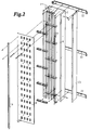
- Fig. 2
- eine auseinandergezogene, perspektivische Darstellung des Feldsammelschienensystems,
- Fig. 3
- eine Seitenansicht eines Seitenschenkels des Schienenkanals,
- Fig. 4
- eine Einzelheitdarstellung der Führungsnasen von vorne,
- Fig. 5
- eine Einzelheitdarstellung der Führungsnasen von der Seite,
- Fig. 6
- eine zweidimensionale Darstellung des wannenförmigen Schienenkanalteiles von vorne,
- Fig. 7
- eine zweidimensionale Darstellung des wannenförmigen Schienenkanalteiles von oben,
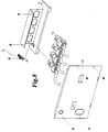
- Fig. 8
- eine auseinandergezogene, perspektivische Darstellung des Einschubes und
- Fig. 9
- eine perspektivische Darstellung des Einschubes.
- Fig. 1
- a perspective view of a distribution field,
- Fig. 2
- an exploded, perspective view of the field busbar system,
- Fig. 3
- a side view of a side leg of the rail channel,
- Fig. 4
- a detailed representation of the guide lugs from the front,
- Fig. 5
- a detailed representation of the guide lugs from the side,
- Fig. 6
- a two-dimensional representation of the trough-shaped rail channel part from the front,
- Fig. 7
- a two-dimensional representation of the trough-shaped rail channel part from above,
- Fig. 8
- an exploded, perspective view of the insert and
- Fig. 9
- a perspective view of the insert.
Das in Fig. 1 gezeigte Verteilerfeld 11 der Niederspannungs-Schaltanlage
besteht im wesentlichen aus einem Metallgehäuse,
d.h. einem Rahmengestell 12, Verkleidungselementen und einer
Schaltschranktür 13. Weiterhin besteht das Verteilerfeld 11 aus
einem oben und parallel zur Deckenebene angeordneten
Hauptsammelschienensystem 14, einem senkrecht zur Bodenebene
angeordneten Feldsammelschienensystem 15 mit einem Schienenkanal
3 und Einschübe 4, die näher in den Figuren 8 und 9 gezeigt
sind.The
Die an den Einschüben 4 befindlichen Schaltgeräte oder
Gerätegruppen von Schaltgeräten, wie Leistungsschalter,
Motorschutzschalter, Schütze oder dergleichen, greifen mittels
Laststromstecker 16 auf die Feldsammelschienen 17.The switchgear or located on the
Die Einschübe 4 weisen parallel zur Bodenebene verlaufende
Führungskanten 5 auf, die zwischen den Führungsansätzen 1 bei
eingefahrenem Einschub 4 liegen, wie anhand der Fig. 5 zu sehen
ist. Die Führungsansätze 1 sind an der Innenseite von
Seitenschenkeln des im wesentlichen U-förmigen Schienenkanals 3
angeordnet, wobei die Einschübe 4 zwischen den Seitenschenkeln
gehalten werden.The
Der Schienenkanal 3 besteht aus einem wannenförmigen
Schienenkanalteil 18, dessen Form in Fig. 7 gut zu sehen ist.
Weiterhin besteht der Schienenkanal 3 aus einer Schottwand 9 zur
Abdeckung der Feldsammelschienen 17.
Die in dem Schienenkanal 3 zwischen den Seitenschenkeln 2
befestigte Schottwand 9 ist mit Öffnungen 10 für die
Laststromstecker 16 versehen, wobei die Schottwand 9 aus einem
Blechabschnitt besteht.
Die Seitenschenkel 2 schließen etwa mit der
Einschubmontageplatte 11a, 11b ab.
Zur Versteifung und Verschraubung des Einschubes 4 mit Schrauben
25 ist der Schienenkanal 3 mit zwei an den Seitenschenkeln 2
parallel zur Rückwandebene abgewinkelten Abschnitten 8 versehen. The
The
The side legs 2 terminate approximately with the slide-in
For stiffening and screwing the
Zur Erdung der Einschübe 4 ist eine L-förmige Profilschiene 19
direkt auf der Schottplatte 9 angeordnet, wobei die Einschübe
einen seitlich angeordneten Erdungskontakt 20 aufweisen.An L-shaped profile rail 19 is used to ground the
Die Führungsansätze 1 sind aus dem Material der Seitenschenkel
2 des Schienenkanals herausgestanzt und als oberhalb und
unterhalb der Führungskante 5 des Einschubes greifende
Führungsnasen vorgesehen, wobei diese schräg herausgedrückt
sind, vorzugsweise unter einen Winkel (w) von etwa 30 bis 40
Winkelgrade.The guide lugs 1 are made of the material of the side legs
2 of the rail channel punched out and as above and
below the leading
Wie Fig. 4 zeigt bestehen die Führungsansätze 1 aus drei
Führungsansätzen 1 jeweils für eine Führungsseite, wobei die
oberhalb und unterhalb der Führungskante 5 des Einschubes 4
liegenden Führungsansätze 1 gegeneinander versetzt angeordnet
sind.4 shows the guide approaches 1 consist of three
Management approaches 1 each for a management side, the
above and below the
Wie Fig.3 zeigt sind fünfzehn untereinanderliegende Führungsebenen vorhanden, wobei ein Einschub durchaus mehrere Führungsebenen in Anspruch nehmen kann, wie anhand der Größenunterschiede der in der Figuren 8 und 9 gezeigten Einschübe deutlich wird.As Fig.3 shows fifteen are one below the other Management levels available, with one bay quite several Management levels can take up, as with the Size differences of those shown in Figures 8 and 9 Inserts becomes clear.
Weiterhin sind die Führungsansätze 1 etwa dreieckförmig. Diese
weisen einen an der Seitenschenkel 2 einstückig angeformten
Grundschenkel 6 und eine als Stützpunkt für den Einschub
dienende Ecke 7 auf.Furthermore, the guide lugs 1 are approximately triangular. This
have a one-piece molded on the side leg 2
Base leg 6 and one as a base for the
Ferner ist, wie Fig. 9 zeigt, ein Abstandselement 21 in Form
einer U- oder C-förmigen Montageplatte auf der
Einschubmontageplatte lla, llb angeordnet.Furthermore, as shown in FIG. 9, a
Zur Abtrennung des Geräteraumes und des Kundenanschlußraumes ist
eine parallel zu den Seitenschenkeln 2 angeordnete Trennwand 23
vorhanden, die an mehreren mit dem Rahmengestell 12 befestigten
Querträgern 22 festgelegt wird.To separate the equipment room and the customer connection room
a
Die Querträger 22, die in den Figuren 1 und 2.dargestellt sind,
sind auch für die Befestigung des Schienenkanals 3 vorgesehen.The
Claims (15)
- Low-voltage switchgear assembly for the delivery or distribution of electrical energy with switching devices or groups of switching devices such as power switches, motor protection switches, contactors, or similar devices located in slide-in units (4), presenting a guidance in the switch cabinet, and being provided with a cabinet-shaped metal casing (12) and with at least one switch-cabinet door (13), while at least the electrical connection between the collecting bus bars and the switching devices is pluggable, while the guiding projections (1) are punched out, and while the slide-in units (4) present guiding edges (5) which run in parallel to the bottom plane, and while the collecting bus bars are field bus bars (17) connected to main bus bars, characterized in that the guiding projections (1) are arranged at the inside of lateral legs (2) of a U-shaped bar channel (3), while the slide-in units (4) are held between the lateral legs, and in that the guiding projections (1) are punched out of the material of the lateral legs (2) of the bar channel.
- Low-voltage switchgear assembly as claimed in claim 1, characterized in that the guiding projections (1) are provided as guide noses engaging above and below the guiding edge (5) of the slide-in unit.
- Low-voltage switchgear assembly as claimed in claim 1 or 2, characterized in that the guiding projections (1) consist of at least three guiding projections (1) for one guiding side, while the guiding projections (1) arranged above and below the guiding edge (5) of the slide-in unit (4) are arranged in an offset position with regard to one another.
- Low-voltage switchgear assembly as claimed in any of the above-mentioned claims, characterized in that the guiding projections (1) are approximately triangular in shape, and consist of a base leg (6) formed integral with the lateral leg (2), and present a corner (7) which serves as a supporting point for the slide-in unit.
- Low-voltage switchgear assembly as claimed in any of the above-mentioned claims, characterized in that the guiding projections (1) are pressed out in an oblique way.
- Low-voltage switchgear assembly as claimed in any of the above-mentioned claims, characterized in that the guiding projections (1) are pressed out at an angle (w) of approximately 30 to 40 angular degrees.
- Low-voltage switchgear assembly as claimed in any of the above-mentioned claims, characterized in that the field bus bars (17) are located vertically with regard to the bottom plane and side by side at the rear wall.
- Low-voltage switchgear assembly as claimed in any of the above-mentioned claims, characterized in that the bar channel (3) presents two angular sections (8) presenting an angle at the lateral legs (2) in parallel to the plane of the rear wall.
- Low-voltage switchgear assembly as claimed in any of the above-mentioned claims, characterized in that a bulkhead panel (9) with openings (10) made of a sheet-metal section is located in the bar channel (3) and fixed between the lateral legs (2).
- Low-voltage switchgear assembly as claimed in any of the above-mentioned claims, characterized in that the lateral legs (2) end approximately at the same place as the slide-in mounting plate (11a, 11b).
- Low-voltage switchgear assembly as claimed in any of the above-mentioned claims, characterized in that an L-shaped sectional bar (19) is located directly on the a bulkhead plate (9) for the earthing/grounding of the slide-in units (4), while the slide-in units (4) present an earthing/grounding contact (20) which is located laterally.
- Low-voltage switchgear assembly as claimed in any of the above-mentioned claims, characterized in that a spacing element (21) formed like a U-shaped or C-shaped mounting plate is located on one slide-in mounting plate (11a, 11b).
- Low-voltage switchgear assembly as claimed in any of the above-mentioned claims, characterized in that it is provided for a 2500 Amperes current rating.
- Low-voltage switchgear assembly as claimed in any of the above-mentioned claims, characterized in that a partition wall (23) is arranged in parallel to the lateral legs (2), and secured at several transverse supports (22) fixed with a mounting frame (12) in order to allow separation into a device compartment, and a compartment for client connections.
- Low-voltage switchgear assembly as claimed in any of the above-mentioned claims, characterized in that the bar channel (3) is secured at several transverse supports (22) fixed with a mounting frame (12).
Applications Claiming Priority (3)
| Application Number | Priority Date | Filing Date | Title |
|---|---|---|---|
| DE19511347A DE19511347A1 (en) | 1995-03-28 | 1995-03-28 | Low-voltage switchgear for the supply or distribution of electrical energy |
| DE19511347 | 1995-03-28 | ||
| PCT/DE1996/000508 WO1996030982A1 (en) | 1995-03-28 | 1996-03-23 | Low-voltage switch system for supplying or distributing electric power |
Publications (2)
| Publication Number | Publication Date |
|---|---|
| EP0872002A1 EP0872002A1 (en) | 1998-10-21 |
| EP0872002B1 true EP0872002B1 (en) | 1999-08-04 |
Family
ID=7757957
Family Applications (1)
| Application Number | Title | Priority Date | Filing Date |
|---|---|---|---|
| EP96907264A Expired - Lifetime EP0872002B1 (en) | 1995-03-28 | 1996-03-23 | Low-voltage switch system for supplying or distributing electric power |
Country Status (9)
| Country | Link |
|---|---|
| EP (1) | EP0872002B1 (en) |
| JP (1) | JPH11502696A (en) |
| AT (1) | ATE183029T1 (en) |
| AU (1) | AU5099096A (en) |
| CA (1) | CA2216638A1 (en) |
| DE (2) | DE19511347A1 (en) |
| ES (1) | ES2139344T3 (en) |
| PL (1) | PL180225B1 (en) |
| WO (1) | WO1996030982A1 (en) |
Families Citing this family (5)
| Publication number | Priority date | Publication date | Assignee | Title |
|---|---|---|---|---|
| DE29719479U1 (en) * | 1997-11-05 | 1999-04-01 | ELEK GmbH, 41470 Neuss | Connection device |
| WO2003036772A1 (en) * | 2001-10-25 | 2003-05-01 | Mitsubishi Denki Kabushiki Kaisha | Control center |
| WO2003038961A1 (en) * | 2001-10-30 | 2003-05-08 | Mitsubishi Denki Kabushiki Kaisha | Power distributor and control center |
| DE102012110247A1 (en) * | 2012-10-26 | 2014-04-30 | Eaton Industries (Austria) Gmbh | Switch cabinet with improved possibility for stringing together |
| JP2019102544A (en) * | 2017-11-29 | 2019-06-24 | 河村電器産業株式会社 | Rack row power supply system |
Family Cites Families (2)
| Publication number | Priority date | Publication date | Assignee | Title |
|---|---|---|---|---|
| US3142003A (en) * | 1961-09-13 | 1964-07-21 | Gen Electric | Electrical control panel structure |
| US5225962A (en) * | 1992-03-11 | 1993-07-06 | Square D Company | Distribution board with rear electrical access |
-
1995
- 1995-03-28 DE DE19511347A patent/DE19511347A1/en not_active Withdrawn
-
1996
- 1996-03-23 ES ES96907264T patent/ES2139344T3/en not_active Expired - Lifetime
- 1996-03-23 PL PL96322548A patent/PL180225B1/en not_active IP Right Cessation
- 1996-03-23 CA CA002216638A patent/CA2216638A1/en not_active Abandoned
- 1996-03-23 AT AT96907264T patent/ATE183029T1/en not_active IP Right Cessation
- 1996-03-23 EP EP96907264A patent/EP0872002B1/en not_active Expired - Lifetime
- 1996-03-23 JP JP8528770A patent/JPH11502696A/en not_active Abandoned
- 1996-03-23 AU AU50990/96A patent/AU5099096A/en not_active Abandoned
- 1996-03-23 WO PCT/DE1996/000508 patent/WO1996030982A1/en not_active Ceased
- 1996-03-23 DE DE59602671T patent/DE59602671D1/en not_active Expired - Fee Related
Also Published As
| Publication number | Publication date |
|---|---|
| EP0872002A1 (en) | 1998-10-21 |
| JPH11502696A (en) | 1999-03-02 |
| DE59602671D1 (en) | 1999-09-09 |
| ATE183029T1 (en) | 1999-08-15 |
| WO1996030982A1 (en) | 1996-10-03 |
| CA2216638A1 (en) | 1996-10-03 |
| ES2139344T3 (en) | 2000-02-01 |
| AU5099096A (en) | 1996-10-16 |
| DE19511347A1 (en) | 1996-10-02 |
| PL322548A1 (en) | 1998-02-02 |
| PL180225B1 (en) | 2001-01-31 |
Similar Documents
| Publication | Publication Date | Title |
|---|---|---|
| EP0872000B1 (en) | Busbar channel system of a low-voltage switch equipment | |
| CH677297A5 (en) | Plug-in voltage surge arrester with overvoltage protector | |
| US5905631A (en) | Low-voltage switchgear assembly for the output or distribution of electrical energy | |
| EP1008215B1 (en) | Power engineering distribution system with a plug-in unit | |
| DE4013223C2 (en) | Power supply terminal | |
| DE3045358C2 (en) | ||
| EP0872002B1 (en) | Low-voltage switch system for supplying or distributing electric power | |
| EP0109568B1 (en) | Cabinet or frame for holding electrical installation drawers | |
| DE19523592C2 (en) | Low-voltage switchgear and controlgear assembly | |
| DE29505243U1 (en) | Earthing device for a slide-in of an energy distribution cabinet | |
| DE4210657C2 (en) | Plug-in low-voltage switchgear for the supply or distribution of electrical energy | |
| DE3878187T2 (en) | MODULAR ELECTRICAL LOW VOLTAGE CONTROL PANEL FOR A MODULAR ELECTRICAL DEVICE. | |
| DE4210679A1 (en) | Plug-in low-voltage switchgear for the supply or distribution of electrical energy | |
| EP3200293A1 (en) | Assembly of an electrical connecting block and a stationary receptacle for this | |
| DE102014114938B4 (en) | Meter location with a mounting device for additional meter devices | |
| DE10205101B4 (en) | Power supply module | |
| DE102004054173B4 (en) | Low voltage switch cabinet | |
| EP1251612B1 (en) | Connection device for a withdrawable unit from a low-voltage board | |
| EP1251613B1 (en) | Connection device for electric board with withdrawable units | |
| DE9204389U1 (en) | Withdrawable low-voltage switchgear for supplying or distributing electrical energy | |
| DE29514997U1 (en) | Fastening board for command, signaling and display devices for low-voltage switchgear for the distribution of electrical energy | |
| WO1996015569A1 (en) | Device for connecting electrical-installation apparatuses | |
| DE102018132273A1 (en) | Device for providing a counter space for an electronic counter in a meter cabinet and meter cabinet containing such a device. | |
| DE69310590T2 (en) | Control panel for low-voltage three-phase meters | |
| DE19713948A1 (en) | Inner construction system for switching cabinets |
Legal Events
| Date | Code | Title | Description |
|---|---|---|---|
| PUAI | Public reference made under article 153(3) epc to a published international application that has entered the european phase |
Free format text: ORIGINAL CODE: 0009012 |
|
| 17P | Request for examination filed |
Effective date: 19971220 |
|
| AK | Designated contracting states |
Kind code of ref document: A1 Designated state(s): AT BE CH DE DK ES FI FR GB IE IT LI NL PT SE |
|
| GRAG | Despatch of communication of intention to grant |
Free format text: ORIGINAL CODE: EPIDOS AGRA |
|
| GRAG | Despatch of communication of intention to grant |
Free format text: ORIGINAL CODE: EPIDOS AGRA |
|
| GRAH | Despatch of communication of intention to grant a patent |
Free format text: ORIGINAL CODE: EPIDOS IGRA |
|
| 17Q | First examination report despatched |
Effective date: 19981202 |
|
| GRAH | Despatch of communication of intention to grant a patent |
Free format text: ORIGINAL CODE: EPIDOS IGRA |
|
| GRAA | (expected) grant |
Free format text: ORIGINAL CODE: 0009210 |
|
| AK | Designated contracting states |
Kind code of ref document: B1 Designated state(s): AT BE CH DE DK ES FI FR GB IE IT LI NL PT SE |
|
| PG25 | Lapsed in a contracting state [announced via postgrant information from national office to epo] |
Ref country code: FI Free format text: LAPSE BECAUSE OF NON-PAYMENT OF DUE FEES Effective date: 19990804 |
|
| REF | Corresponds to: |
Ref document number: 183029 Country of ref document: AT Date of ref document: 19990815 Kind code of ref document: T |
|
| REG | Reference to a national code |
Ref country code: CH Ref legal event code: EP |
|
| RAP2 | Party data changed (patent owner data changed or rights of a patent transferred) |
Owner name: MOELLER GMBH |
|
| REF | Corresponds to: |
Ref document number: 59602671 Country of ref document: DE Date of ref document: 19990909 |
|
| REG | Reference to a national code |
Ref country code: IE Ref legal event code: FG4D Free format text: GERMAN |
|
| REG | Reference to a national code |
Ref country code: CH Ref legal event code: NV Representative=s name: E. BLUM & CO. PATENTANWAELTE |
|
| ITF | It: translation for a ep patent filed | ||
| PG25 | Lapsed in a contracting state [announced via postgrant information from national office to epo] |
Ref country code: PT Free format text: LAPSE BECAUSE OF FAILURE TO SUBMIT A TRANSLATION OF THE DESCRIPTION OR TO PAY THE FEE WITHIN THE PRESCRIBED TIME-LIMIT Effective date: 19991104 |
|
| ET | Fr: translation filed | ||
| GBT | Gb: translation of ep patent filed (gb section 77(6)(a)/1977) |
Effective date: 19991202 |
|
| REG | Reference to a national code |
Ref country code: ES Ref legal event code: FG2A Ref document number: 2139344 Country of ref document: ES Kind code of ref document: T3 |
|
| REG | Reference to a national code |
Ref country code: DK Ref legal event code: T3 |
|
| PLBE | No opposition filed within time limit |
Free format text: ORIGINAL CODE: 0009261 |
|
| STAA | Information on the status of an ep patent application or granted ep patent |
Free format text: STATUS: NO OPPOSITION FILED WITHIN TIME LIMIT |
|
| 26N | No opposition filed | ||
| PG25 | Lapsed in a contracting state [announced via postgrant information from national office to epo] |
Ref country code: IE Free format text: LAPSE BECAUSE OF NON-PAYMENT OF DUE FEES Effective date: 20000719 |
|
| REG | Reference to a national code |
Ref country code: IE Ref legal event code: FD4D |
|
| PGFP | Annual fee paid to national office [announced via postgrant information from national office to epo] |
Ref country code: NL Payment date: 20010322 Year of fee payment: 6 Ref country code: DK Payment date: 20010322 Year of fee payment: 6 |
|
| PGFP | Annual fee paid to national office [announced via postgrant information from national office to epo] |
Ref country code: CH Payment date: 20010323 Year of fee payment: 6 |
|
| REG | Reference to a national code |
Ref country code: GB Ref legal event code: IF02 |
|
| PGFP | Annual fee paid to national office [announced via postgrant information from national office to epo] |
Ref country code: AT Payment date: 20020307 Year of fee payment: 7 |
|
| PGFP | Annual fee paid to national office [announced via postgrant information from national office to epo] |
Ref country code: BE Payment date: 20020322 Year of fee payment: 7 |
|
| PG25 | Lapsed in a contracting state [announced via postgrant information from national office to epo] |
Ref country code: LI Free format text: LAPSE BECAUSE OF NON-PAYMENT OF DUE FEES Effective date: 20020331 Ref country code: CH Free format text: LAPSE BECAUSE OF NON-PAYMENT OF DUE FEES Effective date: 20020331 |
|
| PG25 | Lapsed in a contracting state [announced via postgrant information from national office to epo] |
Ref country code: DK Free format text: LAPSE BECAUSE OF NON-PAYMENT OF DUE FEES Effective date: 20020402 |
|
| PG25 | Lapsed in a contracting state [announced via postgrant information from national office to epo] |
Ref country code: NL Free format text: LAPSE BECAUSE OF NON-PAYMENT OF DUE FEES Effective date: 20021001 |
|
| REG | Reference to a national code |
Ref country code: CH Ref legal event code: PL |
|
| NLV4 | Nl: lapsed or anulled due to non-payment of the annual fee |
Effective date: 20021001 |
|
| REG | Reference to a national code |
Ref country code: DK Ref legal event code: EBP |
|
| PG25 | Lapsed in a contracting state [announced via postgrant information from national office to epo] |
Ref country code: AT Free format text: LAPSE BECAUSE OF NON-PAYMENT OF DUE FEES Effective date: 20030323 |
|
| PG25 | Lapsed in a contracting state [announced via postgrant information from national office to epo] |
Ref country code: BE Free format text: LAPSE BECAUSE OF NON-PAYMENT OF DUE FEES Effective date: 20030331 |
|
| BERE | Be: lapsed |
Owner name: *MOELLER G.M.B.H. Effective date: 20030331 |
|
| PGFP | Annual fee paid to national office [announced via postgrant information from national office to epo] |
Ref country code: SE Payment date: 20040302 Year of fee payment: 9 |
|
| PGFP | Annual fee paid to national office [announced via postgrant information from national office to epo] |
Ref country code: GB Payment date: 20040303 Year of fee payment: 9 |
|
| PGFP | Annual fee paid to national office [announced via postgrant information from national office to epo] |
Ref country code: DE Payment date: 20040305 Year of fee payment: 9 |
|
| PGFP | Annual fee paid to national office [announced via postgrant information from national office to epo] |
Ref country code: FR Payment date: 20040310 Year of fee payment: 9 |
|
| PGFP | Annual fee paid to national office [announced via postgrant information from national office to epo] |
Ref country code: ES Payment date: 20040322 Year of fee payment: 9 |
|
| PG25 | Lapsed in a contracting state [announced via postgrant information from national office to epo] |
Ref country code: IT Free format text: LAPSE BECAUSE OF NON-PAYMENT OF DUE FEES Effective date: 20050323 Ref country code: GB Free format text: LAPSE BECAUSE OF NON-PAYMENT OF DUE FEES Effective date: 20050323 |
|
| PG25 | Lapsed in a contracting state [announced via postgrant information from national office to epo] |
Ref country code: SE Free format text: LAPSE BECAUSE OF NON-PAYMENT OF DUE FEES Effective date: 20050324 |
|
| PG25 | Lapsed in a contracting state [announced via postgrant information from national office to epo] |
Ref country code: ES Free format text: LAPSE BECAUSE OF NON-PAYMENT OF DUE FEES Effective date: 20050326 |
|
| PG25 | Lapsed in a contracting state [announced via postgrant information from national office to epo] |
Ref country code: DE Free format text: LAPSE BECAUSE OF NON-PAYMENT OF DUE FEES Effective date: 20051001 |
|
| EUG | Se: european patent has lapsed | ||
| GBPC | Gb: european patent ceased through non-payment of renewal fee |
Effective date: 20050323 |
|
| PG25 | Lapsed in a contracting state [announced via postgrant information from national office to epo] |
Ref country code: FR Free format text: LAPSE BECAUSE OF NON-PAYMENT OF DUE FEES Effective date: 20051130 |
|
| REG | Reference to a national code |
Ref country code: FR Ref legal event code: ST Effective date: 20051130 |
|
| REG | Reference to a national code |
Ref country code: ES Ref legal event code: FD2A Effective date: 20050326 |