EP0871100A2 - Automatic nesting apparatus - Google Patents
Automatic nesting apparatus Download PDFInfo
- Publication number
- EP0871100A2 EP0871100A2 EP98105980A EP98105980A EP0871100A2 EP 0871100 A2 EP0871100 A2 EP 0871100A2 EP 98105980 A EP98105980 A EP 98105980A EP 98105980 A EP98105980 A EP 98105980A EP 0871100 A2 EP0871100 A2 EP 0871100A2
- Authority
- EP
- European Patent Office
- Prior art keywords
- work
- temporary
- nesting
- products
- region
- Prior art date
- Legal status (The legal status is an assumption and is not a legal conclusion. Google has not performed a legal analysis and makes no representation as to the accuracy of the status listed.)
- Withdrawn
Links
Images




Classifications
-
- G—PHYSICS
- G05—CONTROLLING; REGULATING
- G05B—CONTROL OR REGULATING SYSTEMS IN GENERAL; FUNCTIONAL ELEMENTS OF SUCH SYSTEMS; MONITORING OR TESTING ARRANGEMENTS FOR SUCH SYSTEMS OR ELEMENTS
- G05B19/00—Program-control systems
- G05B19/02—Program-control systems electric
- G05B19/18—Numerical control [NC], i.e. automatically operating machines, in particular machine tools, e.g. in a manufacturing environment, so as to execute positioning, movement or co-ordinated operations by means of program data in numerical form
- G05B19/4097—Numerical control [NC], i.e. automatically operating machines, in particular machine tools, e.g. in a manufacturing environment, so as to execute positioning, movement or co-ordinated operations by means of program data in numerical form characterised by using design data to control NC machines, e.g. CAD/CAM
Definitions
- the present invention relates to an automatic nesting apparatus for a plate processing machine such as a laser beam machine or a punch press machine.
- the automatic nesting apparatus is used in automatically generating a processing program.
- the work is rectangular, and if automatic nesting is executed for such a rectangular work, one corner of the work W is generally specified as a nesting reference position A and products w are laid out as closely as possible from the reference position A toward a corner B in a diagonal direction, as shown in Figure 7. That is, the layout range of the products w is extended from the reference position A in the directions of two sides a and b of the rectangular work W.
- the nesting process sequentially creates a layout pattern of multiple products for multiple works to provide multiple (types of) layout patterns.
- the products w to be laid out are few, so the region that remains as surplus material s after the products w have been cut out from the work W is large, as shown in figure 7. Reuse of the surplus material s is desirable.
- the conventional nesting method leaves an L-shaped surplus material region after the products w have been cut out from a region e (shown by chain lines). Since the surplus material s is L-shaped, it is difficult to process or handle during reuse and thus cannot be reused effectively even though it accounts for a large proportion of the work W.
- This invention is provided to solve the above problem, and its first object is to provide an automatic nesting apparatus that can simplify the shape of the surplus material region to improve the reuse value of the surplus material.
- This automatic nesting apparatus determines the locations of multiple products w relative to a rectangular work w and includes the following components.
- This automatic nesting apparatus comprises awork information storage means 1 for storing the shape and size of a work W, a product information storage means 2 for storing the shape and size of each of multiple products w, a temporary work setting means 3 for setting, within the range of the rectangle w, a rectangular region sharing one side a of the rectangle, as temporary works W1, W2 ⁇ , and a determination means for determining the locations of the multiple products w relative to the temporary works W1, W2 ⁇ .
- This configuration sets the rectangular region sharing one side a of the work W as the temporary works W1, W2 ⁇ . Then, the locations of the products w are determined relative to the temporary works W1, W2 ⁇ . Thus, the surplus material region S that is other than the product peripheral region of the work w is shaped like a rectangle. Thus, the surplus material can be reused easily.
- the temporary work setting means 3 enlarges the rectangular region used as the temporary works W1, W2 ⁇ , in a direction perpendicular to one side a of the work w, and the determination means 4 again determines the locations of the multiple products w relative to the enlarged temporary works W1, W2 ⁇ .
- the determination means 4 realizes the trial layout of the locations of the products w by enlarging the temporary works W1, W2 ⁇ starting from a small region, so the area of the region used for nesting can be minimized to increase the area of the surplus material region.
- the work setting means 3 increments the size of the region by a constant value ⁇ L.
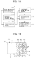
- Figure 1A is a block diagram showing a conceptual configuration of an automatic nesting apparatus according to one embodiment of this invention.
- Figure 1B is an explanatory drawing showing the relationship between a work, a temporary work, and products in this apparatus.
- Figure 2A is a flow chart showing the entire flow of the automatic nesting apparatus.
- Figure 2B is a flow chart showing the details of a preprocessing step in the flow chart.
- Figure 3 is an explanatory drawing of a nesting method executed by the automatic nesting apparatus.
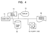
- Figure 4 is a block diagram of a hardware configuration of an automatic programming apparatus including the automatic nesting apparatus.
- Figure 5 is an explanatory drawing of a nesting method executed by an automatic nesting apparatus according to another embodiment of this invention.
- Figure 6 is an explanatory drawing of a nesting method executed by an automatic nesting apparatus according to yet another embodiment of this invention.
- Figure 7 is an explanatory drawing of a conventional nesting method.
- Figure 4 is a block diagram showing a hardware configuration of an automatic programming apparatus including an automatic nesting apparatus according to this invention.
- a storage means including a fixed disc device 12, a floppy disc device 13 and so on, an input means 14 including a keyboard, a mouse and so on, and an output means including a display 15, a graphic printer 16 and so on, are connected to a computer 11.
- the computer 11 includes an internal storage device in addition to a central processing unit, and the internal storage device or the fixed disc device 12 stores programs and data constituting the automatic programming apparatus and automatic nesting apparatus.
- the automatic programming apparatus automatically generates a processing program consisting of an NC program for a plate processing machine such as a laser beam machine or a punch press machine.
- the automatic nesting apparatus is configured as part of the function of the automatic programming apparatus or as an independent function.
- the automatic nesting apparatus in Figure 1B determines the locations of multiple products w that are cut out from the rectangular work W.
- Figure 1A shows a block diagram representing a conceptual configuration of this apparatus.
- the automatic nesting apparatus comprises a work information storage means 1 for storing the shape and size of the work W, a product information storage means 2 for storing the shape and size of the multiple products w, a temporary work setting means 3 for setting, within the range of the rectangle constituting the outline of the work W, a rectangular region sharing one side a (in this example, the short side on the right of this figure) of the rectangle w, as temporary works W1, W2 ⁇ , and a determination means 5 for determining the locations of the multiple products w relative to the temporary works W1, W2 ⁇
- a determination result information storage means 5 for storing the results obtained by the determination means 4, and a pre-processing means 6 are provided. Since this embodiment executes nesting for cut-out processing, the locations of the products w relative to the work W indicate the processing locations of the products w.
- the work information storage means 1 and the product information storage means 2 store information on the work W and the products w, respectively, that are to be nested.
- the determination means 4 Given information on the shapes and sizes of any rectangular work W and each product w, the determination means 4 sets a specified corner of the outline of the work W as a reference position A and lays out the products w as closely as possible from the reference position A toward a corner B in a diagonal direction of the work W. The determination means 4 indicates that the layout is impossible if some of the specified multiple products w cannot be fitted into the work W.
- the determination means 4 determines the locations of the products w relative to the temporary works W1, W2 ⁇ or indicates that the layout is impossible, as in the case of the actual work W.
- the determination means 4 lays out the products w as closely as possible while avoiding the layout of the work holder 17.
- the determination result information storage means 5 stores the results of the locations determined by the determination means 4.
- the temporary work setting means 3 sets an initial value for the temporary work, that is, a region for a first temporary work W1 depending on the shape and size of the work W.
- the temporary work setting means 3 increases the size of the rectangular region up to a second temporary work W2.
- the region is enlarged in the direction perpendicular to one side a that is used as a reference for the work W (the direction along a long side b).
- the incremental size ⁇ L by which the temporary work is sequentially enlarged to W1, W2, W3 ⁇ is set at a constant value in this example.
- the incremental size ⁇ L may be large, for example, 10 cm or may be set in a smaller unit such as 1 mm or 10 mm.
- the pre-processing means 6 executes a specified process before the temporary work W1 is set. It allows the determination means 4 to directly lay out the products w within the work W and if a specified yield or more can be obtained, it completes the nesting process without setting the temporary work W1.
- Figure 2A shows the entire process of this nesting method and Figure 2B shows the details of pre-processing for this process.
- the determination means 4 Before nesting is started, at pre-processing step S1, the determination means 4 carries out nesting for the overall work W, that is, it lays out the products w as closely as possible within the work W (step T1 in Figure 2B).
- the yield of the nesting process is calculated (T2), and if it is higher than or equal to a specified value, that is, if the part that can be used as surplus material is smaller than the specified value, the process directly jumps (T3, T4) to a product location determination step S5 as shown in Figure 1A to determine the locations of the products w relative to the work w.
- the nesting process sequentially creates for multiple works w a layout pattern of multiple products w that cannot be laid out within a single work W in order to provide multiple (types of) layout patterns.
- the nesting process generally jumps to the product location determination step S5 from the pre-processing step S1 when the yield reaches the specified value or more.
- the following nesting process is executed for the last pattern to be created.
- a setting process of the temporary work (S2) is done.
- This process sets, within the range of the rectangular work W, a rectangular region (indicated by chain lines) sharing one side (in this case, a short side) a of the rectangle that is used as a determination reference, as the temporary work W1, as shown in Figure 3A.
- the overall area of the rectangular work W is divided in the longitudinal direction and a specified width L1 at one end of the work W is set as the temporary work W1.
- the determination means 4 executes a product layout process (nesting) for the set temporary work W1 (step S3 in Figure 2).
- This product layout process lays out the products as closely as possible in a diagonal direction of the temporary work W1 starting from the reference position A in a corner of the work. If all products w can be laid out, the process proceeds to the subsequent product location determination process (S5 in Figure 2). Otherwise, the process passes to a temporary work enlargement step (S6) to set the temporary work W2 (the shaded part in Figure 3B) that is obtained by increasing the size of the temporary work region by a specified incremental length ⁇ L1.
- the determination means 4 again executes nesting for the enlarged temporary work W2 (S3).
- the process transfers to the subsequent product location determination step (S5 in Figure 2). Otherwise, it returns to the temporary work enlargement step (S6) to set the temporary work W3 (the shaded part in Figure 3C) that is obtained by further increasing the size of the temporary work region by the specified incremental length ⁇ L1.
- the products w shown in Figure 3C can all be laid out within the temporary work W3 of this size.
- the product location determination step (S5) determines the corresponding locations of the products w, and while storing this result of the layout of the products, recovers the actual work W instead of the temporary works W1, W2, W3 ⁇ and allows the determination result information storage means 5 to store this result of the nesting for the actual work W.
- this automatic nesting apparatus sets, within the region of the work W, a rectangular region sharing one side a of the work W as the temporary works W1, W2 ⁇ and determines the locations of the products w relative to the temporary works W1, W2 ⁇ , the surplus material region S is rectangular and can be reused easily. Consequently, the reuse value of the surplus material can be improved.
- the rectangular region of the temporary work is gradually enlarged toward a long side of the work W to repeat the trial product layout process.
- the region for nesting can be minimized to increase the size of the surplus material region S.
- the determination means 4 in Figure 1 may execute nesting by extending the temporary works W1, W2 ⁇ toward the short side a using the long side b as the reference, as shown in Figures 5A to 5C.
- the long side b used as the reference is set opposite to the long side gripped by the work holder 17 of a plate processing machine such as a punch press.
- the surplus material s can be used effectively even if elongated products w are obtained, and in addition to the region gripped by the work holder 17, the size of the surplus material s can be increased.
- M is the length of the short side of the work
- M1 is the length of the temporary work W1
- ⁇ M is an incremental size.
- the determination means 4 in Figure 1 may execute nesting by setting as the first temporary work region W1 one of two regions obtained by dividing the work W at its center line parallel with the one side a, as shown in Figure 6A, and incrementing the size the temporary works W1, W2 ⁇ by the specified value ⁇ L if the products w cannot be laid out.
- the temporary work may be sequentially enlarged starting from the one side a of the work W as in the example in Figure 3.
- Figure 6 shows the process executed using the short side a as the nesting reference, but even if the long side b is used as the nesting reference as shown in the example in Figure 5, it is possible to use the method that sets as the first temporary work region one of two regions obtained by dividing the work at its center line parallel with the one side (the long side) b and sequentially enlarging the temporary work, as described above, and also enlarging the temporary work starting from the one side b if the yield is insufficient.
- the automatic nesting apparatus includes the temporary work setting means for setting as the temporary work a rectangular region sharing one side of the work and the determination means for determining the locations of the multiple products relative to the temporary work.
- the shape of the surplus material region can be simplified to improve the reuse value of the surplus material.
- the temporary work setting means enlarges the rectangular region used as the temporary work, in the direction perpendicular to one side of the temporary work if the determination has failed to lay out the products within the temporary work, the region for nesting can be minimized to increase the surplus material region.
Landscapes
- Engineering & Computer Science (AREA)
- Human Computer Interaction (AREA)
- Manufacturing & Machinery (AREA)
- Physics & Mathematics (AREA)
- General Physics & Mathematics (AREA)
- Automation & Control Theory (AREA)
- Numerical Control (AREA)
- Warehouses Or Storage Devices (AREA)
Abstract
Description
Claims (3)
- An automatic nesting apparatus for determining the locations of multiple products relative to a rectangular work, characterized in that the apparatus comprises a work information storage means for storing the shape and size of a work, a product information storage means for storing the shape and size of each of the multiple products, a temporary work setting means for setting, within the range of the rectangle constituting the outline of the work, a rectangular region sharing one side of the rectangle, as a temporary work, and a determination means for determining the locations of the multiple products relative to the temporary work.
- An automatic nesting apparatus as in claim 1 characterized in that when, as a result of the processing of the temporary work by the determination means, some of the multiple products cannot be laid out, the temporary work setting means enlarges the rectangular region used as the temporary work, in a direction perpendicular to the one side of the work, and in that the determination means again determines the locations of the multiple products relative to the enlarged temporary work.
- An automatic nesting apparatus as in claim 2 characterized in that if the processing by the determination means and the processing for enlarging the region used as the temporary work when the products cannot be laid out are repeated several times, the work setting means increments the size of the region by a constant value.
Applications Claiming Priority (2)
| Application Number | Priority Date | Filing Date | Title |
|---|---|---|---|
| JP09333897A JP3444136B2 (en) | 1997-04-11 | 1997-04-11 | Automatic nesting device |
| JP93338/97 | 1997-04-11 |
Publications (2)
| Publication Number | Publication Date |
|---|---|
| EP0871100A2 true EP0871100A2 (en) | 1998-10-14 |
| EP0871100A3 EP0871100A3 (en) | 1999-05-26 |
Family
ID=14079492
Family Applications (1)
| Application Number | Title | Priority Date | Filing Date |
|---|---|---|---|
| EP98105980A Withdrawn EP0871100A3 (en) | 1997-04-11 | 1998-04-01 | Automatic nesting apparatus |
Country Status (2)
| Country | Link |
|---|---|
| EP (1) | EP0871100A3 (en) |
| JP (1) | JP3444136B2 (en) |
Cited By (3)
| Publication number | Priority date | Publication date | Assignee | Title |
|---|---|---|---|---|
| WO2009121335A1 (en) * | 2008-03-31 | 2009-10-08 | Trumpf Werkzeugmaschinen Gmbh + Co. Kg | Method for optimizing the occupancy of a pipe or several pipes with several pipe parts to be cut for a machining installation |
| WO2009121334A1 (en) | 2008-03-31 | 2009-10-08 | Trumpf Werkzeugmaschinen Gmbh + Co. Kg | Method and nc part program for controlling a laser cutting system |
| EP2345044A4 (en) * | 2008-09-10 | 2014-01-15 | 9128 5270 Quebec Inc | METHOD FOR MANUFACTURING ALUMINUM PLATES WITH HIGH ELECTRICAL CONDUCTIVITY |
Families Citing this family (1)
| Publication number | Priority date | Publication date | Assignee | Title |
|---|---|---|---|---|
| JP5272515B2 (en) * | 2008-05-23 | 2013-08-28 | 村田機械株式会社 | Nesting apparatus and plate material processing method |
Family Cites Families (1)
| Publication number | Priority date | Publication date | Assignee | Title |
|---|---|---|---|---|
| US3596068A (en) * | 1968-12-30 | 1971-07-27 | California Computer Products | System for optimizing material utilization |
-
1997
- 1997-04-11 JP JP09333897A patent/JP3444136B2/en not_active Expired - Fee Related
-
1998
- 1998-04-01 EP EP98105980A patent/EP0871100A3/en not_active Withdrawn
Cited By (7)
| Publication number | Priority date | Publication date | Assignee | Title |
|---|---|---|---|---|
| WO2009121335A1 (en) * | 2008-03-31 | 2009-10-08 | Trumpf Werkzeugmaschinen Gmbh + Co. Kg | Method for optimizing the occupancy of a pipe or several pipes with several pipe parts to be cut for a machining installation |
| WO2009121334A1 (en) | 2008-03-31 | 2009-10-08 | Trumpf Werkzeugmaschinen Gmbh + Co. Kg | Method and nc part program for controlling a laser cutting system |
| CN101983361B (en) * | 2008-03-31 | 2013-10-09 | 通快机床两合公司 | Method for controlling a laser cutting system |
| CN102137734B (en) * | 2008-03-31 | 2014-09-17 | 通快机床两合公司 | Method for optimizing the occupancy of a pipe or several pipes with several pipe parts to be cut for a machining installation |
| US9199336B2 (en) | 2008-03-31 | 2015-12-01 | Trumpf Werkzeugmaschinen Gmbh + Co. Kg | Method for allocation of one or more pipes with several pipe parts to be cut |
| EP2345044A4 (en) * | 2008-09-10 | 2014-01-15 | 9128 5270 Quebec Inc | METHOD FOR MANUFACTURING ALUMINUM PLATES WITH HIGH ELECTRICAL CONDUCTIVITY |
| US8707543B2 (en) | 2008-09-10 | 2014-04-29 | 9128-5270 Quebec Inc. | Process for making high electrical conductivity aluminium plates |
Also Published As
| Publication number | Publication date |
|---|---|
| EP0871100A3 (en) | 1999-05-26 |
| JP3444136B2 (en) | 2003-09-08 |
| JPH10289010A (en) | 1998-10-27 |
Similar Documents
| Publication | Publication Date | Title |
|---|---|---|
| DE69726431T2 (en) | DEVICE AND METHOD FOR INTEGRATING AN INTELLIGENT MANUFACTURING SYSTEM WITH A SHEET PLANNING AND BENDING SYSTEM | |
| CN112248436B (en) | Multi-laser-based scanning path planning method and device and three-dimensional object manufacturing equipment | |
| US20050107921A1 (en) | Robot operation program modification device | |
| US5208904A (en) | Data processing apparatus and method for preparing data representative of supplemental figure attached to basic figure reproduced on output medium | |
| JP4102480B2 (en) | Method and apparatus for manufacturing bent sheet metal parts | |
| EP4239584A1 (en) | Shape analysis apparatus, shape analysis method, and non-transitory computer-readable recording medium for shape analysis | |
| WO1999063491A1 (en) | Automatic programming apparatus and storage medium for storing graphic data generating program | |
| WO1989006391A1 (en) | Automatic programming method | |
| JP3444136B2 (en) | Automatic nesting device | |
| EP4223526A1 (en) | Data generating program and three-dimensional fabrication system | |
| US5383131A (en) | Method of determining cutting trajectory in N/C machining system | |
| JP3439812B2 (en) | Automatic product arrangement method | |
| JP3444150B2 (en) | Automatic plate removing device | |
| JPH07230309A (en) | Automatic plate blanking device and method therefor | |
| JPH0388737A (en) | Device for cutting base sheet | |
| JP2706266B2 (en) | How to create bending data | |
| US6681144B1 (en) | Process and system for working a workpiece through numerically controlled machine tools | |
| EP4737051A1 (en) | Method for laser cutting at least two parts out of a sheet metal and creating a residual sheet portion from which further parts can be cut | |
| JPH08137533A (en) | Nc nesting working method | |
| JP2865213B2 (en) | Numerical control information creation device | |
| JPH0839165A (en) | Method for arranging tool onto metal sheet working graphic data | |
| JPH07319526A (en) | NC data generation method | |
| KR20240150982A (en) | Nesting device and method | |
| JP4381128B2 (en) | Bending machine control system and method | |
| JPH0639440A (en) | Data preparing method for radius bending |
Legal Events
| Date | Code | Title | Description |
|---|---|---|---|
| PUAI | Public reference made under article 153(3) epc to a published international application that has entered the european phase |
Free format text: ORIGINAL CODE: 0009012 |
|
| AK | Designated contracting states |
Kind code of ref document: A2 Designated state(s): DE |
|
| AX | Request for extension of the european patent |
Free format text: AL;LT;LV;MK;RO;SI |
|
| PUAL | Search report despatched |
Free format text: ORIGINAL CODE: 0009013 |
|
| AK | Designated contracting states |
Kind code of ref document: A3 Designated state(s): AT BE CH CY DE DK ES FI FR GB GR IE IT LI LU MC NL PT SE |
|
| AX | Request for extension of the european patent |
Free format text: AL;LT;LV;MK;RO;SI |
|
| AKX | Designation fees paid |
Free format text: DE |
|
| STAA | Information on the status of an ep patent application or granted ep patent |
Free format text: STATUS: THE APPLICATION IS DEEMED TO BE WITHDRAWN |
|
| 18D | Application deemed to be withdrawn |
Effective date: 19991129 |