EP0870849B1 - Tool for glass molding operations and method of manufacture thereof - Google Patents
Tool for glass molding operations and method of manufacture thereof Download PDFInfo
- Publication number
- EP0870849B1 EP0870849B1 EP98302706A EP98302706A EP0870849B1 EP 0870849 B1 EP0870849 B1 EP 0870849B1 EP 98302706 A EP98302706 A EP 98302706A EP 98302706 A EP98302706 A EP 98302706A EP 0870849 B1 EP0870849 B1 EP 0870849B1
- Authority
- EP
- European Patent Office
- Prior art keywords
- max
- tool
- melt
- glass molding
- less
- Prior art date
- Legal status (The legal status is an assumption and is not a legal conclusion. Google has not performed a legal analysis and makes no representation as to the accuracy of the status listed.)
- Expired - Lifetime
Links
- 239000011521 glass Substances 0.000 title claims abstract description 21
- 238000000034 method Methods 0.000 title claims abstract description 10
- 238000000465 moulding Methods 0.000 title claims abstract description 10
- 238000004519 manufacturing process Methods 0.000 title abstract description 11
- 238000007254 oxidation reaction Methods 0.000 claims abstract description 22
- 230000003647 oxidation Effects 0.000 claims abstract description 20
- 239000000203 mixture Substances 0.000 claims abstract description 8
- 239000012535 impurity Substances 0.000 claims abstract description 5
- 238000005260 corrosion Methods 0.000 claims description 15
- 230000007797 corrosion Effects 0.000 claims description 15
- NINIDFKCEFEMDL-UHFFFAOYSA-N Sulfur Chemical compound [S] NINIDFKCEFEMDL-UHFFFAOYSA-N 0.000 claims description 8
- 229910045601 alloy Inorganic materials 0.000 claims description 6
- 239000000956 alloy Substances 0.000 claims description 6
- 229910052717 sulfur Inorganic materials 0.000 claims description 6
- 229910001105 martensitic stainless steel Inorganic materials 0.000 claims description 5
- 229910052757 nitrogen Inorganic materials 0.000 claims description 5
- 230000001590 oxidative effect Effects 0.000 claims description 5
- 238000012545 processing Methods 0.000 claims description 4
- 230000000694 effects Effects 0.000 claims description 3
- 238000010438 heat treatment Methods 0.000 claims description 3
- 239000000155 melt Substances 0.000 claims 5
- 239000005864 Sulphur Substances 0.000 claims 3
- 229910052739 hydrogen Inorganic materials 0.000 claims 2
- 229910052760 oxygen Inorganic materials 0.000 claims 2
- 238000010926 purge Methods 0.000 claims 2
- 238000005485 electric heating Methods 0.000 claims 1
- 238000007496 glass forming Methods 0.000 claims 1
- 230000002411 adverse Effects 0.000 abstract 1
- 239000011651 chromium Substances 0.000 description 17
- PXHVJJICTQNCMI-UHFFFAOYSA-N Nickel Chemical compound [Ni] PXHVJJICTQNCMI-UHFFFAOYSA-N 0.000 description 13
- 229910001566 austenite Inorganic materials 0.000 description 13
- 229910052804 chromium Inorganic materials 0.000 description 13
- 229910052799 carbon Inorganic materials 0.000 description 11
- OKTJSMMVPCPJKN-UHFFFAOYSA-N Carbon Chemical compound [C] OKTJSMMVPCPJKN-UHFFFAOYSA-N 0.000 description 10
- VYZAMTAEIAYCRO-UHFFFAOYSA-N Chromium Chemical group [Cr] VYZAMTAEIAYCRO-UHFFFAOYSA-N 0.000 description 10
- 239000000463 material Substances 0.000 description 10
- 229910052802 copper Inorganic materials 0.000 description 9
- 239000010949 copper Chemical group 0.000 description 9
- RYGMFSIKBFXOCR-UHFFFAOYSA-N Copper Chemical group [Cu] RYGMFSIKBFXOCR-UHFFFAOYSA-N 0.000 description 8
- 229910000734 martensite Inorganic materials 0.000 description 8
- 229910052759 nickel Inorganic materials 0.000 description 7
- 238000012360 testing method Methods 0.000 description 7
- 229910052751 metal Inorganic materials 0.000 description 6
- 239000002184 metal Substances 0.000 description 6
- 238000010791 quenching Methods 0.000 description 6
- 230000009466 transformation Effects 0.000 description 6
- 229910052782 aluminium Inorganic materials 0.000 description 5
- XAGFODPZIPBFFR-UHFFFAOYSA-N aluminium Chemical compound [Al] XAGFODPZIPBFFR-UHFFFAOYSA-N 0.000 description 5
- 229910052750 molybdenum Inorganic materials 0.000 description 5
- 229910052710 silicon Inorganic materials 0.000 description 5
- 229910001220 stainless steel Inorganic materials 0.000 description 5
- 238000005728 strengthening Methods 0.000 description 5
- 239000011593 sulfur Substances 0.000 description 5
- 238000005496 tempering Methods 0.000 description 5
- IJGRMHOSHXDMSA-UHFFFAOYSA-N Atomic nitrogen Chemical compound N#N IJGRMHOSHXDMSA-UHFFFAOYSA-N 0.000 description 4
- XUIMIQQOPSSXEZ-UHFFFAOYSA-N Silicon Chemical compound [Si] XUIMIQQOPSSXEZ-UHFFFAOYSA-N 0.000 description 4
- 229910052748 manganese Inorganic materials 0.000 description 4
- 239000011572 manganese Substances 0.000 description 4
- 238000001556 precipitation Methods 0.000 description 4
- 239000010703 silicon Substances 0.000 description 4
- 239000006104 solid solution Substances 0.000 description 4
- 239000003381 stabilizer Substances 0.000 description 4
- CWYNVVGOOAEACU-UHFFFAOYSA-N Fe2+ Chemical compound [Fe+2] CWYNVVGOOAEACU-UHFFFAOYSA-N 0.000 description 3
- PWHULOQIROXLJO-UHFFFAOYSA-N Manganese Chemical compound [Mn] PWHULOQIROXLJO-UHFFFAOYSA-N 0.000 description 3
- ZOKXTWBITQBERF-UHFFFAOYSA-N Molybdenum Chemical compound [Mo] ZOKXTWBITQBERF-UHFFFAOYSA-N 0.000 description 3
- 238000004512 die casting Methods 0.000 description 3
- 238000005242 forging Methods 0.000 description 3
- 239000011733 molybdenum Substances 0.000 description 3
- 239000002245 particle Substances 0.000 description 3
- 230000008569 process Effects 0.000 description 3
- 230000009467 reduction Effects 0.000 description 3
- 229910052720 vanadium Inorganic materials 0.000 description 3
- XLYOFNOQVPJJNP-UHFFFAOYSA-N water Substances O XLYOFNOQVPJJNP-UHFFFAOYSA-N 0.000 description 3
- 230000009471 action Effects 0.000 description 2
- 238000005275 alloying Methods 0.000 description 2
- BHEPBYXIRTUNPN-UHFFFAOYSA-N hydridophosphorus(.) (triplet) Chemical compound [PH] BHEPBYXIRTUNPN-UHFFFAOYSA-N 0.000 description 2
- 239000006060 molten glass Substances 0.000 description 2
- 238000005498 polishing Methods 0.000 description 2
- 230000004044 response Effects 0.000 description 2
- 238000009628 steelmaking Methods 0.000 description 2
- 238000010998 test method Methods 0.000 description 2
- LEONUFNNVUYDNQ-UHFFFAOYSA-N vanadium atom Chemical compound [V] LEONUFNNVUYDNQ-UHFFFAOYSA-N 0.000 description 2
- 229910000859 α-Fe Inorganic materials 0.000 description 2
- 229910001111 Fine metal Inorganic materials 0.000 description 1
- 238000007792 addition Methods 0.000 description 1
- 230000009286 beneficial effect Effects 0.000 description 1
- 230000015572 biosynthetic process Effects 0.000 description 1
- 230000015556 catabolic process Effects 0.000 description 1
- -1 chromium carbides Chemical class 0.000 description 1
- 230000001010 compromised effect Effects 0.000 description 1
- 239000000470 constituent Substances 0.000 description 1
- 238000001816 cooling Methods 0.000 description 1
- 238000007872 degassing Methods 0.000 description 1
- 238000006731 degradation reaction Methods 0.000 description 1
- 230000002939 deleterious effect Effects 0.000 description 1
- 238000011161 development Methods 0.000 description 1
- 238000010891 electric arc Methods 0.000 description 1
- 238000011156 evaluation Methods 0.000 description 1
- 238000002474 experimental method Methods 0.000 description 1
- 230000009969 flowable effect Effects 0.000 description 1
- 238000007542 hardness measurement Methods 0.000 description 1
- 229910000765 intermetallic Inorganic materials 0.000 description 1
- 239000011159 matrix material Substances 0.000 description 1
- 238000002844 melting Methods 0.000 description 1
- 230000008018 melting Effects 0.000 description 1
- 150000001247 metal acetylides Chemical class 0.000 description 1
- 238000010137 moulding (plastic) Methods 0.000 description 1
- 229910052758 niobium Inorganic materials 0.000 description 1
- 150000004767 nitrides Chemical class 0.000 description 1
- 230000003389 potentiating effect Effects 0.000 description 1
- 238000004881 precipitation hardening Methods 0.000 description 1
- 230000000171 quenching effect Effects 0.000 description 1
- 238000007790 scraping Methods 0.000 description 1
- 230000006641 stabilisation Effects 0.000 description 1
- 238000011105 stabilization Methods 0.000 description 1
- 230000000087 stabilizing effect Effects 0.000 description 1
- 239000010935 stainless steel Substances 0.000 description 1
- 229910001256 stainless steel alloy Inorganic materials 0.000 description 1
- 229910052719 titanium Inorganic materials 0.000 description 1
- 229910052721 tungsten Inorganic materials 0.000 description 1
Images

Classifications
-
- C—CHEMISTRY; METALLURGY
- C03—GLASS; MINERAL OR SLAG WOOL
- C03B—MANUFACTURE, SHAPING, OR SUPPLEMENTARY PROCESSES
- C03B11/00—Pressing molten glass or performed glass reheated to equivalent low viscosity without blowing
- C03B11/06—Construction of plunger or mould
-
- B—PERFORMING OPERATIONS; TRANSPORTING
- B22—CASTING; POWDER METALLURGY
- B22D—CASTING OF METALS; CASTING OF OTHER SUBSTANCES BY THE SAME PROCESSES OR DEVICES
- B22D17/00—Pressure die casting or injection die casting, i.e. casting in which the metal is forced into a mould under high pressure
- B22D17/20—Accessories: Details
- B22D17/22—Dies; Die plates; Die supports; Cooling equipment for dies; Accessories for loosening and ejecting castings from dies
- B22D17/2209—Selection of die materials
-
- C—CHEMISTRY; METALLURGY
- C03—GLASS; MINERAL OR SLAG WOOL
- C03B—MANUFACTURE, SHAPING, OR SUPPLEMENTARY PROCESSES
- C03B9/00—Blowing glass; Production of hollow glass articles
- C03B9/30—Details of blowing glass; Use of materials for the moulds
- C03B9/48—Use of materials for the moulds
-
- C—CHEMISTRY; METALLURGY
- C22—METALLURGY; FERROUS OR NON-FERROUS ALLOYS; TREATMENT OF ALLOYS OR NON-FERROUS METALS
- C22C—ALLOYS
- C22C38/00—Ferrous alloys, e.g. steel alloys
- C22C38/18—Ferrous alloys, e.g. steel alloys containing chromium
- C22C38/40—Ferrous alloys, e.g. steel alloys containing chromium with nickel
- C22C38/42—Ferrous alloys, e.g. steel alloys containing chromium with nickel with copper
-
- C—CHEMISTRY; METALLURGY
- C22—METALLURGY; FERROUS OR NON-FERROUS ALLOYS; TREATMENT OF ALLOYS OR NON-FERROUS METALS
- C22C—ALLOYS
- C22C38/00—Ferrous alloys, e.g. steel alloys
- C22C38/18—Ferrous alloys, e.g. steel alloys containing chromium
- C22C38/40—Ferrous alloys, e.g. steel alloys containing chromium with nickel
- C22C38/44—Ferrous alloys, e.g. steel alloys containing chromium with nickel with molybdenum or tungsten
-
- C—CHEMISTRY; METALLURGY
- C22—METALLURGY; FERROUS OR NON-FERROUS ALLOYS; TREATMENT OF ALLOYS OR NON-FERROUS METALS
- C22C—ALLOYS
- C22C38/00—Ferrous alloys, e.g. steel alloys
- C22C38/18—Ferrous alloys, e.g. steel alloys containing chromium
- C22C38/40—Ferrous alloys, e.g. steel alloys containing chromium with nickel
- C22C38/46—Ferrous alloys, e.g. steel alloys containing chromium with nickel with vanadium
-
- Y—GENERAL TAGGING OF NEW TECHNOLOGICAL DEVELOPMENTS; GENERAL TAGGING OF CROSS-SECTIONAL TECHNOLOGIES SPANNING OVER SEVERAL SECTIONS OF THE IPC; TECHNICAL SUBJECTS COVERED BY FORMER USPC CROSS-REFERENCE ART COLLECTIONS [XRACs] AND DIGESTS
- Y02—TECHNOLOGIES OR APPLICATIONS FOR MITIGATION OR ADAPTATION AGAINST CLIMATE CHANGE
- Y02P—CLIMATE CHANGE MITIGATION TECHNOLOGIES IN THE PRODUCTION OR PROCESSING OF GOODS
- Y02P40/00—Technologies relating to the processing of minerals
- Y02P40/50—Glass production, e.g. reusing waste heat during processing or shaping
- Y02P40/57—Improving the yield, e-g- reduction of reject rates
Definitions
- This invention relates generally to tools for glass molds and other tooling applications in which the tooling is subjected to corrosive and/or elevated temperature environments, including plastic molds and non-ferrous die casting applications, and methods of manufacture thereof It relates specifically to tools which are exposed to oxidizing conditions during operations with a consequent undesirable degradation of the working surfaces thereof due to oxidation
- the materials of choice for mold components in the glass industry are martensitic stainless steels.
- the 420 type has been the preferred choice for molds used in glass applications due to its strength and wear resistance properties in addition to oxidation and corrosion resistance
- the invention is a glass mold tool (or part, the term being used interchangeably herein), which meets the demanding requirement for glass mold components in terms of oxidation resistance, corrosion resistance, high strength and high wear resistance properties
- the invention is a mold component in a three part mold assembly which includes a plunger, a bottom mold and a shell for use in a main assembly panel press which is formed from a high chromium, copper bearing, martensitic stainless steel alloy.
- the tool has good hot workability even though it contains a high level of chromium and, by current industry standards, a low level of nickel It also has excellent corrosion resistance while maintaining the necessary strength and wear resistance properties and, most important of all, high oxidation resistance so that the mold components maintain their high polish over long production runs
- the tool of this invention which is defined by the appended claims, is a part (plunger, shell, bottom mold) of a mold assembly for television picture tubes, is formed from a high chromium, copper bearing, martensitic stainless steel alloy capable of achieving a high polish
- the composition of the tool is based on thermodynamic phase stability , which allows a martensitic stainless steel with good hot workability to be developed in the presence of high chromium levels and low nickel levels Typical high chromium martensitic stainless steels rely upon nickel to stabilize austenite to a degree which will allow the transformation of austenite to martensite
- the tool of the invention has a relatively low nickel content but the austenite to martensite transformation is achieved by introducing copper and increasing the carbon content
- the copper provides increased resistance to oxidation and corrosion as well as precipitation strengthening Copper and nickel additions provide a wide austenite phase field which imparts good hot workability and allows martensitic transformation above room temperature Additionally, the tool can achieve a high polish
- the tool is produced using electric arc furnace melting, vacuum arc degassing as exemplified by U S Patents Nos. 3,501,289, 3,635, 696; 4,069,039, 4,541,862, and 4,600,427, and wide die forging.
- the double vacuum process (U.S Patent No 5,252,120), the disclosure of which is incorporated herein by reference, may be used to produce premium quality material for glass contact applications requiring a lens quality surface finish in the as-formed condition
- the tool will also be advantageous in tooling applications for plastic molds, non-ferrous die casting, and components subjected to corrosive and/or elevated temperature environments
- the invention is illustrated more or less diagrammatically in the Figure which illustrates, in exemplary form, a three part tool for the manufacture of high resolution television tubes in cross section together with a formed workpiece to the left of the movement axis and the cavity to the right of the movement axis
- a tool here a three part mold for high resolution television tubes, is indicated generally at 10
- the tool which is shown in cross section, consists of bottom mold 11, a top mold or plunger 12, and a shell 13
- the bottom mold, plunger and shell form a cavity 14 into which molten glass at a high temperature is placed, usually in gob form
- Upon closure of the mold the soft, flowable glass is pressed into the configuration illustrated by the cavity 14 by conventional means.
- One half of the formed workpiece is indicated generally at 15.
- the special material is a stainless steel alloy having the following compositions in weight percent Broad chemistry range. x-maximum C Mn P S Si Ni Cr Mo V Cu Al 0.23/ 0.40/ 0.040x 0.030x 0.00/ 1.0/ 14.0/ 0.25/ 0.10x 0.50/ 0.030x 0.38 1.00 1.20 3.0 20.0 1.00 1.50
- a preferred composition is as follows Preferred chemistry range, x-maximum C Mn P S Si Ni Cr Mo V Cu Al 0.28/ 0.40/ 0.030x 0.010x 0.20/ 1.50/ 14.0/ 0.35/ 0.02/ 0.85/ 0.02 x 0.35 0.60 0.50 1.80 18 .0 0.55 0.08 1.15
- phase modeling was used along with experimentation to establish these ranges for the tool chemistry Specifically, phase modeling was used to balance the ferrite stabilizing alloying elements (Cr, Si, and Mo) with the austenite stabilizers (C, Mn, Ni, and Cu) in order to provide a wide austenite phase field at forging and heat treatment processing temperatures while maintaining a chromium level of at least 14 w / o to enhance corrosion resistance.
- Other alloying constraints were imposed to optimize oxidation resistance, corrosion resistance, softening resistance at elevated temperatures, and good hot workability Each element contributes to the overall capability of the tool The effects of each element are detailed below
- Manganese provides mild solid solution strengthening and increases the alloy's hardenability If present in sufficient quantity, manganese binds sulfur into a non-metallic compound reducing the deleterious effects of free sulfur on the ductility of the tool material Manganese is also an austenite stabilizer, and levels above 1.00 w / o can cause an overstabilization problem akin to that found with high carbon levels
- Silicon is used for de-oxidation during steel making Additionally, silicon increases oxidation resistance, imparts a mild increase in strength due to solid solution strengthening, and increases the hardenability ofthe tool. Silicon mildly stabilizes ferrite, and silicon levels between 0.20 w / o and 0.50 w / o are desirable for de-oxidation and phase stabilization in the tool
- Nickel imparts minor solid solution strengthening, extends hardenability, and is a strong austenite stabilizer Quantities between 1.00 w / o and 3.00 w / o will provide the wide austenite phase field for good hot workability while not suppressing the martensite transformation temperatures below acceptable limits
- Chromium moderately enhances hardenability, mildly strengthens by solid solution, and greatly improves wear resistance when combined with carbon to form metal carbide When present in concentrations above 12 w / o , chromium offers high oxide and corrosion resistance To provide greater oxide and corrosion resistance, a minimum of 14 w / o chromium is required Up to 20 w / o can be added without reducing the stability of the austenite phase field to the extent that hot workability is compromised
- Molybdenum strongly improves the hardenability, increases corrosion resistance, reduces the propensity of temper embnttlement, and yields a strengthened tool when heated in the 1000°-1200° F range by precipitation of fine metal carbide (M 2 C)
- M 2 C fine metal carbide
- the molybdenum rich metal carbides provide increased wear resistance, improve hot hardness and resist coarsening below the A 1 Molybdenum quantities up to 1.00 w / o allow these benefits to be realized without compromising hot workability
- Copper augments the hardenability slightly, improves oxidation and corrosion resistance, and imparts strength through precipitation of copper rich particles Copper levels between 0.50 w / o and 1.50 w / o allow gains in oxidation and corrosion resistance, as well as precipitation hardening, without significantly lowering the martensitic transformation temperature
- Aluminum effectively de-oxidizes when used during steel making and provides grain refinement when combined with nitrogen to form fine aluminum nitrides
- Aluminum levels must be kept below 0.30 w / o to ensure preferential stream flow during ingot teeming
- Sulfur and phosphorous are not desired elements and are considered to be impurities Sulfur greatly improves machinability, but at the cost of a decrease in polishability, ductility, and toughness Due to the negative impact on polishability and toughness, sulfur levels are tolerated to a maximum of 0.030, and preferably of 0.010 w / o Phosphorous is similarly tolerated to levels of 0.040, and preferably of 0.030 w / o due to its tendency to decrease ductility by segregating to grain boundaries when tempering between 370 and 480 °C (700° and 900° F)
- Vanadium greatly extends the hardenability, and binds with carbon and nitrogen to produce a M(C,N) type carbo-nitride Vanadium carbo-nitrides refine the grain size by pinning grain boundaries and impart strengthening when precipitated out in the 538 and 649 °C (1000° to 1200° F) range
- Hardenability defines the depth to which a bar can be hardened, and is typically measured by hardness as a function of depth beneath the quenched surface. In this case, hardenability was measured in accordance with ASTM A255 by the standard end quench test method End quench test data for heat no.
- the ingots were converted via wide die forging into 76 x 607 x 2540 mm (3 x 24 x 100 inch) plates for glass panel ring mold stock
- the plates were spheroidized by way of a quench and double temper scheme listed in Table 6 to 300 Brinell hardness number (BHN) Spheroidization treatment Step no Process Temperature (°F) Time (hr. ) 1 Normalize (air cool ) 1010°C (1850) 20 2 Temper (air cool) 649°C (1200) 20 3 Temper (air cool ) 704°C (1300) 20
- Hardenability data is listed in Table 7 Again, hardenability was measured in accordance with ASTM A255 by the standard end quench test method End quench test data for heat no. 260686 'J' Distance (sixteenths of an inch) Hardness (Rockwell, C scale) 'J' Distance (sixteenths of an inch) Hardness (Rockwell, C scale) 1 50 20.6 mm (13) 47 2 49 22.2 mm (14) 46 3 48 23.8 mm (15) 46 4 48 25.4 mm (16) 46 5 48 28.6 mm (18) 45 6 48 31.7 mm (20) 45 7 48 34.9 mm (22) 45 8 48 38.1 mm (24) 45 9 47 41.3 mm (26) 45 10 47 44.5 mm (28) 44 11 47 47.6 mm (30) 44 12 47 50.8 mm (32) 44
- the temper response was established through isochronal hardness vs temperature data, presented graphically in Graph 1 and listed in Table 8
- the experiment established both the maximum hardness capability of the tool and the effects of tempering on hardness
- the data were generated by water quenching one inch cubes of the tool material from 1010°C (1850°F) and then tempering each one at a selected temperature below the A 1c for a time of four hours Hardness measurements were taken after the samples were cooled to room temperature Isochronal hardness vs.
- tempering temperature data for water quenched heat 260686 Tempering Temperature (°F ) Hardness (Brinell hardness number, 3000 kg load) As Quenched 522 371°C (700) 503 427°C (800) 507 482°C (900) 499 538°C (1000) 375 593°C (1100) 321 649°C (1200) 293 704°C (1300) 298 732°C (1350) 323 760°C (1400) 335
- the softening resistance was determined by constructing an isothermal hardness vs time curve which is presented graphically in Graph 2 and listed in Table 9
- a temperature of 704°C (1300° F) was selected since this temperature lies near the A 1e of the tool, calculated to be 718°C (1325° F), where softening conditions are most pronounced
- the isothermal curve shows that the quenched condition resists softening at 704° C (1300° F) even after 25 hours Isothermal hardness vs. time data at 704°C (1300° F) for water quenched heat 260686 Time (hours) Hardness (Brinell hardness number) 2 290 4 298 8 304 16 293 24 293
- Tools 11, 12 and 13, and particularly tool 13, when composed of the constituents as above descnbed, will take and hold a high polish during long production runs with the result that rejections traceable to oxidation on the tool will either be eliminated or drastically reduced to an acceptable level over long production runs.
Landscapes
- Chemical & Material Sciences (AREA)
- Engineering & Computer Science (AREA)
- Materials Engineering (AREA)
- Organic Chemistry (AREA)
- Mechanical Engineering (AREA)
- Metallurgy (AREA)
- Manufacturing & Machinery (AREA)
- Moulds For Moulding Plastics Or The Like (AREA)
- Glass Compositions (AREA)
- Manufacture And Refinement Of Metals (AREA)
- Refinement Of Pig-Iron, Manufacture Of Cast Iron, And Steel Manufacture Other Than In Revolving Furnaces (AREA)
- Manufacture Of Electron Tubes, Discharge Lamp Vessels, Lead-In Wires, And The Like (AREA)
- Surface Treatment Of Glass (AREA)
- Treatment Of Steel In Its Molten State (AREA)
- Vessels, Lead-In Wires, Accessory Apparatuses For Cathode-Ray Tubes (AREA)
- Forging (AREA)
- Heat Treatment Of Articles (AREA)
Abstract
Description
- This invention relates generally to tools for glass molds and other tooling applications in which the tooling is subjected to corrosive and/or elevated temperature environments, including plastic molds and non-ferrous die casting applications, and methods of manufacture thereof It relates specifically to tools which are exposed to oxidizing conditions during operations with a consequent undesirable degradation of the working surfaces thereof due to oxidation
- There is a need for longer lived tools useable in oxidizing environments Such tools are frequently required to maintain a high degree of polish during long production runs so that the workpiece, after removal from the tooling, has a smooth, blemish free surface The glass industry, which is characterized by tight finish specifications, is a prime example of such an application, and the invention will be described in connection with this industry, though it will be understood that the invention has application to certain tooling applications in the plastic molding, non-ferrous die casting, and other corrosive environment and elevated temperature applications
- Specifically, in the glass industry, and particularly that portion of it devoted to the production of television tubes, there is a demand for mold materials which are resistant to oxidation when in contact with molten glass for long periods of time This stems from the fact that after a glass television viewing screen has been formed, usually in a three part mold, at least one of the mold pans must be retracted to a part clearing position while in contact, at least briefly, with the formed screen, in other words, sliding contact occurs between the just formed workpiece, and at least one component of the multi-component mold. It will be understood that all components of the mold have a smooth, highly polished surface so that the formed screen will have no surface imperfections or irregularities which would result in a distortion of light transmitted through the screen If any component of the multi-part mold, and particularly the retractable component which makes sliding contact with the just formed workpiece, has a rough surface, the surface of the just formed, but still deformable, part will reflect the surface discontinuity of the mold, and the formed part will be unacceptable The oxidation which forms on the tool is sufficient, after a production run of a duration shorter than desired, to create a rough surface on the formed workpiece and subsequent rejection of the workpiece
- At the present time, the materials of choice for mold components in the glass industry are martensitic stainless steels. The 420 type has been the preferred choice for molds used in glass applications due to its strength and wear resistance properties in addition to oxidation and corrosion resistance
- Unfortunately, the oxidation and corrosion resistance of 420 type stainless steel is not sufficiently capable of withstanding the temperatures and oxidizing environment in the glass industry for extensive times Because of these limitations, glass mold components manufactured from 420 type stainless steels must be periodically removed from service to remove the oxide build-up that forms on them over time
- The invention is a glass mold tool (or part, the term being used interchangeably herein), which meets the demanding requirement for glass mold components in terms of oxidation resistance, corrosion resistance, high strength and high wear resistance properties In essence, the invention is a mold component in a three part mold assembly which includes a plunger, a bottom mold and a shell for use in a main assembly panel press which is formed from a high chromium, copper bearing, martensitic stainless steel alloy. The tool has good hot workability even though it contains a high level of chromium and, by current industry standards, a low level of nickel It also has excellent corrosion resistance while maintaining the necessary strength and wear resistance properties and, most important of all, high oxidation resistance so that the mold components maintain their high polish over long production runs
- Specifically, the tool of this invention, which is defined by the appended claims, is a part (plunger, shell, bottom mold) of a mold assembly for television picture tubes, is formed from a high chromium, copper bearing, martensitic stainless steel alloy capable of achieving a high polish The composition of the tool is based on thermodynamic phase stability , which allows a martensitic stainless steel with good hot workability to be developed in the presence of high chromium levels and low nickel levels Typical high chromium martensitic stainless steels rely upon nickel to stabilize austenite to a degree which will allow the transformation of austenite to martensite The tool of the invention has a relatively low nickel content but the austenite to martensite transformation is achieved by introducing copper and increasing the carbon content The copper provides increased resistance to oxidation and corrosion as well as precipitation strengthening Copper and nickel additions provide a wide austenite phase field which imparts good hot workability and allows martensitic transformation above room temperature Additionally, the tool can achieve a high polish and resists softening better than 420 type stainless steels at elevated temperatures
- The tool is produced using electric arc furnace melting, vacuum arc degassing as exemplified by U S Patents Nos. 3,501,289, 3,635, 696; 4,069,039, 4,541,862, and 4,600,427, and wide die forging. The double vacuum process (U.S Patent No 5,252,120), the disclosure of which is incorporated herein by reference, may be used to produce premium quality material for glass contact applications requiring a lens quality surface finish in the as-formed condition
- The tool will also be advantageous in tooling applications for plastic molds, non-ferrous die casting, and components subjected to corrosive and/or elevated temperature environments
- The invention is illustrated more or less diagrammatically in the Figure which illustrates, in exemplary form, a three part tool for the manufacture of high resolution television tubes in cross section together with a formed workpiece to the left of the movement axis and the cavity to the right of the movement axis
- Referring now to the Figure, a tool, here a three part mold for high resolution television tubes, is indicated generally at 10 The tool, which is shown in cross section, consists of bottom mold 11, a top mold or plunger 12, and a
shell 13 The bottom mold, plunger and shell form acavity 14 into which molten glass at a high temperature is placed, usually in gob form Upon closure of the mold the soft, flowable glass is pressed into the configuration illustrated by thecavity 14 by conventional means. One half of the formed workpiece is indicated generally at 15. - After forming, including cooling to a point at which the workpiece is self-sustaining, the tool is opened and the workpiece ejected following which it is subjected to further processing In this connection it will be noted that, during the ejection process, there is no sliding action between either (a) the plunger 12 or the
bottom 14 on the one hand, and (b) the formed workpiece, since the direction of movement of the plunger 12 andbottom mold 14 lie along movement axis 16 Specifically, since theflanges surfaces flanges outside viewing area 21 of the workpiece, and again there will be no significant sliding contact between the workpiece and bottom mold 11 after the first increment of relative movement between the mold and the workpiece Any slight imperfections which may be present on the mainoutside viewing area 21 may be readily removed by a subsequent simple polishing operation The main inside viewing area 22 is used as formed - It will be noted however that when
shell 13 is retracted from its illustrated position with respect to a formed workpiece, there will be a scraping or sliding action between thecavity forming area 23 on the shell and theoutside surface 24 offlanges shell 13 in the form of oxidation irregularities will be reflected on theoutside surfaces 24 of the workpiece, usually in the form of a long scrape, or ridge, depending on the shape of the oxidation imperfection in thecavity forming area 23 of the shell - It should also be noted that oxidation build-up on
mold component surface 25 which forms the mainoutside viewing area 21 will result in discontinuities on the mainoutside viewing area 21 These discontinuities will require additional polishing to produce an acceptable picture tube - It has been discovered that molding imperfections in
flanges Broad chemistry range. x-maximum C Mn P S Si Ni Cr Mo V Cu Al 0.23/ 0.40/ 0.040x 0.030x 0.00/ 1.0/ 14.0/ 0.25/ 0.10x 0.50/ 0.030x 0.38 1.00 1.20 3.0 20.0 1.00 1.50 - Alternatively, a preferred composition is as follows
Preferred chemistry range, x-maximum C Mn P S Si Ni Cr Mo V Cu Al 0.28/ 0.40/ 0.030x 0.010x 0.20/ 1.50/ 14.0/ 0.35/ 0.02/ 0.85/ 0.02 x 0.35 0.60 0.50 1.80 18 .0 0.55 0.08 1.15 - Referring now to the foregoing compositions, the rationale for the development thereof is as follows
- Thermodynamic phase modeling was used along with experimentation to establish these ranges for the tool chemistry Specifically, phase modeling was used to balance the ferrite stabilizing alloying elements (Cr, Si, and Mo) with the austenite stabilizers (C, Mn, Ni, and Cu) in order to provide a wide austenite phase field at forging and heat treatment processing temperatures while maintaining a chromium level of at least 14 w/o to enhance corrosion resistance. Other alloying constraints were imposed to optimize oxidation resistance, corrosion resistance, softening resistance at elevated temperatures, and good hot workability Each element contributes to the overall capability of the tool The effects of each element are detailed below
- Carbon determines the as quenched hardness, increases the tool's hardenabililty, and is a potent austenite stabilizer Additionally, carbon combines with a number of different elements, such as Cr, Mo, V, Ti, Nb, and W, and forms a number of metal carbide phases Metal carbide particles enhance wear resistance and the MC type metal carbide provides grain refinement through particle pinning To ensure adequate metal carbide formation for wear resistance and grain refinement and to impart the necessary as quenched hardness, a minimum carbon content of 0.23 w/o is required Increasing the carbon level above 0.38 w/o, however, is undesirable for three reasons First, higher carbon levels produce an overabundance of carbide phase which reduces polishability of the tooling Second, the precipitation of chromium carbides depletes the ferritic matrix of beneficial chromium which lowers the alloy's oxidation and corrosion resistance Third, higher carbon levels will over-stabilize the austenite phase Incomplete transformation can result from this since over-stabilizing austenite will depress the martensite start and finish temperatures below room temperature
- Manganese provides mild solid solution strengthening and increases the alloy's hardenability If present in sufficient quantity, manganese binds sulfur into a non-metallic compound reducing the deleterious effects of free sulfur on the ductility of the tool material Manganese is also an austenite stabilizer, and levels above 1.00 w/o can cause an overstabilization problem akin to that found with high carbon levels
- Silicon is used for de-oxidation during steel making Additionally, silicon increases oxidation resistance, imparts a mild increase in strength due to solid solution strengthening, and increases the hardenability ofthe tool. Silicon mildly stabilizes ferrite, and silicon levels between 0.20 w/o and 0.50 w/o are desirable for de-oxidation and phase stabilization in the tool
- Nickel imparts minor solid solution strengthening, extends hardenability, and is a strong austenite stabilizer Quantities between 1.00 w/o and 3.00 w/o will provide the wide austenite phase field for good hot workability while not suppressing the martensite transformation temperatures below acceptable limits
- Chromium moderately enhances hardenability, mildly strengthens by solid solution, and greatly improves wear resistance when combined with carbon to form metal carbide When present in concentrations above 12 w/o, chromium offers high oxide and corrosion resistance To provide greater oxide and corrosion resistance, a minimum of 14 w/o chromium is required Up to 20 w/o can be added without reducing the stability of the austenite phase field to the extent that hot workability is compromised
- Molybdenum strongly improves the hardenability, increases corrosion resistance, reduces the propensity of temper embnttlement, and yields a strengthened tool when heated in the 1000°-1200° F range by precipitation of fine metal carbide (M2C) The molybdenum rich metal carbides provide increased wear resistance, improve hot hardness and resist coarsening below the A1 Molybdenum quantities up to 1.00 w/o allow these benefits to be realized without compromising hot workability
- Copper augments the hardenability slightly, improves oxidation and corrosion resistance, and imparts strength through precipitation of copper rich particles Copper levels between 0.50 w/o and 1.50 w/o allow gains in oxidation and corrosion resistance, as well as precipitation hardening, without significantly lowering the martensitic transformation temperature
- Aluminum effectively de-oxidizes when used during steel making and provides grain refinement when combined with nitrogen to form fine aluminum nitrides Aluminum levels must be kept below 0.30 w/o to ensure preferential stream flow during ingot teeming
- Sulfur and phosphorous are not desired elements and are considered to be impurities Sulfur greatly improves machinability, but at the cost of a decrease in polishability, ductility, and toughness Due to the negative impact on polishability and toughness, sulfur levels are tolerated to a maximum of 0.030, and preferably of 0.010 w/o Phosphorous is similarly tolerated to levels of 0.040, and preferably of 0.030 w/o due to its tendency to decrease ductility by segregating to grain boundaries when tempering between 370 and 480 °C (700° and 900° F)
- Vanadium greatly extends the hardenability, and binds with carbon and nitrogen to produce a M(C,N) type carbo-nitride Vanadium carbo-nitrides refine the grain size by pinning grain boundaries and impart strengthening when precipitated out in the 538 and 649 °C (1000° to 1200° F) range
- A trial heat was melted to the chemistry listed in Table 3 During teeming of the first trial heat, poor stream fluidity prevented complete filling of the ingots
Chemistry of heat no. 260664 C Mn P S Si Ni Cr Mo V Cu Al 0.35 0.51 0.023 0.006 0.34 2.08 15.27 0.44 0.05 0.87 0.035 - Material for a hardenability test was salvaged from the short poured ingots, and is presented in Table 4. Hardenability defines the depth to which a bar can be hardened, and is typically measured by hardness as a function of depth beneath the quenched surface. In this case, hardenability was measured in accordance with ASTM A255 by the standard end quench test method
End quench test data for heat no. 260664 'J' distance (sixteenths of an inch) Hardness (Rockwell, C scale) 'J' distance (sixteenths of an inch) Hardness (Rockwell, C scale ) 1 51 13 49 2 50 14 49 3 50 15 49 4 50 16 49 5 50 18 49 6 50 20 49 7 50 22 48 8 49 24 48 9 49 26 48 10 49 28 48 11 49 30 48 12 49 32 48 - Another heat was melted to the chemistry listed in Table 5 The aluminum content was reduced to 0.020 weight percent (w/o) maximum to improve stream flow during ingot teeming Modifying the original aluminum content successfully solved the fluidity problem, and this heat was teemed without difficulty into four 785 mm Ø x 4039 mm long (31 inch Ø x 159 inch long)ingots
Chemistry of heat no. 260686 C Mn P S Si Ni Cr Mo V Cu Al 0.37 0.55 0.024 0.006 0.43 1.96 15.70 0.44 0.05 0.98 0.018 - The ingots were converted via wide die forging into 76 x 607 x 2540 mm (3 x 24 x 100 inch) plates for glass panel ring mold stock The plates were spheroidized by way of a quench and double temper scheme listed in Table 6 to 300 Brinell hardness number (BHN)
Spheroidization treatment Step no Process Temperature (°F) Time (hr. ) 1 Normalize (air cool ) 1010°C (1850) 20 2 Temper (air cool) 649°C (1200) 20 3 Temper (air cool ) 704°C (1300) 20 - Material was removed from two plates for mechanical testing and microstructural evaluation Hardenability, temper response, softening resistance, and tensile data were collected using this material
- Hardenability data is listed in Table 7 Again, hardenability was measured in accordance with ASTM A255 by the standard end quench test method
End quench test data for heat no. 260686 'J' Distance (sixteenths of an inch) Hardness (Rockwell, C scale) 'J' Distance (sixteenths of an inch) Hardness (Rockwell, C scale) 1 50 20.6 mm (13) 47 2 49 22.2 mm (14) 46 3 48 23.8 mm (15) 46 4 48 25.4 mm (16) 46 5 48 28.6 mm (18) 45 6 48 31.7 mm (20) 45 7 48 34.9 mm (22) 45 8 48 38.1 mm (24) 45 9 47 41.3 mm (26) 45 10 47 44.5 mm (28) 44 11 47 47.6 mm (30) 44 12 47 50.8 mm (32) 44 - The temper response was established through isochronal hardness vs temperature data, presented graphically in Graph 1 and listed in Table 8 The experiment established both the maximum hardness capability of the tool and the effects of tempering on hardness The data were generated by water quenching one inch cubes of the tool material from 1010°C (1850°F) and then tempering each one at a selected temperature below the A1c for a time of four hours Hardness measurements were taken after the samples were cooled to room temperature
Isochronal hardness vs. tempering temperature data for water quenched heat 260686 Tempering Temperature (°F ) Hardness (Brinell hardness number, 3000 kg load) As Quenched 522 371°C (700) 503 427°C (800) 507 482°C (900) 499 538°C (1000) 375 593°C (1100) 321 649°C (1200) 293 704°C (1300) 298 732°C (1350) 323 760°C (1400) 335 
- The softening resistance was determined by constructing an isothermal hardness vs time curve which is presented graphically in Graph 2 and listed in Table 9 A temperature of 704°C (1300° F) was selected since this temperature lies near the A1e of the tool, calculated to be 718°C (1325° F), where softening conditions are most pronounced The isothermal curve shows that the quenched condition resists softening at 704° C (1300° F) even after 25 hours
Isothermal hardness vs. time data at 704°C (1300° F) for water quenched heat 260686 Time (hours) Hardness (Brinell hardness number) 2 290 4 298 8 304 16 293 24 293 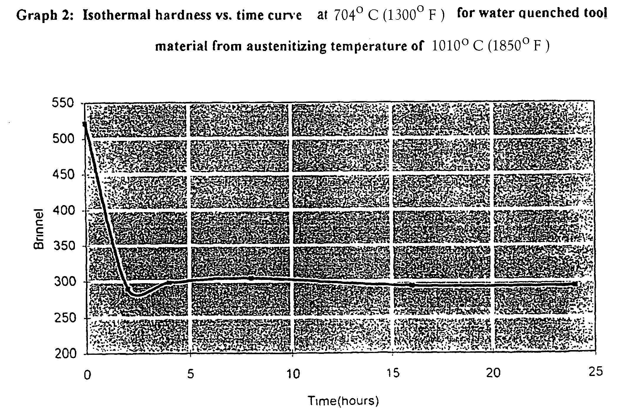
- Two sets of room temperature tensile data were gathered in the short transverse plate direction to gauge the strength and ductility of the tool in a spheroidized condition Yield strength, tensile strength, elongation, and reduction of area data from the tests are listed in Table 10
Tensile properties of heat no. 260686. Stresses are in ksi elongation and reduction of area in percent 0.2% yield stress (ksi) tensile stress (ksi) % elongation in 2.0 inch gauge length % reduction of area in 0.5 inch gauge diameter test 1 101.5 138.5 15.0 39.4 test 2 102.0 140.0 15.5 36.0 -
Tools 11, 12 and 13, and particularlytool 13, when composed of the constituents as above descnbed, will take and hold a high polish during long production runs with the result that rejections traceable to oxidation on the tool will either be eliminated or drastically reduced to an acceptable level over long production runs.
Claims (6)
- A glass molding tool for glass forming operations, said tool having a blemish free surface and being a martensitic stainless steel alloy especially adapted for oxidizing environments having (a) high oxidation resistance, (b) high corrosion resistance, (c) good hot workability, (d) high strength and (e) high wear resistance, said tool having the following composition in weight percent C 0.23 -0.38, Mn 0.40 - 1.00, P 0.040 max, S 0.030 max, Si 0 - 1.20, Ni 1.0 - 3.0, Cr 14.0 - 20.0, Mo 0.25 - 1.00, V 0.10 max, Cu 0.50 - 1.50, Al 0.030 max, Fe balance including incidental impurities
- The glass molding tool of Claim 1 further characterized in that the tool has the following composition in weight percent C .28 - .35, Mn .40 - .60, P .030 max, S .010 max, Si .20 - .50, Ni 1.50 - 1.80, Cr 14.0 - 18.0, Mo .35 - .55, V .02 - .08, Cu .85 - 1.15, Al .02 max, Fe balance including incidental impurities
- A method of producing a glass molding tool for glass molding operations, comprising the steps of forming a melt in an electric furnace,subjecting said melt to a vacuum sufficiently low to decrease the S, H, O and N contents to very low levels,exposing portions of said melt which are remote from the surface to the vacuum by passing a purging gas upwardly through the melt during at least a portion of the time the melt is exposed to said vacuum,further exposing said melt to the heating effect of an alternating current electric heating arc struck directly between said melt and non-consumable electrode means,forming the product of said melt into a tool for glass molding operations, andtreating the product of said foregoing processing steps so that the tool is a martensitic stainless steel alloy especially adapted for glass molding operations in oxidizing environments having (a) high oxidation resistance, (b) high corrosion resistance, (c) good hot workability, (d) high strength, (e) high wear resistance, and (e) the following composition in weight percent C .23 - .38, Mn .40 - 1.00, P .040 max, S .030 max, Si .0 - 1.20, Ni 1.0 - 3.0, Cr 14.0 - 20.0, Mo .25 - 1.00, V .10 max,
Cu .50 - 1.50, Al .030 max, Fe balance including incidental impurities - The method of claim 3 further including the steps ofsolidifying the melt into an electrode following processing of the melt by the vacuum, purging gas and alternating current heating arc,remelting the electrode in a low absolute pressure environment to form an ingot in a cuprous crucible,said ingot having low O, H and N contents and a very low sulphur content
- The method of claim 4 further characterized in thatthe ingot contains less than about .005 sulphur
- The method of claim 4 further characterized in thatthe remelting of the electrode occurs under an operating pressure of less than about 100 microns Hg, andsaid ingot has less than about 1ppm H, less than about 80 ppm N, less than about 25 ppm O, and less than about 0.003 sulphur
Applications Claiming Priority (2)
| Application Number | Priority Date | Filing Date | Title |
|---|---|---|---|
| US833585 | 1997-04-07 | ||
| US08/833,585 US6110300A (en) | 1997-04-07 | 1997-04-07 | Tool for glass molding operations and method of manufacture thereof |
Publications (3)
| Publication Number | Publication Date |
|---|---|
| EP0870849A2 EP0870849A2 (en) | 1998-10-14 |
| EP0870849A3 EP0870849A3 (en) | 1999-10-13 |
| EP0870849B1 true EP0870849B1 (en) | 2001-12-05 |
Family
ID=25264809
Family Applications (1)
| Application Number | Title | Priority Date | Filing Date |
|---|---|---|---|
| EP98302706A Expired - Lifetime EP0870849B1 (en) | 1997-04-07 | 1998-04-07 | Tool for glass molding operations and method of manufacture thereof |
Country Status (7)
| Country | Link |
|---|---|
| US (1) | US6110300A (en) |
| EP (1) | EP0870849B1 (en) |
| JP (1) | JP3045995B2 (en) |
| KR (1) | KR100273871B1 (en) |
| AT (1) | ATE210204T1 (en) |
| CA (1) | CA2233830C (en) |
| DE (1) | DE69802742T2 (en) |
Cited By (1)
| Publication number | Priority date | Publication date | Assignee | Title |
|---|---|---|---|---|
| US8557059B2 (en) | 2009-06-05 | 2013-10-15 | Edro Specialty Steels, Inc. | Plastic injection mold of low carbon martensitic stainless steel |
Families Citing this family (11)
| Publication number | Priority date | Publication date | Assignee | Title |
|---|---|---|---|---|
| US6412308B1 (en) * | 1999-09-20 | 2002-07-02 | Owens-Brockway Glass Container Inc. | Liquid cooling of glassware molds |
| US6689312B2 (en) * | 2001-11-28 | 2004-02-10 | Sg Alternatives, L.L.C. | Alloy composition and improvements in mold components used in the production of glass containers |
| US9770611B2 (en) | 2007-05-03 | 2017-09-26 | 3M Innovative Properties Company | Maintenance-free anti-fog respirator |
| DE102008027682B4 (en) * | 2008-06-10 | 2011-03-17 | Eduard Heidt | Method for producing thin-walled and high-strength components |
| FR2951196B1 (en) * | 2009-10-12 | 2011-11-25 | Snecma | DEGASTING STAINLESS STEEL MARTENSITIC STEELS BEFORE REFUSAL UNDER DICE |
| CN102154592B (en) * | 2011-03-04 | 2012-11-21 | 燕山大学 | Micro-alloying martensite stainless steel for blades of water turbine and manufacturing method thereof |
| CN102242313B (en) * | 2011-07-18 | 2012-12-26 | 山东建筑大学 | High-hardness silver-bearing martensite antibacterial stainless steel |
| CN102994900A (en) * | 2011-09-13 | 2013-03-27 | 常熟市精工模具制造有限公司 | Wear and heat resistant high-chromium glass die |
| UA111115C2 (en) | 2012-04-02 | 2016-03-25 | Ейкей Стіл Пропертіс, Інк. | cost effective ferritic stainless steel |
| GB201421617D0 (en) | 2014-12-04 | 2015-01-21 | 3M Innovative Properties Co | Respirator tab |
| CN110303134A (en) * | 2019-04-11 | 2019-10-08 | 佛山市兰普斯光电科技有限公司 | Fine aluminium manufacturing method of heat radiator |
Family Cites Families (12)
| Publication number | Priority date | Publication date | Assignee | Title |
|---|---|---|---|---|
| US3720545A (en) * | 1971-08-20 | 1973-03-13 | Crucible Inc | Steel mold and method for producing the same |
| US4218243A (en) * | 1972-09-20 | 1980-08-19 | Hitachi Metals, Ltd. | Fully martensitic steel for a metal mold for molding glass and the metal mold |
| US4541862A (en) * | 1982-11-30 | 1985-09-17 | A. Finkl & Sons Co. | Ladle steelmaking method and apparatus |
| US4600427A (en) * | 1984-10-22 | 1986-07-15 | A. Finkl & Sons Co. | Method of ladle steelmaking and product produced thereby |
| JP2580186B2 (en) | 1987-07-18 | 1997-02-12 | 関東特殊製鋼株式会社 | Mold material for plastic injection molding |
| US5089067A (en) * | 1991-01-24 | 1992-02-18 | Armco Inc. | Martensitic stainless steel |
| US5232120A (en) * | 1991-06-04 | 1993-08-03 | 21St Century Containers, Ltd. | Container for bulk liquids and solids |
| JP3228439B2 (en) * | 1992-02-07 | 2001-11-12 | 日立金属株式会社 | Mold steel and press die steel with excellent EDM and machinability |
| US5252120A (en) * | 1992-10-26 | 1993-10-12 | A. Finkl & Sons Co. | Method and apparatus for double vacuum production of steel |
| US5364588A (en) * | 1992-10-26 | 1994-11-15 | A. Finkl & Sons Co. | Double stabilized stainless-type steel die block |
| AUPM593094A0 (en) * | 1994-05-30 | 1994-06-23 | Commonwealth Scientific And Industrial Research Organisation | Tools for the manufacture of glass articles |
| AT405193B (en) * | 1995-01-16 | 1999-06-25 | Boehler Edelstahl | USE OF A CHROMED MARTENSITIC IRON BASED ALLOY FOR PLASTICS |
-
1997
- 1997-04-07 US US08/833,585 patent/US6110300A/en not_active Expired - Lifetime
-
1998
- 1998-04-02 CA CA002233830A patent/CA2233830C/en not_active Expired - Lifetime
- 1998-04-06 JP JP10108458A patent/JP3045995B2/en not_active Expired - Lifetime
- 1998-04-07 EP EP98302706A patent/EP0870849B1/en not_active Expired - Lifetime
- 1998-04-07 DE DE69802742T patent/DE69802742T2/en not_active Expired - Lifetime
- 1998-04-07 AT AT98302706T patent/ATE210204T1/en active
- 1998-04-07 KR KR1019980012183A patent/KR100273871B1/en not_active Expired - Fee Related
Cited By (1)
| Publication number | Priority date | Publication date | Assignee | Title |
|---|---|---|---|---|
| US8557059B2 (en) | 2009-06-05 | 2013-10-15 | Edro Specialty Steels, Inc. | Plastic injection mold of low carbon martensitic stainless steel |
Also Published As
| Publication number | Publication date |
|---|---|
| JP3045995B2 (en) | 2000-05-29 |
| JPH1143744A (en) | 1999-02-16 |
| US6110300A (en) | 2000-08-29 |
| CA2233830C (en) | 2002-03-12 |
| CA2233830A1 (en) | 1998-10-07 |
| EP0870849A2 (en) | 1998-10-14 |
| EP0870849A3 (en) | 1999-10-13 |
| ATE210204T1 (en) | 2001-12-15 |
| KR19980081135A (en) | 1998-11-25 |
| DE69802742D1 (en) | 2002-01-17 |
| KR100273871B1 (en) | 2000-12-15 |
| DE69802742T2 (en) | 2002-06-27 |
Similar Documents
| Publication | Publication Date | Title |
|---|---|---|
| KR100429050B1 (en) | Low alloy steel for the manufacture of moulds for plastics | |
| US6110300A (en) | Tool for glass molding operations and method of manufacture thereof | |
| JP4154623B2 (en) | Weldable and repairable steel used in the manufacture of plastic molds | |
| JP4900127B2 (en) | Induction hardening steel and manufacturing method thereof | |
| US5415711A (en) | High-strength spring steels and method of producing the same | |
| CN115896634B (en) | High-temperature-resistant nonferrous metal die-casting forming die steel material and preparation method thereof | |
| EP1518939B1 (en) | Sulfur free cutting steel for machine structural use | |
| CN115667563A (en) | Precipitation hardening martensitic stainless steel sheet having excellent fatigue resistance | |
| JP3141735B2 (en) | Steel for plastic molding dies | |
| US5279902A (en) | Air hardening steel | |
| US7445750B1 (en) | Reinforced durable steel, method for the production thereof, method for producing parts made of steel, and parts thus obtained | |
| US4318739A (en) | Steel having improved surface and reduction of area transverse properties, and method of manufacture thereof | |
| KR102329951B1 (en) | Plastic injection mold tooling and a method of manufacture thereof | |
| JP2866113B2 (en) | Corrosion resistant mold steel | |
| US6019938A (en) | High ductility very clean non-micro banded die casting steel | |
| KR950007790B1 (en) | Hot rolling tool(mold) steel & the same making method | |
| JP2002363690A (en) | Steel for plastic molding dies | |
| KR910001585B1 (en) | Steel for mold for injection plastic and the method for heat treatment | |
| CN115852272B (en) | Tellurium-containing high-speed steel and preparation method thereof | |
| JP2538905B2 (en) | Steel material for centrifugal casting molds with excellent high temperature strength and toughness | |
| KR100489021B1 (en) | A method for manufacturing high tensile high toughness steel having superior internal quality | |
| JPH04111963A (en) | Production of die steel for plastic working | |
| JPH11158579A (en) | Steel for plastic molding dies | |
| KR910001111B1 (en) | Preharden steel | |
| KR20070117149A (en) | Medium carbon boron steel for vehicle parts with excellent mechanical properties and stable hardening ability |
Legal Events
| Date | Code | Title | Description |
|---|---|---|---|
| PUAI | Public reference made under article 153(3) epc to a published international application that has entered the european phase |
Free format text: ORIGINAL CODE: 0009012 |
|
| AK | Designated contracting states |
Kind code of ref document: A2 Designated state(s): AT DE FR GB IT SE |
|
| AX | Request for extension of the european patent |
Free format text: AL;LT;LV;MK;RO;SI |
|
| PUAL | Search report despatched |
Free format text: ORIGINAL CODE: 0009013 |
|
| AK | Designated contracting states |
Kind code of ref document: A3 Designated state(s): AT BE CH CY DE DK ES FI FR GB GR IE IT LI LU MC NL PT SE |
|
| AX | Request for extension of the european patent |
Free format text: AL;LT;LV;MK;RO;SI |
|
| 17P | Request for examination filed |
Effective date: 20000121 |
|
| AKX | Designation fees paid |
Free format text: AT DE FR GB IT SE |
|
| GRAG | Despatch of communication of intention to grant |
Free format text: ORIGINAL CODE: EPIDOS AGRA |
|
| 17Q | First examination report despatched |
Effective date: 20010329 |
|
| GRAG | Despatch of communication of intention to grant |
Free format text: ORIGINAL CODE: EPIDOS AGRA |
|
| GRAH | Despatch of communication of intention to grant a patent |
Free format text: ORIGINAL CODE: EPIDOS IGRA |
|
| RIN1 | Information on inventor provided before grant (corrected) |
Inventor name: ADAMSON, JESSE Inventor name: UNDERYS, ALGIRDAS A. Inventor name: BRADA, GUY |
|
| GRAH | Despatch of communication of intention to grant a patent |
Free format text: ORIGINAL CODE: EPIDOS IGRA |
|
| GRAA | (expected) grant |
Free format text: ORIGINAL CODE: 0009210 |
|
| AK | Designated contracting states |
Kind code of ref document: B1 Designated state(s): AT DE FR GB IT SE |
|
| REF | Corresponds to: |
Ref document number: 210204 Country of ref document: AT Date of ref document: 20011215 Kind code of ref document: T |
|
| REG | Reference to a national code |
Ref country code: GB Ref legal event code: IF02 |
|
| REF | Corresponds to: |
Ref document number: 69802742 Country of ref document: DE Date of ref document: 20020117 |
|
| ET | Fr: translation filed | ||
| PLBE | No opposition filed within time limit |
Free format text: ORIGINAL CODE: 0009261 |
|
| STAA | Information on the status of an ep patent application or granted ep patent |
Free format text: STATUS: NO OPPOSITION FILED WITHIN TIME LIMIT |
|
| 26N | No opposition filed | ||
| PG25 | Lapsed in a contracting state [announced via postgrant information from national office to epo] |
Ref country code: IT Free format text: LAPSE BECAUSE OF NON-PAYMENT OF DUE FEES Effective date: 20090407 |
|
| PGRI | Patent reinstated in contracting state [announced from national office to epo] |
Ref country code: IT Effective date: 20110616 |
|
| REG | Reference to a national code |
Ref country code: FR Ref legal event code: PLFP Year of fee payment: 19 |
|
| REG | Reference to a national code |
Ref country code: DE Ref legal event code: R082 Ref document number: 69802742 Country of ref document: DE Representative=s name: SR HUEBNER - MUNICH PATENT- UND RECHTSANWALTSP, DE Ref country code: DE Ref legal event code: R082 Ref document number: 69802742 Country of ref document: DE Representative=s name: SR HUEBNER - MUNICH PATENTANWALTSPARTNERSCHAFT, DE Ref country code: DE Ref legal event code: R082 Ref document number: 69802742 Country of ref document: DE Representative=s name: SR HUEBNER & KOLLEGEN, DE |
|
| REG | Reference to a national code |
Ref country code: FR Ref legal event code: PLFP Year of fee payment: 20 |
|
| PGFP | Annual fee paid to national office [announced via postgrant information from national office to epo] |
Ref country code: FR Payment date: 20170224 Year of fee payment: 20 |
|
| PGFP | Annual fee paid to national office [announced via postgrant information from national office to epo] |
Ref country code: DE Payment date: 20170425 Year of fee payment: 20 Ref country code: GB Payment date: 20170428 Year of fee payment: 20 |
|
| PGFP | Annual fee paid to national office [announced via postgrant information from national office to epo] |
Ref country code: IT Payment date: 20170407 Year of fee payment: 20 Ref country code: SE Payment date: 20170411 Year of fee payment: 20 Ref country code: AT Payment date: 20170426 Year of fee payment: 20 |
|
| REG | Reference to a national code |
Ref country code: DE Ref legal event code: R071 Ref document number: 69802742 Country of ref document: DE |
|
| REG | Reference to a national code |
Ref country code: GB Ref legal event code: PE20 Expiry date: 20180406 |
|
| REG | Reference to a national code |
Ref country code: AT Ref legal event code: MK07 Ref document number: 210204 Country of ref document: AT Kind code of ref document: T Effective date: 20180407 |
|
| REG | Reference to a national code |
Ref country code: SE Ref legal event code: EUG |
|
| PG25 | Lapsed in a contracting state [announced via postgrant information from national office to epo] |
Ref country code: GB Free format text: LAPSE BECAUSE OF EXPIRATION OF PROTECTION Effective date: 20180406 |