EP0870679A1 - Package strapping machine - Google Patents
Package strapping machine Download PDFInfo
- Publication number
- EP0870679A1 EP0870679A1 EP98104203A EP98104203A EP0870679A1 EP 0870679 A1 EP0870679 A1 EP 0870679A1 EP 98104203 A EP98104203 A EP 98104203A EP 98104203 A EP98104203 A EP 98104203A EP 0870679 A1 EP0870679 A1 EP 0870679A1
- Authority
- EP
- European Patent Office
- Prior art keywords
- band
- strap
- transducer
- section
- tape
- Prior art date
- Legal status (The legal status is an assumption and is not a legal conclusion. Google has not performed a legal analysis and makes no representation as to the accuracy of the status listed.)
- Granted
Links
Images


Classifications
-
- B—PERFORMING OPERATIONS; TRANSPORTING
- B65—CONVEYING; PACKING; STORING; HANDLING THIN OR FILAMENTARY MATERIAL
- B65B—MACHINES, APPARATUS OR DEVICES FOR, OR METHODS OF, PACKAGING ARTICLES OR MATERIALS; UNPACKING
- B65B13/00—Bundling articles
- B65B13/18—Details of, or auxiliary devices used in, bundling machines or bundling tools
- B65B13/24—Securing ends of binding material
- B65B13/32—Securing ends of binding material by welding, soldering, or heat-sealing; by applying adhesive
- B65B13/322—Friction welding
Definitions
- the invention relates to a device for strapping of packages according to the preamble of the claim 1.
- Vibration welding using a high Frequency driven vibrator is characterized that the transducer in the band closure area one of the two overlapping band sections in high frequency vibrations relative to the other Belt section moves, which creates frictional heat, the areas of the overlapping areas touching each other Sections of tape melt so that they melt together be cohesively connected.
- a used training of the subject of US 4,776,905 provides instead of the button-shaped order its longitudinal axis freely rotatable band clamp this around a distant axis can also be swiveled to arrange. Such a clamp can cross Belt movement of the end of the belt carried by the transducer on a larger radius and therefore a little better but still not follow optimally. Otherwise exist the disadvantages mentioned in the subject of US 4,776,905 here too.
- the device is located in the tape running direction in front of and behind this vibration welding unit, band clamps, which basically allow the strap closure under the tension of the strapped tape, but the tape is in the fastener area all directions more or less heavily loaded.
- band clamps which basically allow the strap closure under the tension of the strapped tape, but the tape is in the fastener area all directions more or less heavily loaded.
- the object of the invention based, a device for strapping packages according to the friction welding process according to the generic term of claim 1 to create a closure training permitted under high belt tensile forces, which is also able to carry relatively small packaged goods strapping high strap tension and at the on complex no additional drives for unit parts can be.
- the invention solves this problem with the features of claim 1 and is characterized accordingly, that the transducer oscillates about an axis, which runs through the movable jaw and that this around the same axis in the same direction as the transducer oscillates, but only from the vibrating band section is carried along.
- the transducer Because the oscillator oscillates around an axis, that runs through the movable jaw, the transducer leads a circular arc around this axis Moving back and forth across a segment of a circle out. Its movement is only at one point in the trajectory oriented perpendicular to the belt longitudinal direction, so that the band section is much less is claimed for shear. If the jaw now according to the same axis according to the same axis the oscillator oscillates, act between the jaw and the band held by her has no relative movements. According to the invention However, the jaw is not driven, it is only carried by the vibrating band section.
- An optimal vibration synchronous carrying of the Jaw is by the vibrating band section according to a further embodiment of the invention especially given when moving Jaw interacting abutment one section of the transducer itself.
- the consequence of this is that the clamping jaw has very high clamping forces can exercise. It is also a very simple one Design realized.
- the friction surface of the Transducer with the opposite surface of one Vibration abutment formed an inclination angle, pointing away from the vibrating axis of the transducer opens in the direction of the tape and has an order of magnitude of approximately 0.3 ° to 1.0 °.
- This will make the different Distance from band sections to the oscillation center in coordination with the pressure forces that occur taken into account in an advantageous manner. From away from the oscillation axis the pressure forces increase increasing vibration path according to the angular inclination continuously. This will be an extraordinary achievement uniform stress on the unit parts and the tape over the length of the closure created away and a completely homogeneous weld.
- the oscillation angle of the transducer is otherwise preferably small and of the order of magnitude from about 4 ° to 5 °.
- the head plate of the Band closure unit is at the end of the hollow shaft attached and cantilevered from there into the strap level a. Because of this conception, the entire tape closure unit from the closure area swing out, with its simple way and Way released the strap loop surrounding the package can be. Also the means of control can be very simple. In this regard the features of claims 8 to 10 of importance.
- a Another particular advantage is that the drive shaft forms a central drive via the all stroke-controlled functional parts of the strap closure unit can be clock controlled.
- a band strapping machine in its entirety is designated by 10 in FIG. 1.
- On your machine frame 11 is a substantially closed Band guide channel 12, through and around with package 13 indicated by dash-dotted lines around a thermoplastic plastic tape 14 one Band closure unit 15 is supplied. Its job consists of overlapping end portions of the around the package 13 led band 14 by means of Friction welding to be welded together by exposure to heat.
- the belt 14 is outside the machine frame 11 on a rotatably mounted tape reel (drum 55) stocked.
- the belt 14 passes through on the machine input side a pair of rollers 16, which two to each other opposite hinge surfaces frictionally has attacking roles that towards each other tensioned and thus held with pressure against the band 14 are.
- the motor drive of this pair of rollers 16 conveys the tape 14 into a tape storage 17, the one such length of tape 14 stored tension-free, such as he at least for the following strapping and for the Distance of the belt 14 to the sealing unit 15 is needed.
- a second pair of rollers 18 is arranged following the tape storage 17 in the tape feed direction. Also the two rollers of this pair of rollers 18 drive the belt 14 frictionally.
- This pair of rollers 18 is reversible driven, because it serves the one shot of the tape 14 in the tape guide channel 12 and, with opposite drive direction, on the other hand that Retraction of the band 14 and its tightening around the package 13. In the latter sense, the pair of rollers is 18th a so-called "low tension clamping device".
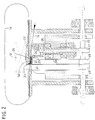
- Fig. 2 illustrates details of the tape lock assembly 15. According to this illustration was the band 14 by means of the weft roller pair 18th through the tension drum 19 and through the belt guide 21 fed through the tape closure unit 15 until the leading end of tape 14 'against a so-called bullet switch 23 ran.
- the strapping process begins itself, after a package 13 has been placed in the channel 12.
- the pair of rollers 18 receives the command to reverse Drive and pulls the tape 14 back, which accordingly the friction forces exerted by the pair of rollers 18 to tighten the package 13 because the first band clamp 25 the front band section 14 ' presses against the lower surface of the head plate 22.
- a cutting knife attached to the weld clamp 27 46 has the length of strap required for strapping separated from the tape supply. Now that's about that Package 13 tightened band 14 in the welding position to form a strap closure.
- FIG. 4 the essential functional parts larger than Fig. 3 shows - mainly characterized by the fact that the front End of band from jaw 25 'of the first band clamp 25 in cooperation with the head plate 22 on the one side of the closure formation zone is held, while the jaw 41 'of the band clamp 41 the other Strap end 14 '' on the other side of the strap closure zone presses against a clamping abutment 42. Every jaw 25 'and 41' thus holds only one band section each firmly, and the overlapping band sections 43 and 44 to be connected together are located in the band closure zone in between.
- the Strap closure zone is from resulting from strapping Belt tension forces kept free.
- the top plate 22 is also a vibrator or Vibrator and about a vertical axis designated 29 driven oscillating.
- the axis of oscillation 29 is at the same time the central axis of the band clamp 25 Clamping jaw 25 'which can rotate freely around this axis is.
- the arrangement is made so that the bearing shaft 30 of the band clamp 25 in a Hollow shaft 31 is guided. 5 and 7 show is the hollow shaft 31 with the oscillating head plate 22 Movementally connected.
- the vibrator 22 is driven by means of a motor 33 flanged to a bearing block 32, a tuning fork 35 via an eccentric shaft 34 drives oscillating, with the hollow shaft 31 rotatably connected is.
- the vibrator 22 performs oscillating Movements around the vertical axis 29. This is shown in Fig. 6, the one end position the swinging motion with solid, the other with dash-dotted lines is shown. Shown is a top view of the transducer 22, the partially erupted to the one below To make jaw 25 'of the band clamp 25 visible.
- the oscillatory movement of the vibrator 22 leads on the one hand the band section 43 on which the Vibrator 22 attacks, relative to that of the weld clamp 27 held opposite band section 44 moved back and forth across a sector of a circle becomes what becomes frictional heat and thereby softening of the mutually facing surfaces of the overlapping Band sections leads.
- the oscillation angle is with about 4 ° to 5 ° small, which is both for protection of the belt and the aggregate parts contributes as itself also reduces wear and noise.
- the band section oscillatingly moved by the oscillator 22 43 is the first of the jaw 25 ' Band clamp 25 also against the bottom of the Vibrator 22 pressed so that the vibrator 22nd oscillating belt section 43 rotatably guided in the hollow shaft 31 of the vibrator 22 Clamping jaw 25 'of the band clamp 25. This will the shear forces acting on the band section 43 kept so low that they are not harmful Effects on a secure closure, including under high belt tension can occur.
- the control of the moving functional parts takes place centrally via a control shaft 45 with control cams 47 for the stroke-controlled band clamp 25, one Control cam 48 for the welding clamp 27 and one Control cam 49 for the second band clamp 41.
Landscapes
- Engineering & Computer Science (AREA)
- Mechanical Engineering (AREA)
- Basic Packing Technique (AREA)
- Package Closures (AREA)
Abstract
Description
Die Erfindung betrifft eine Vorrichtung zum Umreifen von Packstücken nach dem Oberbegriff des Anspruchs 1.The invention relates to a device for strapping of packages according to the preamble of the claim 1.
Das Vibrationsschweißen mittels eines mit hoher Frequenz angetriebenen Schwingers ist dadurch gekennzeichnet, daß der Schwinger im Bandverschlußbereich einen der beiden einander überlappenden Bandabschnitte in hochfrequente Schwingungen relativ zu dem anderen Bandabschnitt bewegt, wodurch Reibungshitze entsteht, die die einander berührenden Flächen der überlappenden Bandabschnitte anschmilzt, so daß diese durch Verschmelzen stoffschlüssig miteinander verbunden werden.Vibration welding using a high Frequency driven vibrator is characterized that the transducer in the band closure area one of the two overlapping band sections in high frequency vibrations relative to the other Belt section moves, which creates frictional heat, the areas of the overlapping areas touching each other Sections of tape melt so that they melt together be cohesively connected.
Aus DE 17 61 166 B1 ist es bekannt, den "Vibrator" genannten Schwinger in Längsrichtung des Bandes schwingen zu lassen. Da der Schwinger gegen die Bandzugkräfte arbeiten muß, lassen sich insbesondere bei nicht oder nur in geringem Maße kompressiblen Packstücken keine hohen Spannkräfte erreichen. Auch sind besonders hohe Antriebskräfte am Schwinger erforderlich. Im übrigen ist die Anordnung so getroffen, daß auf die Verbindungsstelle der überlappenden Bandabschnitte die in der Schlaufe herrschende Zugspannung voll einwirkt, da das Bandmaterial nur zwischen dem Vibrator und von der anderen Bandseite her gegen ihn drückende Greifer eingespannt ist. Diese Art der Bandverschlußausbildung ist sehr verschleißbehaftet. From DE 17 61 166 B1 it is known to use the "vibrator" mentioned vibrators swing in the longitudinal direction of the belt allow. Because the transducer against the tape tensile forces must work, especially when not or only slightly compressible packages none achieve high tension forces. Are also particularly high Driving forces on the transducer required. Furthermore the arrangement is such that the connection point of the overlapping band sections that in the Loop acting fully acts as this Tape material only between the vibrator and from the clamped on the other side of the hinge against him is. This type of strap closure training is very subject to wear.
Bei der Vorrichtung entsprechend US 4,776,905 werden die einander überlappenden Bandabschnitte einseitig neben dem Schwinger fest zusammengepreßt, und der Schwinger bewegt den Bandabschnitt, an dem er angreift, quer zur Bandlängsrichtung über den von einem Gegenhalter dagegen gepreßte zweite Bandabschnitt. Anders als die Oszillation des Schwingers und des ihm zugehörenden Bandendes in Bandlängsrichtung führt diese Querbewegung des Bandes bei der Herstellung des Schweißverschlusses zu einer sehr starken Scherbeanspruchung des vom Schwinger bewegten Bandabschnitts. Dieser kann daher während der Verschlußausbildung insbesondere bei hohen Bandspannungen leicht abreißen.In the device according to US 4,776,905 the overlapping band sections on one side pressed tightly next to the transducer, and the Schwinger moves the section of the tape he is attacking transversely to the longitudinal direction of the tape over that of a counterholder against it pressed second band section. Different to the oscillation of the transducer and that belonging to it This transverse movement leads to the end of the strip in the longitudinal direction of the strip of the tape in the manufacture of the sweat closure to a very strong shear stress from the Swinging band section. This can therefore during closure formation, especially at high Tear off the belt tension easily.
Um diesem Nachteil ansatzweise zu begegnen, ist in der Widerlagerplatte neben dem Schwinger ein knopfförmiger, um eine zum Band lotrecht stehende Achse frei drehbewegliche Klemmkörper angeordnet. Dieser kann jedoch die Querschwingbewegungen des Bandes nur zu einem sehr geringen Teil abfangen, da er nur rotierende Bewegungen im Abstand von dem linaer quer zum Band bewegten Schwinger ausführen kann. Im übrigen besteht bei dieser Reibschweißvorrichtung das Problem eines Bandrisses eher an der von der Klemmeinrichtung abgewandten Seite des Schwingers. Da keine zweite Bandklemme vorgesehen ist, und aufgrund der thermischen Belastung des Bandes während der Verschlußausbildung sind nur geringe Spannkräfte erreichbar.To tackle this disadvantage to some extent, in the abutment plate next to the transducer is a button-shaped, around an axis perpendicular to the belt rotatable clamp body arranged. This can however the transverse vibratory movements of the belt only increase intercept a very small part as it is only rotating Movements at a distance from the linear across the band can perform moving vibrator. Otherwise there is the problem of this friction welding device Band tears rather on the side facing away from the clamping device Side of the transducer. Since no second band clamp is provided and due to the thermal Strain on the belt during the formation of the closure only low clamping forces can be achieved.
Eine benutzte Weiterbildung des Gegenstandes der US 4,776,905 sieht vor, anstelle des knopfförmigen, um seine Längsachse frei drehbaren Bandklemmers diesen um eine entfernt liegende Achse zusätzlich schwenkbeweglich anzuordnen. Ein solcher Klemmer kann der queren Bandbewegung des vom, Schwinger mitgenommenen Bandendes auf einem größeren Radius und daher ein wenig besser, aber immer noch nicht optimal folgen. Im übrigen bestehen die zum Gegenstand der US 4,776,905 genannten Nachteile auch hier.A used training of the subject of US 4,776,905 provides instead of the button-shaped order its longitudinal axis freely rotatable band clamp this around a distant axis can also be swiveled to arrange. Such a clamp can cross Belt movement of the end of the belt carried by the transducer on a larger radius and therefore a little better but still not follow optimally. Otherwise exist the disadvantages mentioned in the subject of US 4,776,905 here too.
Desweiteren ist z.B. aus EP 0 605 759 eine Reibschweißeinrichtung bekanntgeworden, bei der der Schwinger weder in Bandlängsrichtung noch in Bandquerrichtung linear verschieblich vibriert, sondern als Ringscheibe ausgebildet ist, die mit exzentrischem Versatz zu einer lotrecht zur Bandfläche stehenden Achse umläuft. Der vom Schwinger mitgenommene Bandabschnitt wird somit einer Taumel- oder "Schwabbel"-Bewegung unterworfen. In den Ringkörper des Schwingers ist ein lediglich federbelastetes Druckstück integriert, um die Bandenden im Wirkbereich des Schwingers zu führen bzw. gegeneinander zu halten. Bei der entsprechenden, in der Praxis ausgeführten Vorrichtung befinden sich in Bandlaufrichtung vor und hinter dieser Vibrationsschweißeinheit Bandklemmen, die es grundsätzlich erlauben, den Bandverschluß unter der Zugspannung des umreiften Bandes auszuführen, aber das Band wird im Verschlußbereich in alle Richtungen mehr oder weniger stark belastet. Um die auftretenden Scherbeanspruchung der Bandabschnitte zu begrenzen, sind die in EP 0 605 795 A1 nicht dargestellten, bei der praktisch ausgeführten Maschine jedoch vorhandenen Bandklemmen vor und hinter der im Vibrationsverschlußaggregat sehr weit auseinandergesetzt, um lange, frei bewegbare Bandabschnitte zur Verfügung zu haben und deren Dehnung ausnutzen zu können. Daraus resultiert jedoch der Nachteil, daß keine kleinen Packstücke, z.B. Stangenmaterial, umreift werden können.Furthermore, e.g. from EP 0 605 759 a friction welding device became known in which the transducer neither in the longitudinal direction of the belt nor in the transverse direction of the belt vibrates linearly, but as a ring disc is formed with an eccentric offset revolves perpendicular to the belt surface. Of the The belt section taken along by the vibrator is thus subject to a wobble or "wobble" movement. In the ring body of the vibrator is only spring-loaded Pressure piece integrated to the band ends in Leading range of the transducer or against each other to keep. With the corresponding, executed in practice The device is located in the tape running direction in front of and behind this vibration welding unit, band clamps, which basically allow the strap closure under the tension of the strapped tape, but the tape is in the fastener area all directions more or less heavily loaded. Around the occurring shear stress on the belt sections to be limited, those not shown in EP 0 605 795 A1, on the practical machine however existing band clamps in front of and behind the in Vibration lock assembly very far apart, around long, freely movable belt sections to have and to be able to take advantage of their stretch. However, this results in the disadvantage that no small ones Packages, e.g. Bar material to be strapped can.
Auch die DE 40 14 305 C2, von der die vorliegende Erfindung ausgeht, befaßt sich mit dem Problem, die nachteiligen Folgen der Bandbeanspruchung in einem Vibrationsschweißbereich, in dem die miteinander zu verbindenden Bandabschnitte einander überlappen und wobei vor und hinter diesem Verschlußbereich jeweils eine, nur einen Bandabschnitt festhaltende Klemme angeordnet ist. Hier ist die Anordnung so getroffen, daß diejenige Bandklemme, die an dem Bandabschnitt angreift, der vom Schwinger beaufschlagt ist, selbst durch einen maschinellen, aktiven Antrieb synchron mit dem Schwinger angetrieben ist und sich dabei unter Mitnahme des Bandabschnitts parallel zur Schwingbewegung des Schwingers bewegt, wobei diese Schwingbewegung rechtwinklig zur Bandlängsrichtung erfolgt.Also DE 40 14 305 C2, of which the present one Invention is concerned with the problem that adverse consequences of band stress in one Vibration welding area in which the to each other connecting band sections overlap each other and being in front of and behind this closure area arranged a clamp holding only one band section is. Here the arrangement is such that the band clamp on the band section attacked by the transducer itself thanks to a mechanical, active drive in sync with the vibrator is driven and taking it with it of the band section parallel to the swinging movement of the transducer moves, this swinging motion perpendicular to the longitudinal direction of the belt.
Damit die angetriebene Klemmbacke den Bandabschnitt auch wirksam mitnehmen kann, wird dieser auf der der Klemmbacke abgewandten Seite gegen eine glatte Widerlagerfläche gedrückt. Einerseits resultieren hieraus hohe Reibungskräfte und dadurch bedingter Verschleiß, andererseits führt die glatte Oberfläche des Widerlagers naturgemäß zu geringeren Klemmkräften. Dadurch, daß die Klemmbacke aktiv angetrieben ist, ist der maschinelle Aufwand der Vorrichtung groß. So that the driven jaw of the belt section can also take it effectively, this will the side facing away from the jaw against a smooth Abutment surface pressed. On the one hand, this results high friction forces and consequent wear, on the other hand, the smooth surface of the Abutment naturally to lower clamping forces. The fact that the jaw is actively driven the mechanical complexity of the device is large.
Hiervon ausgehend, liegt der Erfindung die Aufgabe zugrunde, eine Vorrichtung zum Umreifen von Packstücken nach dem Reibschweißverfahren entsprechend dem Oberbegriff des Patentanspruches 1 zu schaffen, die eine Verschlußausbildung unter hohen Bandzugkräften gestattet, die ferner in der Lage ist, relativ kleines Packgut mit hoher Bandspannung zu umreifen und bei der auf aufwendige zusätzliche Antriebe für Aggregateteile verzichtet werden kann.Proceeding from this, the object of the invention based, a device for strapping packages according to the friction welding process according to the generic term of claim 1 to create a closure training permitted under high belt tensile forces, which is also able to carry relatively small packaged goods strapping high strap tension and at the on complex no additional drives for unit parts can be.
Die Erfindung löst diese Aufgabe mit den Merkmalen des Anspruches 1 und ist entsprechend dadurch gekennzeichnet, daß der Schwinger um eine Achse oszilliert, die durch die bewegliche Klemmbacke verläuft und daß diese um dieselbe Achse gleichsinnig mit dem Schwinger oszilliert, jedoch lediglich vom schwingenden Bandabschnitt mitgeführt wird.The invention solves this problem with the features of claim 1 and is characterized accordingly, that the transducer oscillates about an axis, which runs through the movable jaw and that this around the same axis in the same direction as the transducer oscillates, but only from the vibrating band section is carried along.
Dadurch, daß der Schwinger um eine Achse oszilliert, die durch die bewegliche Klemmbacke verläuft, führt der Schwinger um diese Achse eine kreisbogenförmige Hin- und Herbewegung über ein Kreissegment hinweg aus. Seine Bewegung ist nur an einem Punkt der Bewegungsbahn senkrecht zur Bandlängsrichtung orientiert, sodaß schon deshalb der Bandabschnitt wesentlich weniger auf Scherung beansprucht wird. Wenn die Klemmbacke nun erfindungsgemäß um dieselbe Achse gleichsinnig mit dem Schwinger oszilliert, wirken zwischen der Klemmbacke und dem von ihr gehaltenen Band keinerlei Relativbewegungen. Entsprechend der Erfindung ist die Klemmbacke jedoch nicht angetrieben, sondern sie wird lediglich vom schwingenden Bandabschnitt mitgeführt. Because the oscillator oscillates around an axis, that runs through the movable jaw, the transducer leads a circular arc around this axis Moving back and forth across a segment of a circle out. Its movement is only at one point in the trajectory oriented perpendicular to the belt longitudinal direction, so that the band section is much less is claimed for shear. If the jaw now according to the same axis according to the same axis the oscillator oscillates, act between the jaw and the band held by her has no relative movements. According to the invention However, the jaw is not driven, it is only carried by the vibrating band section.
Ein Mitführen der Klemmbacke in diesem Sinne war bei dem bisher in Bezug genommenen Stand der Technik nicht vorgesehen.Carrying the jaw in this sense was with the prior art referred to so far not provided.
Eine optimal schwingersynchrone Mitführung der Klemmbacke durch den schwingenden Bandabschnitt ist entsprechend einer weiteren Ausgestaltung der Erfindung insbesondere dann gegeben, wenn das mit der beweglichen Klemmbacke zusammenwirkende Widerlager ein Abschnitt des Schwingers selbst ist. Hieraus ergibt sich der weitere Vorteil, daß sämtliche Flächen von Schwinger und Klemmbacke, die mit Bandflächen in Berührung gelangen, reibungserhöhend ausgebildet, also insbesondere gerauht oder gezahnt sein können, da zwischen diesen einander kontaktierenden Flächen kein Schlupf vorhanden ist. Die Folge hiervon ist, daß die Klemmbacke sehr hohe Klemmkräfte ausüben kann. Außerdem ist eine sehr einfache Bauform realisiert.An optimal vibration synchronous carrying of the Jaw is by the vibrating band section according to a further embodiment of the invention especially given when moving Jaw interacting abutment one section of the transducer itself. This leads to the further one Advantage that all surfaces of transducers and Jaw that comes into contact with band surfaces, designed to increase friction, in particular roughened or can be serrated, because between these one another contacting surfaces there is no slip. The The consequence of this is that the clamping jaw has very high clamping forces can exercise. It is also a very simple one Design realized.
Schwinger und frei bewegliche Klemmbacke lassen sich in besonders günstiger Weise dadurch integrieren, daß der Schwinger am Ende einer Hohlwelle angebracht ist, die die bewegliche Klemmbacke axial verschieblich sowie drehbeweglich lagert.Leave the oscillator and freely movable clamping jaw integrate in a particularly favorable way, that the transducer is attached to the end of a hollow shaft which is the movable jaw axially displaceable as well as rotatable.
Entsprechend einer weiteren Ausgestaltung der Erfindung ist vorgesehen, daß die Reibfläche des Schwingers mit der ihr gegenüberliegenden Fläche eines Schwingerwiderlagers einen Neigungswinkel ausgebildet, der sich von der Schwingachse des Schwingers wegweisend in Bandrichtung öffnet und eine Größenordnung von etwa 0,3° bis 1,0° aufweist. Hierdurch wird der unterschiedlichen Entfernung von Bandabschnitten zum Oszillationszentrum in Abstimmung mit den auftretenden Druckkräften auf vorteilhafte Weise Rechnung getragen. Von der Oszillationsachse weg nehmen die Andruckkräfte bei zunehmendem Schwingweg entsprechend der Winkelneigung kontinuierlich ab. Erreicht werden damit eine außerordentlich gleichmäßige Beanspruchung der Aggregateteile und des Bandes über die Länge des erzeugten Verschlusses hinweg und eine vollkommen homogene Verschweißung.According to a further embodiment of the Invention is provided that the friction surface of the Transducer with the opposite surface of one Vibration abutment formed an inclination angle, pointing away from the vibrating axis of the transducer opens in the direction of the tape and has an order of magnitude of approximately 0.3 ° to 1.0 °. This will make the different Distance from band sections to the oscillation center in coordination with the pressure forces that occur taken into account in an advantageous manner. From away from the oscillation axis the pressure forces increase increasing vibration path according to the angular inclination continuously. This will be an extraordinary achievement uniform stress on the unit parts and the tape over the length of the closure created away and a completely homogeneous weld.
Der Oszillationswinkel des Schwingers ist im übrigen vorzugsweise gering und liegt in der Größenordnung von etwa 4° bis 5°.The oscillation angle of the transducer is otherwise preferably small and of the order of magnitude from about 4 ° to 5 °.
Nach einem weiteren Merkmal der Erfindung bildet der Schwinger die zum Packstück weisende Kopfplatte des Bandverschlußaggregats aus, ist am Ende der Hohlwelle angebracht und kragt von dort aus frei in die Bandumreifungsebene ein. Aufgrund dieser Konzeption läßt sich das gesamte Bandverschlußaggregat aus dem Verschlußbereich herausschwenken, womit auf seine einfache Art und Weise die das Packstück umgebende Bandschlaufe freigegeben werden kann. Auch die Mittel zur Steuerung dazu können sehr einfach ausgeführt sein. Diesbezüglich sind die Merkmale der Ansprüche 8 bis 10 von Bedeutung. Ein besonders wesentlicher Vorteil besteht auch darin, daß die Antriebswelle einen Zentralantrieb ausbildet, über den sämtliche hubgesteuerten Funktionsteile des Bandverschlußaggregats taktgesteuert werden können. According to a further feature of the invention forms the transducer the head plate of the Band closure unit is at the end of the hollow shaft attached and cantilevered from there into the strap level a. Because of this conception, the entire tape closure unit from the closure area swing out, with its simple way and Way released the strap loop surrounding the package can be. Also the means of control can be very simple. In this regard the features of claims 8 to 10 of importance. A Another particular advantage is that the drive shaft forms a central drive via the all stroke-controlled functional parts of the strap closure unit can be clock controlled.
Im übrigen versteht sich die Erfindung am besten aufgrund ihrer nachfolgenden Erläuterung anhand eines in den Zeichnungen dargestellten Ausführungsbeispiels. In den Zeichnungen zeigen:
- Fig. 1
- eine Umreifungsmaschine in schematischer Ansicht,
- Fig. 2
- eine schematische Darstellung des Bandverschlußaggregats in einer ersten Stellung nach dem Einschießen des ein Packstück umgebenden Bandes,
- Fig. 3
- eine der Fig. 2 entsprechende Darstellung des Verschlußaggregats mit um das Packstück herum gestraffter Bandschlaufe,
- Fig. 4
- einen gegenüber Fig. 3 vergrößerte Darstellung nur des Verschlußbereichs der Vorrichtung, wobei zur Verdeutlichung sämtliche Flächenrauhungen nicht dargestellt sind.
- Fig. 5
- einen der Betriebsstellung der Fig. 3 und 4 entsprechenden schematischen Querschnitt durch das Verschlußaggregat im Bereich des Schwingers,
- Fig. 6
- eine vergrößerte Darstellung zur Erläuterung von Geometrie und Funktion von Schwinger und Klemmbacke, und
- Fig. 7
- eine Fig. 4 entsprechende Darstellung der Aggregatstellung am Ende eines Arbeitszyklus.
- Fig. 1
- a strapping machine in a schematic view,
- Fig. 2
- FIG. 2 shows a schematic illustration of the band closure unit in a first position after the band surrounding a package has been shot in, FIG.
- Fig. 3
- 2 shows a representation of the closure unit with a strap loop tightened around the package,
- Fig. 4
- an enlarged view compared to FIG. 3 only the closure area of the device, all surface roughening not being shown for clarity.
- Fig. 5
- 3 and 4 a schematic cross section corresponding to the operating position of FIGS. 3 and 4 through the closure assembly in the area of the oscillator,
- Fig. 6
- an enlarged view to explain the geometry and function of the transducer and jaw, and
- Fig. 7
- a Fig. 4 corresponding representation of the aggregate position at the end of a work cycle.
Eine Bandumreifungsmaschine in ihrer Gesamtheit
ist in Fig. 1 mit 10 bezeichnet. Auf ihrem Maschinengestell
11 befindet sich ein im wesentlichen geschlossener
Bandführungskanal 12, durch den und um ein mit
strichpunktierten Linien angedeutetes Packstück 13
herum ein thermoplastisches Kunststoffband 14 einem
Bandverschlußaggregat 15 zugeführt wird. Dessen Aufgabe
besteht darin, einander überlappende Endabschnitte des
um das Packstück 13 herumgeführten Bandes 14 mittels
Reibschweißen durch Hitzeeinwirkung miteinander zu verschweißen.A band strapping machine in its entirety
is designated by 10 in FIG. 1. On your
Das Band 14 wird außerhalb des Maschinengestells
11 auf einem drehbar gelagerten Bandwickel (Trommel 55)
bevorratet. Zunächst durchläuft das Band 14 maschineneingangsseitig
ein Rollenpaar 16, welches zwei an einander
gegenüberliegenden Bandflächen reibschlüssig
angreifende Rollen aufweist, die aufeinander zu
gespannt und also mit Druck gegen das Band 14 gehalten
sind. Der motorische Antrieb dieses Rollenpaares 16
fördert das Band 14 in einen Bandspeicher 17, der eine
solche Länge von Band 14 spannungsfrei bevorratet, wie
er mindestens für die folgende Umreifung und für die
Wegstrecke des Bandes 14 bis zum Verschlußaggregat 15
benötigt wird.The
In Bandzuführrichtung auf den Bandspeicher 17 folgend
ist ein zweites Rollenpaar 18 angeordnet. Auch die
beiden Rollen dieses Rollenpaares 18 treiben das Band
14 reibschlüssig an. Dieses Rollenpaar 18 ist reversierbar
angetrieben, denn es dient zum einen dem Einschuß
des Bandes 14 in den Bandführungskanal 12 und,
bei entgegengesetzter Antriebsrichtung, zum anderen dem
Rückzug des Bandes 14 und dessen Straffen um das Packstück
13. Im letztgenannten Sinne ist das Rollenpaar 18
eine sog. "Low Tension-Spanneinrichtung".Following the
In Bandzuführrichtung ist dem Einschuß- und Rückzugs-Rollenpaar
18 noch eine "High Tension-Spanneinrichtung"
mittels Spanntrommel 19 nachgeordnet, die
Gegenstand einer anderen Patentanmeldung und hier nicht
weiter von Bedeutung ist. Auf diese Spanntrommel 19
folgen noch eine besondere Bandklemme 20 und ein Führungskanal
21, durch den das Band 14 seinen Weg zum
Bandverschlußaggregat 15 nimmt.In the tape feed direction is the weft and
Fig. 2 veranschaulicht Einzelheiten des Bandverschlußaggregats
15. Entsprechend dieser Darstellung
wurde das Band 14 mittels des Einschußrollenpaares 18
durch die Spanntrommel 19 und durch die Bandführung 21
hindurch dem Bandverschlußaggregat 15 zugeführt, bis
das führende Bandende 14' gegen einen sog. Einschußschalter
23 gelaufen ist.Fig. 2 illustrates details of the
Auf seinem Weg dorthin hat das freie führende
Bandende 14' einen Separatorschlitz 24 in einer ersten
Bandklemme 25 durchlaufen und sodann einen der Bandführung
dienenden Separator 26 innerhalb eines sogenannten
"Schweißklemmers" 27. Die beiden Separatorschlitze dienen
dazu, die Bandabschnitte in ihrem gemeinsamen Überlappungsbereich
(zunächst noch) voneinander fernzuhalten
und ein ungehindertes Abschneiden des unteren
Bandabschnitts zu ermöglichen. On its way there has free leading
Band end 14 'a
Die Betätigung des Einschußschalters 23 durch das
führende, freie Bandende 14' signalisiert der Maschinensteuerung
die Maschinen-Ausgangsstellung und führt
praktisch einen 'Reset' durch. Diese Ausgangsstellung
ist dadurch gekennzeichnet, daß innerhalb des Bandführungskanals
12 (Fig. 1) bereits ein umreifungsfähiger
Abschnitt des Bandes 14 bereitgehalten ist.The actuation of the
Auf sodann durch Knopfdruck eingeleiteten Maschinenbefehl
setzt nun der Umreifungsvorgang selbst ein,
nachdem ein Packstück 13 in den Kanal 12 verbracht ist.
Das Walzenpaar 18 erhält den Befehl zum reversierenden
Antrieb und zieht das Band 14 zurück, welches sich entsprechend
den vom Rollenpaar 18 ausgeübten Friktionskräften
um das Packstück 13 zu straffen beginnt, weil
die erste Bandklemme 25 den vorderen Bandabschnitt 14'
gegen die Unterfläche der Kopfplatte 22 pressend festhält.At the press of a button then initiated machine command
the strapping process begins itself,
after a
Soll das Packstück 13 mit einer höheren Bandspannung
beaufschlagt werden, als sie das "Low Tension"-Walzenpaar
18 dem Band 14 aufprägen kann, schaltet sich
die "High Tension"-Spanntrommel 19 drehend in den Bandspannvorgang
ein und strafft dadurch das Band mit starker
Zugspannung.Should the
Einen solchen gestrafften Bandzustand zeigt
Fig. 3, in der außerdem dargestellt ist, daß der Separator
26 (Fig. 2) aus seiner dortigen Betriebslage
seitlich herausgeschwenkt worden ist, woraufhin der
Schweißklemmer 27 und eine zweite, außen daneben angeordnete
Bandklemme 41 nach oben verlagert worden sind,
die das Band 14 nunmehr auch hier festhält.Such a taut band condition shows
Fig. 3, which also shows that the separator
26 (Fig. 2) from its operating position there
has been swung out sideways, whereupon the
Ein am Schweißklemmer 27 angebrachtes Trennmesser
46 hat die für die Umreifung benötigte Länge an Band
vom Bandvorrat abgetrennt. Nun befindet sich das um das
Packstück 13 gestraffte Band 14 in der Schweißstellung
zur Ausbildung eines Bandverschlusses.A cutting knife attached to the
Diese Stellung ist - entsprechend auch Fig. 4, die
die wesentlichen Funktionsteile größer als Fig. 3 zeigt
- vor allem dadurch gekennzeichnet, daß das vordere
Bandende von der Klemmbacke 25' der ersten Bandklemme
25 im Zusammenwirken mit der Kopfplatte 22 auf der
einen Seite der Verschlußbildungszone festgehalten ist,
während die Klemmbacke 41' der Bandklemme 41 das andere
Bandende 14'' auf der anderen Seite der Bandverschlußzone
gegen ein Klemmwiderlager 42 preßt. Jede Klemmbacke
25' und 41' hält also jeweils nur einen Bandabschnitt
fest, und die einander überlappenden Bandabschnitte
43 und 44, die miteinander zu verbinden sind,
befinden sich in der Bandverschlußzone dazwischen. Die
Bandverschlußzone ist von aus der Umreifung resultierenden
Bandzugkräften freigehalten.This position is - accordingly also Fig. 4, the
the essential functional parts larger than Fig. 3 shows
- mainly characterized by the fact that the front
End of band from jaw 25 'of the
Die Kopfplatte 22 ist zugleich Schwinger oder
Vibrator und um eine mit 29 bezeichnete vertikale Achse
oszillierend angetrieben. Die Oszillationsachse 29 ist
zugleich die zentrale Achse der Bandklemme 25 mit
Klemmbacke 25', die um diese Achse herum frei drehbeweglich
ist. Konkret ist dabei die Anordnung so getroffen,
daß der Lagerschaft 30 der Bandklemme 25 in eine
Hohlwelle 31 geführt ist. Wie Fig. 5 und Fig. 7 zeigen,
ist die Hohlwelle 31 mit der Schwinger-Kopfplatte 22
bewegungseinheitlich verbunden.The
Der Antrieb des Schwingers 22 erfolgt mittels
eines an einem Lagerbock 32 angeflanschten Motors 33,
der über eine Exzenterwelle 34 eine Schwinggabel 35
oszillierend antreibt, mit der die Hohlwelle 31 drehfest
verbunden ist. Somit führt der Schwinger 22 oszillierende
Bewegungen um die vertikale Achse 29 aus. Dies
ist in Fig. 6 dargestellt, wobei die eine Endposition
der Schwingbewegung mit durchgezogenen, die andere mit
strichpunktierten Linien dargestellt ist. Dargestellt
ist eine Aufsicht von oben auf den Schwinger 22, der
teilweise ausgebrochen ist, um die darunter liegende
Klemmbacke 25' der Bandklemme 25 sichtbar zu machen.The
Die Oszillationsbewegung des Schwingers 22 führt
dazu, daß einerseits der Bandabschnitt 43, an dem der
Schwinger 22 angreift, relativ zu dem vom Schweißklemmer
27 festgehaltenen gegenüberliegenden Bandabschnitt
44 auf über einen Kreissektor hinweg hin- und herbewegt
wird, was zur Reibungshitze und dadurch zum Erweichen
der einander zugekehrten Flächen der überlappenden
Bandabschnitte führt. Der Oszillationswinkel ist mit
ca. 4° bis 5° klein gehalten, was sowohl zur Schonung
des Bandes und der Aggregateteile beiträgt als sich
auch verschleiß- und geräuschmindernd auswirkt.The oscillatory movement of the
Zur optimalen Verteilung der Druckkräfte, die während
des Reibschweißvorgangs auftreten, ist die am
Bandabschnitt 44 angreifende Fläche 28 zur Unterfläche
22 des Schwingers, die am Bandabschnitt 43 angreift, um
einen Winkel w geneigt. Der Winkel w, dessen Scheitel
in oder nahe an der Oszillationsachse 29 liegt, öffnet
sich von dort aus über die Klemmstrecke hinweg nach
außen. Durch den Neigungswinkel w, der etwa 0,7°
beträgt, wird eine Abstimmung zwischen Reibweg und
Andruckkraft dahingehend erreicht, daß die Kraft mit
zunehmendem Oszillationsweg, also in Richtung des sich
öffnenden Winkels w, geringfügig kleiner wird. Auch
dies trägt erheblich zur Verschleiß- und Geräuscharmut
der Vorrichtung sowie zu einer homogenen Verschweißung
bei.For the optimal distribution of pressure forces during
of the friction welding process is the
Der vom Schwinger 22 oszillierend bewegte Bandabschnitt
43 wird von der der Klemmbacke 25' der ersten
Bandklemme 25 ebenfalls gegen die Unterseite des
Schwingers 22 gepreßt, so daß der vom Schwinger 22
oszillierend angetriebene Bandabschnitt 43 die drehbeweglich
in der Hohlwelle 31 des Schwingers 22 geführte
Klemmbacke 25' der Bandklemme 25 mitnimmt. Dadurch werden
die auf den Bandabschnitt 43 einwirkenden Scherkräfte
so gering gehalten, daß sie keine schädigenden
Wirkungen auf einen sicheren Verschluß, der auch unter
hoher Bandzugspannung erfolgen kann, ausüben können.The band section oscillatingly moved by the
Nachdem der Bandverschluß in der beschriebenen
Weise hergestellt worden ist, fahren die Bandklemmen 25
und 41 sowie der Schweißklemmer 27 bezüglich der Zeichnungen
wieder nach unten, und sämtliche hubgesteuerten
Einrichtungen des Verschlußaggregats, insbesondere der
Schwinger 22 und die in ihn integrierte Bandklemme 25
werden seitwärts aus der Bandverschlußebene herausgeschwenkt.
Dies zeigt Fig. 7, in der außerdem der zuvor
bereits in die entgegengesetzte Richtung ausgeschwenkten
Separator 26 zu sehen ist.After the tape closure in the described
Has been produced, the band clamps 25 drive
and 41 and the
Die Steuerung der beweglichen Funktionsteile
erfolgt zentral über eine Steuerwelle 45 mit Steuernocken
47 für die hubgesteuerte Bandklemme 25, einem
Steuernocken 48 für den Schweißklemmer 27 und einem
Steuernocken 49 für die zweite Bandklemme 41. Infolge
des Ausschwenkens der Aggregateteile läßt sich das
umreifte Packstück besonders einfach vom Maschinentisch
entfernen.The control of the moving functional parts
takes place centrally via a
Claims (10)
Applications Claiming Priority (2)
| Application Number | Priority Date | Filing Date | Title |
|---|---|---|---|
| DE19714309A DE19714309A1 (en) | 1997-04-08 | 1997-04-08 | Device for strapping packages |
| DE19714309 | 1997-04-08 |
Publications (2)
| Publication Number | Publication Date |
|---|---|
| EP0870679A1 true EP0870679A1 (en) | 1998-10-14 |
| EP0870679B1 EP0870679B1 (en) | 2000-01-26 |
Family
ID=7825693
Family Applications (1)
| Application Number | Title | Priority Date | Filing Date |
|---|---|---|---|
| EP98104203A Expired - Lifetime EP0870679B1 (en) | 1997-04-08 | 1998-03-10 | Package strapping machine |
Country Status (5)
| Country | Link |
|---|---|
| EP (1) | EP0870679B1 (en) |
| AU (1) | AU694711B1 (en) |
| DE (2) | DE19714309A1 (en) |
| ES (1) | ES2144325T3 (en) |
| NZ (1) | NZ330120A (en) |
Cited By (2)
| Publication number | Priority date | Publication date | Assignee | Title |
|---|---|---|---|---|
| WO2003026967A1 (en) * | 2001-09-20 | 2003-04-03 | Cyklop Gmbh | Device for tensioning and sealing tightening straps |
| US6708606B1 (en) | 2002-10-31 | 2004-03-23 | Illinois Tool Works, Inc. | Strapper with improved winder |
Families Citing this family (2)
| Publication number | Priority date | Publication date | Assignee | Title |
|---|---|---|---|---|
| DE10016717C2 (en) * | 2000-04-04 | 2002-11-28 | Conti Temic Microelectronic | Method for positioning and fixing components |
| DE102004027730A1 (en) | 2004-05-07 | 2006-02-23 | Georg Lang | Device for strapping a packaged goods |
Citations (2)
| Publication number | Priority date | Publication date | Assignee | Title |
|---|---|---|---|---|
| GB2055685A (en) * | 1979-08-17 | 1981-03-11 | Hoffmann Cyklop | Welding apparatus for welding overlapping strips of thermoplastic material |
| DE4014305A1 (en) * | 1990-05-04 | 1991-11-07 | Rmo Systempack Gmbh | DEVICE FOR CONNECTING OVERLAPPING SECTIONS OF A THERMOPLASTIC TAPE |
Family Cites Families (6)
| Publication number | Priority date | Publication date | Assignee | Title |
|---|---|---|---|---|
| US3442732A (en) * | 1965-08-13 | 1969-05-06 | Signode Corp | Friction-fusion strap sealing |
| US3442203A (en) * | 1967-04-10 | 1969-05-06 | Signode Corp | Automatic strapping machine employing friction-fused joints |
| US3554845A (en) * | 1967-11-17 | 1971-01-12 | Fmc Corp | Friction welding of plastic strapping |
| US3554846A (en) * | 1968-03-21 | 1971-01-12 | Fmc Corp | Friction welding apparatus |
| US4776905A (en) * | 1986-06-06 | 1988-10-11 | Signode Corporation | Method and apparatus for producing a welded joint in thermoplastic strap |
| US5306383A (en) * | 1992-10-30 | 1994-04-26 | Signode Corporation | Method and apparatus for producing a welded joint in thermoplastic strap with differential pressure |
-
1997
- 1997-04-08 DE DE19714309A patent/DE19714309A1/en not_active Withdrawn
-
1998
- 1998-03-10 DE DE59800086T patent/DE59800086D1/en not_active Expired - Lifetime
- 1998-03-10 EP EP98104203A patent/EP0870679B1/en not_active Expired - Lifetime
- 1998-03-10 ES ES98104203T patent/ES2144325T3/en not_active Expired - Lifetime
- 1998-03-25 AU AU59502/98A patent/AU694711B1/en not_active Ceased
- 1998-04-03 NZ NZ330120A patent/NZ330120A/en unknown
Patent Citations (2)
| Publication number | Priority date | Publication date | Assignee | Title |
|---|---|---|---|---|
| GB2055685A (en) * | 1979-08-17 | 1981-03-11 | Hoffmann Cyklop | Welding apparatus for welding overlapping strips of thermoplastic material |
| DE4014305A1 (en) * | 1990-05-04 | 1991-11-07 | Rmo Systempack Gmbh | DEVICE FOR CONNECTING OVERLAPPING SECTIONS OF A THERMOPLASTIC TAPE |
Cited By (3)
| Publication number | Priority date | Publication date | Assignee | Title |
|---|---|---|---|---|
| WO2003026967A1 (en) * | 2001-09-20 | 2003-04-03 | Cyklop Gmbh | Device for tensioning and sealing tightening straps |
| US7204187B2 (en) | 2001-09-20 | 2007-04-17 | Cyklop Gmbh | Device for tensioning and sealing tightening straps |
| US6708606B1 (en) | 2002-10-31 | 2004-03-23 | Illinois Tool Works, Inc. | Strapper with improved winder |
Also Published As
| Publication number | Publication date |
|---|---|
| ES2144325T3 (en) | 2000-06-01 |
| DE19714309A1 (en) | 1998-10-15 |
| DE59800086D1 (en) | 2000-03-02 |
| EP0870679B1 (en) | 2000-01-26 |
| AU694711B1 (en) | 1998-07-23 |
| NZ330120A (en) | 1999-05-28 |
Similar Documents
| Publication | Publication Date | Title |
|---|---|---|
| DE2658579C2 (en) | Device for automatically tying a package with a thermoplastic tape | |
| DE4018659C2 (en) | Friction welding device for producing a closure on a flexible thermoplastic strapping | |
| DE1536270C2 (en) | Device for tying objects | |
| DE4014305C2 (en) | Device for connecting overlapping sections of a thermoplastic tape | |
| DE2324293C3 (en) | Device for tying a bale or the like | |
| DE2521474C3 (en) | Tensioning and friction welding device for a band made of thermoplastic material wrapping around an object | |
| DE3507142A1 (en) | DEVICE FOR THERMOPLASTIC BAG | |
| EP0064734B1 (en) | Device for applying and tensioning a strap about a package | |
| DE1761166A1 (en) | Bandaging machine and bandaging process | |
| DE2938894C2 (en) | Embroidery machine | |
| CH632205A5 (en) | RETURNING MACHINE FOR FORMING A LOOP A PACKAGE. | |
| EP0870679B1 (en) | Package strapping machine | |
| EP3419810B1 (en) | Strapping device with an ultrasonic welding device | |
| DE1536271B1 (en) | Connection of thermoplastic plastic bands | |
| EP1401710A1 (en) | Knotter hook and cord knotter equipped with the same | |
| EP1002720B1 (en) | Device for connecting the ends of band ties in tying machines | |
| EP0847922B1 (en) | Apparatus for strapping packages | |
| EP1380506B1 (en) | Apparatus and method for strapping goods with a strapping band | |
| DE4422147C2 (en) | Device for connecting end sections of a thermoplastic tape | |
| WO2003000035A1 (en) | Twine knotter | |
| EP3391733B1 (en) | Baling press | |
| DE4121125A1 (en) | FABRIC LAYING MACHINE | |
| EP3391732B1 (en) | Baling press | |
| DE4123923A1 (en) | ADJUSTABLE PACKING MACHINE | |
| EP3391735B1 (en) | Baling press |
Legal Events
| Date | Code | Title | Description |
|---|---|---|---|
| PUAI | Public reference made under article 153(3) epc to a published international application that has entered the european phase |
Free format text: ORIGINAL CODE: 0009012 |
|
| AK | Designated contracting states |
Kind code of ref document: A1 Designated state(s): CH DE ES FR GB IT LI NL |
|
| AX | Request for extension of the european patent |
Free format text: AL;LT;LV;MK;RO;SI |
|
| 17P | Request for examination filed |
Effective date: 19981014 |
|
| 17Q | First examination report despatched |
Effective date: 19981210 |
|
| GRAG | Despatch of communication of intention to grant |
Free format text: ORIGINAL CODE: EPIDOS AGRA |
|
| GRAG | Despatch of communication of intention to grant |
Free format text: ORIGINAL CODE: EPIDOS AGRA |
|
| AKX | Designation fees paid |
Free format text: CH DE ES FR GB IT LI NL |
|
| GRAG | Despatch of communication of intention to grant |
Free format text: ORIGINAL CODE: EPIDOS AGRA |
|
| GRAH | Despatch of communication of intention to grant a patent |
Free format text: ORIGINAL CODE: EPIDOS IGRA |
|
| GRAH | Despatch of communication of intention to grant a patent |
Free format text: ORIGINAL CODE: EPIDOS IGRA |
|
| GRAA | (expected) grant |
Free format text: ORIGINAL CODE: 0009210 |
|
| AK | Designated contracting states |
Kind code of ref document: B1 Designated state(s): CH DE ES FR GB IT LI NL |
|
| REG | Reference to a national code |
Ref country code: CH Ref legal event code: EP |
|
| GBT | Gb: translation of ep patent filed (gb section 77(6)(a)/1977) |
Effective date: 20000127 |
|
| REF | Corresponds to: |
Ref document number: 59800086 Country of ref document: DE Date of ref document: 20000302 |
|
| ET | Fr: translation filed | ||
| ITF | It: translation for a ep patent filed |
Owner name: STUDIO TORTA S.R.L. |
|
| REG | Reference to a national code |
Ref country code: CH Ref legal event code: NV Representative=s name: E. BLUM & CO. PATENTANWAELTE |
|
| REG | Reference to a national code |
Ref country code: ES Ref legal event code: FG2A Ref document number: 2144325 Country of ref document: ES Kind code of ref document: T3 |
|
| PLBE | No opposition filed within time limit |
Free format text: ORIGINAL CODE: 0009261 |
|
| STAA | Information on the status of an ep patent application or granted ep patent |
Free format text: STATUS: NO OPPOSITION FILED WITHIN TIME LIMIT |
|
| 26N | No opposition filed | ||
| REG | Reference to a national code |
Ref country code: GB Ref legal event code: IF02 |
|
| PGFP | Annual fee paid to national office [announced via postgrant information from national office to epo] |
Ref country code: NL Payment date: 20030221 Year of fee payment: 6 |
|
| PGFP | Annual fee paid to national office [announced via postgrant information from national office to epo] |
Ref country code: GB Payment date: 20040303 Year of fee payment: 7 |
|
| PG25 | Lapsed in a contracting state [announced via postgrant information from national office to epo] |
Ref country code: GB Free format text: LAPSE BECAUSE OF NON-PAYMENT OF DUE FEES Effective date: 20050310 |
|
| PG25 | Lapsed in a contracting state [announced via postgrant information from national office to epo] |
Ref country code: NL Free format text: LAPSE BECAUSE OF NON-PAYMENT OF DUE FEES Effective date: 20051001 |
|
| GBPC | Gb: european patent ceased through non-payment of renewal fee |
Effective date: 20050310 |
|
| NLV4 | Nl: lapsed or anulled due to non-payment of the annual fee |
Effective date: 20051001 |
|
| REG | Reference to a national code |
Ref country code: CH Ref legal event code: PFA Owner name: SIGNODE BERNPAK GMBH Free format text: SIGNODE BERNPAK GMBH#MAGNUSSTRASSE 18#D-46535 DINSLAKEN (DE) -TRANSFER TO- SIGNODE BERNPAK GMBH#MAGNUSSTRASSE 18#D-46535 DINSLAKEN (DE) |
|
| REG | Reference to a national code |
Ref country code: CH Ref legal event code: PFA Owner name: ITW PACKAGING SYSTEMS GROUP GMBH, DE Free format text: FORMER OWNER: SIGNODE BERNPAK GMBH, DE |
|
| REG | Reference to a national code |
Ref country code: DE Ref legal event code: R082 Ref document number: 59800086 Country of ref document: DE Representative=s name: ROCHE, VON WESTERNHAGEN & EHRESMANN, DE |
|
| REG | Reference to a national code |
Ref country code: ES Ref legal event code: PC2A Owner name: ITW PACKAGING SYSTEMS GROUP GMBH Effective date: 20140220 |
|
| REG | Reference to a national code |
Ref country code: DE Ref legal event code: R082 Ref document number: 59800086 Country of ref document: DE Representative=s name: ROCHE, VON WESTERNHAGEN & EHRESMANN, DE Effective date: 20140120 Ref country code: DE Ref legal event code: R081 Ref document number: 59800086 Country of ref document: DE Owner name: SPG PACKAGING SYSTEMS GMBH, DE Free format text: FORMER OWNER: SIGNODE BERNPAK GMBH, 46535 DINSLAKEN, DE Effective date: 20140120 Ref country code: DE Ref legal event code: R081 Ref document number: 59800086 Country of ref document: DE Owner name: ITW PACKAGING SYSTEMS GROUP GMBH, DE Free format text: FORMER OWNER: SIGNODE BERNPAK GMBH, 46535 DINSLAKEN, DE Effective date: 20140120 |
|
| REG | Reference to a national code |
Ref country code: FR Ref legal event code: CD Owner name: ITW PACKAGING SYSTEMS GROUP GMBH Effective date: 20140124 |
|
| REG | Reference to a national code |
Ref country code: CH Ref legal event code: PFA Owner name: SPG PACKAGING SYSTEMS GMBH, DE Free format text: FORMER OWNER: ITW PACKAGING SYSTEMS GROUP GMBH, DE |
|
| REG | Reference to a national code |
Ref country code: DE Ref legal event code: R082 Ref document number: 59800086 Country of ref document: DE Representative=s name: ROCHE, VON WESTERNHAGEN & EHRESMANN, DE |
|
| REG | Reference to a national code |
Ref country code: DE Ref legal event code: R082 Ref document number: 59800086 Country of ref document: DE Representative=s name: ROCHE, VON WESTERNHAGEN & EHRESMANN, DE Effective date: 20140922 Ref country code: DE Ref legal event code: R081 Ref document number: 59800086 Country of ref document: DE Owner name: SPG PACKAGING SYSTEMS GMBH, DE Free format text: FORMER OWNER: ITW PACKAGING SYSTEMS GROUP GMBH, 46535 DINSLAKEN, DE Effective date: 20140922 |
|
| REG | Reference to a national code |
Ref country code: FR Ref legal event code: CD Owner name: SPG PACKAGING SYSTEMS GMBH Effective date: 20141002 |
|
| REG | Reference to a national code |
Ref country code: ES Ref legal event code: PC2A Owner name: SPG PACKAGING SYSTEMS GMBH Effective date: 20150210 |
|
| REG | Reference to a national code |
Ref country code: FR Ref legal event code: PLFP Year of fee payment: 19 |
|
| PGFP | Annual fee paid to national office [announced via postgrant information from national office to epo] |
Ref country code: CH Payment date: 20160328 Year of fee payment: 19 Ref country code: ES Payment date: 20160328 Year of fee payment: 19 |
|
| PGFP | Annual fee paid to national office [announced via postgrant information from national office to epo] |
Ref country code: IT Payment date: 20160323 Year of fee payment: 19 |
|
| REG | Reference to a national code |
Ref country code: FR Ref legal event code: PLFP Year of fee payment: 20 |
|
| PGFP | Annual fee paid to national office [announced via postgrant information from national office to epo] |
Ref country code: FR Payment date: 20170327 Year of fee payment: 20 |
|
| PGFP | Annual fee paid to national office [announced via postgrant information from national office to epo] |
Ref country code: DE Payment date: 20170329 Year of fee payment: 20 |
|
| REG | Reference to a national code |
Ref country code: CH Ref legal event code: PL |
|
| PG25 | Lapsed in a contracting state [announced via postgrant information from national office to epo] |
Ref country code: IT Free format text: LAPSE BECAUSE OF NON-PAYMENT OF DUE FEES Effective date: 20170310 Ref country code: LI Free format text: LAPSE BECAUSE OF NON-PAYMENT OF DUE FEES Effective date: 20170331 Ref country code: CH Free format text: LAPSE BECAUSE OF NON-PAYMENT OF DUE FEES Effective date: 20170331 |
|
| REG | Reference to a national code |
Ref country code: DE Ref legal event code: R071 Ref document number: 59800086 Country of ref document: DE |
|
| REG | Reference to a national code |
Ref country code: ES Ref legal event code: FD2A Effective date: 20180507 |
|
| PG25 | Lapsed in a contracting state [announced via postgrant information from national office to epo] |
Ref country code: ES Free format text: LAPSE BECAUSE OF NON-PAYMENT OF DUE FEES Effective date: 20170311 |