EP0869899B1 - Aussenbord antriebswelle mit teilgetauchtem propeller und stabiblisierendem leitwerk - Google Patents
Aussenbord antriebswelle mit teilgetauchtem propeller und stabiblisierendem leitwerk Download PDFInfo
- Publication number
- EP0869899B1 EP0869899B1 EP96917163A EP96917163A EP0869899B1 EP 0869899 B1 EP0869899 B1 EP 0869899B1 EP 96917163 A EP96917163 A EP 96917163A EP 96917163 A EP96917163 A EP 96917163A EP 0869899 B1 EP0869899 B1 EP 0869899B1
- Authority
- EP
- European Patent Office
- Prior art keywords
- shroud
- propeller
- channel
- set forth
- marine outdrive
- Prior art date
- Legal status (The legal status is an assumption and is not a legal conclusion. Google has not performed a legal analysis and makes no representation as to the accuracy of the status listed.)
- Expired - Lifetime
Links
- 230000000087 stabilizing effect Effects 0.000 title 1
- XLYOFNOQVPJJNP-UHFFFAOYSA-N water Substances O XLYOFNOQVPJJNP-UHFFFAOYSA-N 0.000 claims abstract description 49
- 238000011144 upstream manufacturing Methods 0.000 claims description 10
- 230000003247 decreasing effect Effects 0.000 claims description 4
- 230000007423 decrease Effects 0.000 claims description 2
- 239000002184 metal Substances 0.000 claims 1
- 238000012360 testing method Methods 0.000 description 5
- 238000010276 construction Methods 0.000 description 3
- 239000012530 fluid Substances 0.000 description 3
- 239000000446 fuel Substances 0.000 description 3
- 238000009434 installation Methods 0.000 description 3
- 230000001133 acceleration Effects 0.000 description 2
- 230000002411 adverse Effects 0.000 description 2
- 238000013459 approach Methods 0.000 description 2
- 230000000712 assembly Effects 0.000 description 2
- 238000000429 assembly Methods 0.000 description 2
- 230000000694 effects Effects 0.000 description 2
- 230000008030 elimination Effects 0.000 description 2
- 238000003379 elimination reaction Methods 0.000 description 2
- 210000003414 extremity Anatomy 0.000 description 2
- 241000239290 Araneae Species 0.000 description 1
- 229910001369 Brass Inorganic materials 0.000 description 1
- 229920000049 Carbon (fiber) Polymers 0.000 description 1
- 206010035148 Plague Diseases 0.000 description 1
- 241000607479 Yersinia pestis Species 0.000 description 1
- 239000004411 aluminium Substances 0.000 description 1
- XAGFODPZIPBFFR-UHFFFAOYSA-N aluminium Chemical compound [Al] XAGFODPZIPBFFR-UHFFFAOYSA-N 0.000 description 1
- 229910052782 aluminium Inorganic materials 0.000 description 1
- 230000004888 barrier function Effects 0.000 description 1
- 239000010951 brass Substances 0.000 description 1
- 239000004917 carbon fiber Substances 0.000 description 1
- 238000006243 chemical reaction Methods 0.000 description 1
- 230000009977 dual effect Effects 0.000 description 1
- 238000004519 manufacturing process Methods 0.000 description 1
- 239000000463 material Substances 0.000 description 1
- VNWKTOKETHGBQD-UHFFFAOYSA-N methane Chemical compound C VNWKTOKETHGBQD-UHFFFAOYSA-N 0.000 description 1
- 238000000034 method Methods 0.000 description 1
- 229910001220 stainless steel Inorganic materials 0.000 description 1
- 239000010935 stainless steel Substances 0.000 description 1
- 210000001364 upper extremity Anatomy 0.000 description 1
Images


Classifications
-
- B—PERFORMING OPERATIONS; TRANSPORTING
- B63—SHIPS OR OTHER WATERBORNE VESSELS; RELATED EQUIPMENT
- B63H—MARINE PROPULSION OR STEERING
- B63H5/00—Arrangements on vessels of propulsion elements directly acting on water
- B63H5/07—Arrangements on vessels of propulsion elements directly acting on water of propellers
- B63H5/125—Arrangements on vessels of propulsion elements directly acting on water of propellers movably mounted with respect to hull, e.g. adjustable in direction, e.g. podded azimuthing thrusters
-
- B—PERFORMING OPERATIONS; TRANSPORTING
- B63—SHIPS OR OTHER WATERBORNE VESSELS; RELATED EQUIPMENT
- B63H—MARINE PROPULSION OR STEERING
- B63H5/00—Arrangements on vessels of propulsion elements directly acting on water
- B63H5/07—Arrangements on vessels of propulsion elements directly acting on water of propellers
- B63H5/16—Arrangements on vessels of propulsion elements directly acting on water of propellers characterised by being mounted in recesses; with stationary water-guiding elements; Means to prevent fouling of the propeller, e.g. guards, cages or screens
-
- B—PERFORMING OPERATIONS; TRANSPORTING
- B63—SHIPS OR OTHER WATERBORNE VESSELS; RELATED EQUIPMENT
- B63H—MARINE PROPULSION OR STEERING
- B63H1/00—Propulsive elements directly acting on water
- B63H1/02—Propulsive elements directly acting on water of rotary type
- B63H1/12—Propulsive elements directly acting on water of rotary type with rotation axis substantially in propulsive direction
- B63H1/14—Propellers
- B63H1/18—Propellers with means for diminishing cavitation, e.g. supercavitation
- B63H2001/185—Surfacing propellers, i.e. propellers specially adapted for operation at the water surface, with blades incompletely submerged, or piercing the water surface from above in the course of each revolution
-
- B—PERFORMING OPERATIONS; TRANSPORTING
- B63—SHIPS OR OTHER WATERBORNE VESSELS; RELATED EQUIPMENT
- B63H—MARINE PROPULSION OR STEERING
- B63H5/00—Arrangements on vessels of propulsion elements directly acting on water
- B63H5/07—Arrangements on vessels of propulsion elements directly acting on water of propellers
- B63H5/08—Arrangements on vessels of propulsion elements directly acting on water of propellers of more than one propeller
-
- F—MECHANICAL ENGINEERING; LIGHTING; HEATING; WEAPONS; BLASTING
- F02—COMBUSTION ENGINES; HOT-GAS OR COMBUSTION-PRODUCT ENGINE PLANTS
- F02B—INTERNAL-COMBUSTION PISTON ENGINES; COMBUSTION ENGINES IN GENERAL
- F02B61/00—Adaptations of engines for driving vehicles or for driving propellers; Combinations of engines with gearing
- F02B61/04—Adaptations of engines for driving vehicles or for driving propellers; Combinations of engines with gearing for driving propellers
- F02B61/045—Adaptations of engines for driving vehicles or for driving propellers; Combinations of engines with gearing for driving propellers for marine engines
Definitions
- This invention relates to improvements in marine outdrive apparatus of the type using surface piercing propellers.
- FR 762747A discloses a partially submerged screw for propelling a boat but does not disclose a shroud which is supported by a tubular propeller shaft mount.
- a marine outdrive with a surface piercing propeller has a tubular propeller shaft carrier or mount coupled to the transom of a boat by a universal joint in the form of a spherical ball.
- This construction allows the rotatable propeller at the rear end of the shaft rotatably carried by the mount to be shifted by fluid piston and cylinder assemblies into any one of a number of different attitudes with respect to the boat transom.
- the thrust of the marine outdrive itself can be generated and varied as to direction and magnitude, thereby providing great versatility to the outdrive and adapting it for a wide range of speed and other requirements for boats of different sizes.
- the present invention is directed to an improved shroud for attachment to the propeller shaft carrier or mount of a surface piercing marine outdrive apparatus.
- the shroud at least partially encircles the propeller and is located on at least one side of the carrier or mount for the propeller drive shaft.
- the rotation of the propeller blades creates an envelope which is caused by the rotation of the outer end faces of the blades.
- This envelope comes progressively closer to the inner surface of the shroud as the blades rotate and approach a downstream end edge of the shroud. Then, the envelope disengages from the shroud after the blades have passed the downstream end edge of the shroud.
- At an upstream end edge of the shroud there is a relatively wide channel which progressively decreases in width as the central part of the shroud is approached and as the envelope approaches the narrowest parts of the channel.
- the inner surface of the shroud and the envelope define the channel which has the upstream and downstream end edges.
- This channel has a relatively wide, convergent entrance end and a relatively narrow divergent exit end.
- each outdrive will have its own shroud. Moreover, it is possible that, for a boat having dual marine outdrives, it need have only one shroud for one of the marine outdrives, the other outdrive being free of any shroud. In such a case, the stability problem is substantially eliminated because of the presence of the volute on the working shroud.
- the primary object of the present invention is to provide an improved shroud for the rear of the marine outdrive of a boat having a surface piercing propeller wherein the shroud extends partially about from the rear end of the tubular shaft mount for the propeller and is in a position to generate a volute which enhances the performance of the boat.
- Another object of the present invention is to provide an apparatus and method of controlling a boat using a marine outdrive with an improved surface piercing propeller smaller in diameter than a conventional propeller and designed to present outer blade extremities which mate with the inner surface portion of the shroud so that the certain instabilities associated with movements of such a boat over water can be eliminated by the use of the propeller with the shroud when the shroud is adjacent to the propeller shaft mount.
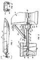
- the shroud of the present invention in a preferred embodiment, is broadly denoted by the numeral 10 and is adapted to be used with a marine outdrive apparatus unit 12 which is attachable to the transom 14 of a boat 16.
- Boat 16 can be of any suitable size and shape and typically it may have a pair of marine outdrive apparatus units 12a secured to and extending rearwardly from the transom 14 of the boat.
- the marine outdrive units may work alone or in unison with each other to produce forward thrust for the boat.
- a marine outdrive unit with which structure is to be used includes a propeller shaft carrier or mount 18 (Fig. 3) having a pivot structure 20, such as a universal ball joint, secured to a support tube 22 attached by spider fasteners 24 to the shroud at the inner, front surface thereby and to mount 18 at several locations.
- Mount 18, therefore, is pivotal relative to support tube 22.
- Mount 18 and tube 22 house a rotatable shaft 30 which is connected through pivot structure 20 to a drive motor 32 mounted in the boat 16 at some suitable location thereon.
- the shaft extends to the rear end of mount 18 and is secured by fasteners 34 to a surface piercing propeller 36 which is rotatable when motor 32 is actuated.
- the propeller is shown connected to shaft 34 in Fig. 6. At least a portion of the propeller is above water level during normal operation of the marine outdrive unit.
- the mount 18 is raised and lowered so as to raise and lower the propeller 36 by the actuation of a first fluid piston cylinder assembly 38 pivotally mounted at its forward end 39a on the transom 14 and secured by a pivot 39b on mount 18 forwardly of the rear end of the mount 18.
- a second fluid piston cylinder assembly 44 is pivotally mounted by a pivot structure 46 on transom 14 and by a pivot structure 48 on mount 18. Changes in the attitude of mount 18 can be made by operating assemblies 38 and 44.
- Shroud 10 of the present invention eliminates these problems.
- the shroud had a hollow interior and works in cooperation with the propeller to increase the load on the propeller blades and generates a volute which is a vortex or scroll-like phenomenon which causes the water to flow rearwardly at a higher velocity that would be the case in the absence of the volute.
- the volute is characterized in accelerating the scroll-like or spiral paths of water rearwardly by the blades rotating about the central axis of the propeller 36.
- the envelope traversed by the outer or rear ends of the blades of the propeller is denoted by the numeral 40 and typically rotates in a circle having a diameter in the range of 254mm (10") to 812.8mm (32"), more particularly 342.9mm (13.5").
- the outer ends of the propeller blades are substantially complemental to the adjacent inner surface portion of the shroud.
- the faces of the blades could be considered flat as to the inner surface of the shroud as they sweep out a somewhat cylindrical space concentric to the concentric to the cylindrical inner wall surface of the shroud as shown in Figs. 5 and 6. It is this substantial flatness and concentricity of the end faces of the blades which provides for maximum loading of the blades with water and thereby the greater acceleration speed of the blades.
- the outer ends of the blades are forwardly of the rear edge of the shroud by a distance in the range of 6.35mm (.25") to 63.5mm (2.5").
- This rotational speed is achieved by causing the blades to enter the circular channel 42 (Fig.4) formed by the inner surface of the shroud 10 and the envelope 40.
- the upstream end 43 of the channel 42 has an entrance opening 44.
- a portion 46 of the shroud from the 7 o'clock position in Fig. 4 to the 9 o'clock position is substantially straight and vertical.
- the channel 42 has a curved part 47 which continues on and merges with the wall portion or at the location past the 12 o'clock position 48.
- the channel extends further outwardly and downwardly and terminates at about the 2 o'clock position spaced outwardly from the envelope 40 of the blades of the propeller.
- the shroud makes a divergent exit opening 50 at the downstream end of the channel. Also noteworthy is the fact that the shroud top part 48 is relatively close to but spaced from the envelope 40 of the blades to form a pinched-off channel segment 51 as spacing or gap which aids in causing the maximum loading of the blades as they enter the channel 48 and as they move towards the minimum spacing 51. Since the water is not compressible, the water is carried on the rear faces of the blades until the water can be accelerated rearwardly, at which time the rearwardly accelerated water generates a relatively high forward thrust force.
- Shroud 10 has a pair of vertically spaced side edges 54 and 56. The side edges are generally parallel with each other as shown in Fig. 5.
- Shroud 10 is made from an imperforate plate or panel from suitable material, such as stainless steel, brass, aluminium or carbon fiber.
- the shroud has an inner surface which is relatively smooth and hollow and is buffed and polished so as to minimise drag on the flow of water past the inner surface of the shroud.
- Shroud 10 has a front edge 62 and a rear edge 64.
- edges 44, 40, 56, 64 and 62 define the boundaries of the shroud.
- the 9 o'clock positions of channel 42 have a width in the range of 12.7mm (0.5") to 38.1mm (1.5"), more nearly 31.75mm (1.25").
- the gap is normally about 6.35mm (.25") for a propeller diameter of 342.9mm (13.5").
- the outer end of the shroud in the vicinity of the 1 o'clock to the 2 o'clock positions is at an angle typically in the range of 15° to 30°, more nearly 25°, as shown in Fig. 4.
- Shroud 10 and propeller shaft 30 typically define a down running angle of about 7° to about 10°.
- bottom edges of shroud 10 are usually disposed at an angle of about 3° to about 7° when viewing from the rear end of the shroud .
- the lower half of shroud 10 is rolled parallel to the horizontal running line so that shroud 10 passes through the water in a substantially straight line.
- the upper outer surface of shroud 10 typically has a running angle substantially parallel to the propeller shaft 30 angle.
- the shroud 10 is mounted on a marine outdrive unit 12, such as the right hand propeller and carrier unit looking forwardly, as shown in Fig. 4.
- a marine outdrive unit 12 such as the right hand propeller and carrier unit looking forwardly, as shown in Fig. 4.
- the propeller drive shaft of unit 12b will typically rotate in a counterclockwise sense when viewing Fig. 4 and the shroud will be facing the opposite direction from that shown in Fig. 4.
- the shaft and propeller will rotate in a counterclockwise sense when viewing Fig. 4.
- the motor 32 will be operated to rotate drive shaft 30. Rotation of the drive shaft 30 will spin the blades 33 of propeller 36 of Fig. 4, in a clockwise sense when viewing Fig. 4.
- the plane of rotation of the rear ends of blades 33 of the propeller 36 is substantially at the rear edge of the envelope 40. At this position, the propeller efficiency is at a maximum, and the efficiency drops off as the blade assembly is at a location forwardly or rearwardly of the envelope.
- Shroud 10 is typically far enough away from the plane of rotation of propeller 36, as shown in Fig. 4, so as to prevent interference by the shroud to the rotation of the propeller itself.
- the inner surfaces of the shroud members also contribute to keeping the center shaft thrust direction stable so that there is no tendency for the propeller to lift out of the water and cause the operator of the boat to fight the steering and trim gears of the boat.
- the system of the present invention has the ability to adjust for offset side loading on a single engine installation if necessary.
- the propeller configuration is different from standard propeller units.
- the present invention has a propeller which is smaller in diameter with wide thick blade tips that make it very strong and efficient. This allows the boat to get on plane quicker and easier and maintains plane when the rpms of the system are decreased. Some conventional boats tend to fall off plane when this occurs; however, with the present system, it is much easier to maintain planing at a lower engine speed.
- the system can be used in many types of installations, such as the following:
- the present invention acts much like a water pump, drawing water into a volute shaped shroud that forces it downwardly into the propeller blade face where it is then converted into thrust.
- the shroud offers protection from propeller exposure and propeller protection such as when backing down near pilings, floats, docks and the like.
- the shroud eliminates the need to built expensive platforms over propellers for protection and peace of mind. By using smaller diameter propellers, this costs is greatly reduced.
- the other aspect of this invention is the newly designed propeller configuration that will enhance the concept.
- the propeller is more like an impeller that a propeller.
- This impeller concept will be stronger and more efficient. It is also less costly to manufacture. Cavitation burns on the propeller face are practically nonexistent. The propeller shaft side loading is decreased.
- Propeller costs can be reduced by use of the propeller of the present invention. For instance, for a 812.8mm (32") conventional propeller, the normal cost is about $6,200. A 609.6mm (24") propeller will do the same work as a 812.8mm (32") conventional propeller. The cost of a 609.6mm (24") propeller is $2,700. The difference between the $6,200 and $2,700 equals a savings of $3,500 that can be realized with a 609.6mm (24") propeller of the present invention versus a 812.8mm (32") conventional propeller.
- a second embodiment of the shroud of the present invention is broadly denoted by the numeral 10a and is shown in Figs. 7A and 7B.
- the shroud 10a does not encircle the mount 18 or the propeller 36. Instead, shroud 10a has a pair of generally parallel side walls 13a and 15a which are relatively straight and extent downwardly from the 9 o'clock and 3 o'clock positions.
- the walls 13a and 15a terminate at lower edges which are below the envelope of the blades, the envelope being denoted by the numeral 40a.
- the shroud 10a is mounted by webs 24a or other suitable structure.
- the web has a curved upper part 43a which is integral with side walls 13a and 15a.
- the curved part has a gap 45a which is approximately 6.35mm (1 ⁇ 4") wide; whereas, the side gap at the upstream end of the channel 47a and the channel downstream portion 49a are in the range of 12.70mm (1 ⁇ 2") to 38.1mm (11 ⁇ 2").
- the entrance end tapers to 6.35mm (1 ⁇ 4") which is a minimum across the major portion of the central curved wall 45a or to the 3 o'clock position at which the space 49a commences to diverge.
- the blades of the propeller 36 in Figs. 7A and 7B are below the envelope 40a.
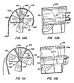
- a third embodiment of the shroud of the present invention is broadly denoted by the numeral 10b and is shown in Figs. 8A and 8B.
- the shroud of Figs. 8A and 8B is substantially the same in construction as shroud 10a of Figs. 7A and &B except that shroud 10n has shorter downstream sidewall 15b than that of shroud 10a (Figs. 7A and 7B).
- shroud 10b has an outer, relatively straight vertical leg 15bb which is at an angle in the range of 60 to 75° to the horizontal with respect to vertical sidewall 15b such that leg 15bb extends partially across the bottom of the shroud as shown in Fig. 8A. All of the dimensions of the shroud 10b are substantially the same as those of shroud 10a.
- Shroud 10b has the blades 33 of the propeller 36 substantially flat at the outer extremities thereof.
- Wall 13b is substantially parallel with wall 15b.
- the entrance and exit channels 47b and 49b are of the same dimensions as the corresponding regions of shroud 10a.
- the pinched-off portion 45b is of a minimum value, such as 6.35mm (1 ⁇ 4").
- a fourth embodiment of the shroud of the present invention is broadly denoted by the numeral 10c and is shown in Figs. 9A and 9B.
- the sidewalls 13c and 15c of shroud 10c are curved as shown in Fig. 9A.
- the side edges 17c and 19c of the shroud are at the same level below and with respect to the central axis of the propeller 36, the central axis being denoted by the numeral 21c.
- the 9:00 o'clock positions and the 3:00 o'clock positions have a gap in the range of 12.7mm (1 ⁇ 2") to 38.1mm (11 ⁇ 2"), more nearly 31.75mm (11 ⁇ 4").
- Shroud 10d has an input channel 10d which tapers to 6.35mm (1 ⁇ 4") gap 41d as the channel extends around the curved part 48d of the upper extremity of the shroud. This gap is for the same purpose as the gaps of the embodiments mentioned above and for all of the embodiments of the shroud.
- webs 24d are provided to mount the shroud 10d in place on mount 18 for rotation about the central axis of rod 30.
- Fig. 11a and 11b show another embodiment of the shroud of named embodiment 10e which is the dame in construction as that of embodiment 10d except that the sidewalls 12e and 14e are spaced outwardly and downwardly from the rotating blades 33 of the propeller 36 such that the channel formed by the rotation of the blades is sufficient to load the blades and to cause the water to be thrust rearwardly so as to provide a forward thrust over the marine outdrive coupled to the shroud.
- the 6.35mm (1 ⁇ 4") gap at the top of the shroud, and all other dimensions are the same as above, is still in place and is common for all of the embodiments of the invention.
Landscapes
- Chemical & Material Sciences (AREA)
- Engineering & Computer Science (AREA)
- Combustion & Propulsion (AREA)
- Mechanical Engineering (AREA)
- Ocean & Marine Engineering (AREA)
- Structures Of Non-Positive Displacement Pumps (AREA)
- Catching Or Destruction (AREA)
- Motor Power Transmission Devices (AREA)
Claims (21)
- Außenbordantrieb (12) für ein Boot (16)dadurch gekennzeichnet,mit einem rohrförmigen Propellerwellenträger (18),mit einer in dem Träger (18) aufgenommenen Welle (30) undmit einem an dem hinteren Ende der Welle (30) für eine Drehung bezüglich des rohrförmigen Propellerwellenträgers (18) befestigbaren Propeller (36),dass der rohrförmige Propellerwellenträger (18) einen Mantel (10) aufweist, der den Propeller (36) wenigstens teilweise umgibt, wenn der Propeller auf der Welle (30) montiert ist und wenn sich die Welle (30) in dem rohrförmigen Propellerwellenträger (18) befindet,dass der Mantel (10) eine Innenfläche hat, die nach außen in einem Abstand von einer von den Enden des Propellers überspannten Rotationshüllkurve (40) aus zur Bildung eines Kanals (42) innerhalb der Innenfläche angeordnet ist,dass der Mantel (10) weiterhin einen tangentialen Abschnitt (46) hat, der im wesentlichen parallel zu einer Tangente an die Rotationshüllkurve (40) ist, unddass der Kanal (42) ein stromaufseitiges Ende (44), ein stromabseitiges Ende (50) und einen Zwischenteil (48) hat,wobei der Kanal (42) in seiner Breite von dem tangentialen Abschnitt (46) des Mantels (10) aus bei Annäherung an den Zwischenteil (48) des Kanals (42) von dem stromaufseitigen Ende (44) aus fortschreitend abnimmt undwobei der Kanal (42) in seiner Breite bei Annäherung an das stromabseitige Ende (50) des Kanals (42) von dem Zwischenteil (48) aus fortschreitend zunimmt.
- Außenbordantrieb (12) nach Anspruch 1, bei welchem sich der Propeller (36) in eine Richtung für ein Pumpen von Wasser durch den Kanal (42) und in Drehrichtung des Propellers (36) dreht.
- Außenbordantrieb (12) nach Anspruch 1, bei welchem der Propeller (36) eine Anzahl von Flügeln (33) hat, von denen jeder eine flache äußere Endfläche aufweist.
- Außenbordantrieb (12) nach Anspruch 3, bei welchem sich die Fläche eines jeden Flügels (33) längs des Trägers (18) erstreckt.
- Außenbordantrieb (12) nach Anspruch 3, bei welchem die Rotationshüllkurve (40) durch die Rotation der äußeren Endflächen der Flügel (33) gebildet wird.
- Außenbordantrieb (12) nach Anspruch 1, bei welchem der Kanal (42) in der Nähe seines stromaufseitigen Endes (44) von einem geraden Segment des Mantels (10) gebildet wird, so dass die Breite des Kanals (42) bei Annäherung an den Zwischenteil (48) des Kanals (42) fortschreitend abnimmt.
- Außenbordantrieb (12) nach Anspruch 1, bei welchem der Mantel (10) an einer Stelle angrenzend an den Zwischenteil (48) gekrümmt ist, wobei sich die Breite des Kanals (42) nahe an dem Zwischenteil (48) auf einem Minimum befindet.
- Außenbordantrieb (12) nach Anspruch 1, bei welchem der Mantel (10) nahe an seinem bezogen auf den Wasserstrom durch den Kanal (42) stromabseitigen Ende einen geraden Teil hat, wodurch die Breite nahe an dem stromabseitigen Ende (50) des Kanals (42) divergiert, wenn das Wasser aus dem Kanal (42) abströmt.
- Außenbordantrieb (12) nach Anspruch 1, bei welchem der Durchmesser des Propellers (30) im Bereich von 254 mm (10") bis 812,8 mm (32") liegt.
- Außenbordantrieb (12) nach Anspruch 1, bei welchem der Mantel (10) aus einer lochfreien Metallplatte hergestellt ist, die mit einem ersten relativ geraden Segment (46), einem zweiten relativ gekrümmten Segment (47) und einem dritten relativ geraden Segment (47a) versehen ist, wobei das erste, zweite und dritte Segment (46, 47, 47a) miteinander ein Stück bilden und sich das erste gerade Segment (46) an dem stromaufseitigen Ende (44) des Kanals (42) befindet und mit der Hüllkurve (40) einen ersten Raum bildet, dessen Breite abnimmt.
- Außenbordantrieb (12) nach Anspruch 10, bei welchem das zweite Segment (47) des Mantels (10) so gekrümmt ist, dass es eine zylindrische Innenfläche bildet.
- Außenbordantrieb (12) nach Anspruch 10, bei welchem das dritte Segment (47a) von der Hüllkurve (40) aus nahe am stromabseitigen Ende (50) des Kanals (42) divergiert.
- Außenbordantrieb (12) nach Anspruch 10, bei welchem der Mantel (10) einen zweiten stromabseitigen Rand hat, der sich in Längsrichtung des Trägers (18) erstreckt und sich in einem Abstand nach außen von der Hüllkurve (40) zur Bildung des stromabseitigen Endes (50) des Kanals (42) befindet.
- Außenbordantrieb (12) nach Anspruch 10, bei welchem der Mantel (10) ein Paar von Seitenrändern (54, 56) angrenzend an das stromaufseitige beziehungsweise stromabseitige Ende (44, 50) des Kanals (42) hat.
- Außenbordantrieb (12) nach Anspruch 10, bei welchem das erste Segment (46) und das dritte Segment (47a) des Mantels (10) sich in der 7 Uhr- beziehungsweise 1 Uhr-Position des Mantels (10) bezogen auf die Drehrichtung des Propellers (36) befinden.
- Außenbordantrieb (12) nach Anspruch 1, bei welchem der Mantel (10) ein hinteres Ende hat und eine obere äußere Fläche mit einem zum Winkel der Propellerwelle (30) parallelen Verlaufswinkel bildet.
- Außenbordantrieb (12) nach Anspruch 1, bei welchem eine minimale Breite des Kanals (42) im Bereich von 6,35 mm (0,25") liegt.
- Außenbordantrieb (12) nach Anspruch 17, bei welchem der Kanalabschnitt einen minimalen Einlass nahe dem gekrümmten zweiten Segment (47) im Bereich von 25,4 mm (1") bis 31,7 mm (1,25") hat.
- Außenbordantrieb (12) nach Anspruch 1, bei welchem der Mantel (10) eine untere Hälfte (50) bildet, die parallel zu einer horizontalen Verlaufslinie so gewalzt ist, dass der Mantel (10) durch das Wasser in einer geraden Linie geht, wobei ein nach unten verlaufender Winkel der Propellerwelle (30) zum Mantel (10) im Bereich von 7° bis 10° liegt und die unteren Ränder des Mantels (10) einen Winkel von 3° bis 7° gesehen vom hinteren Ende des Mantels (10) haben.
- Außenbordantrieb (12) nach Anspruch 10, bei welchem das erste Segment (46) einen abgewinkelten ersten geraden Teil und einen zweiten geraden Teil hat, der an dem ersten geraden Teil befestigt ist, wobei der zweite gerade Teil in das zweite Segment (47) übergeht und das stromabseitige Ende des Kanals nahe der 5 Uhr-Position des Kanals 42 gesehen von seinem hinteren Ende bildet.
- Boot (16) mit einem einen Heckspiegel aufweisenden Rumpf, mit einem Außenbordantrieb (12) nach einem der vorhergehenden Ansprüche, der an dem Heckspiegel (14) festgelegt ist und sich davon aus nach hinten erstreckt, und mit dem Boot (16) verbundenen Einrichtungen (32) zum Drehen der Außenbordantriebswelle (30).
Applications Claiming Priority (3)
| Application Number | Priority Date | Filing Date | Title |
|---|---|---|---|
| US08/482,532 US5667415A (en) | 1995-06-07 | 1995-06-07 | Marine outdrive with surface piercing propeller and stabilizing shroud |
| US482532 | 1995-06-07 | ||
| PCT/US1996/008845 WO1996040550A1 (en) | 1995-06-07 | 1996-06-03 | Marine outdrive with surface piercing propeller and stabilizing shroud |
Publications (3)
| Publication Number | Publication Date |
|---|---|
| EP0869899A1 EP0869899A1 (de) | 1998-10-14 |
| EP0869899A4 EP0869899A4 (de) | 2001-03-14 |
| EP0869899B1 true EP0869899B1 (de) | 2003-11-05 |
Family
ID=23916456
Family Applications (1)
| Application Number | Title | Priority Date | Filing Date |
|---|---|---|---|
| EP96917163A Expired - Lifetime EP0869899B1 (de) | 1995-06-07 | 1996-06-03 | Aussenbord antriebswelle mit teilgetauchtem propeller und stabiblisierendem leitwerk |
Country Status (7)
| Country | Link |
|---|---|
| US (1) | US5667415A (de) |
| EP (1) | EP0869899B1 (de) |
| AU (1) | AU707695B2 (de) |
| CA (1) | CA2223901C (de) |
| DE (1) | DE69630612T2 (de) |
| DK (1) | DK0869899T3 (de) |
| WO (1) | WO1996040550A1 (de) |
Cited By (1)
| Publication number | Priority date | Publication date | Assignee | Title |
|---|---|---|---|---|
| WO2014144063A1 (en) * | 2013-03-15 | 2014-09-18 | Twin Disc, Inc. | Rooster tail suppression apparatus |
Families Citing this family (29)
| Publication number | Priority date | Publication date | Assignee | Title |
|---|---|---|---|---|
| US6234854B1 (en) * | 1998-11-12 | 2001-05-22 | Eric J. Rydzewski | Marine drive assembly |
| US6059618A (en) * | 1998-12-09 | 2000-05-09 | The United States Of America As Represented By The Secretary Of The Navy | Ventilated outboard motor-mounted pumpjet assembly |
| US6045420A (en) | 1999-01-19 | 2000-04-04 | Small; Mark S. | Semi-enclosed surfacing propeller driver system including air induction |
| CA2312253A1 (fr) | 2000-06-15 | 2001-12-15 | Claude Marois | Unite protectrice du propulseur d'une embarcation marine |
| EP1334025B1 (de) * | 2000-11-08 | 2005-08-10 | Fikret Dülger | Achtereinheit für wasserfahrzeug |
| US6431927B1 (en) | 2001-03-23 | 2002-08-13 | Michael W. Sage | Outboard propeller drive system for watercraft |
| US6823812B2 (en) | 2001-05-25 | 2004-11-30 | Von Wolske James P. | Trim tabs and surface drive propeller bite control |
| US6726511B1 (en) | 2001-09-11 | 2004-04-27 | T.J. Brooks Company—division of Hanna Cylinders | Internally ported hydraulic cylinder assembly |
| US6814636B2 (en) * | 2002-11-01 | 2004-11-09 | Greg L. Nolen | Marine radial surface drive |
| EP1572532A1 (de) | 2002-12-03 | 2005-09-14 | Supraventures Ag | Z-antrieb für ein wasserfahrzeug |
| US7143711B1 (en) | 2005-04-07 | 2006-12-05 | Wolske James P Von | Trim tab shape control system |
| US7335074B2 (en) | 2005-06-21 | 2008-02-26 | Howard Arneson | Shroud enclosed inverted surface piercing propeller outdrive |
| EP1780117A1 (de) * | 2005-10-07 | 2007-05-02 | Flexitab S.r.l. | Seeantriebssystem mit teilweise versenkter Schiffsschraube |
| US7631610B1 (en) | 2005-10-19 | 2009-12-15 | Wolske James P Von | Variable area trim tab and means to control water flow along a trim tab and added propeller guard including tunnel propellers |
| EP1803643A1 (de) | 2005-12-30 | 2007-07-04 | Flexitab S.r.l. | Teilgetauchtes Propellersystem für Verdrängungs- und Halbverdrängungsschiffe |
| US7819711B1 (en) | 2006-02-15 | 2010-10-26 | James P. von Wolske | Retractable thrust reversing bucket for boat propeller |
| US7431620B1 (en) * | 2006-05-24 | 2008-10-07 | Harley Howard D | Articulating surface drive |
| US7488226B2 (en) * | 2007-03-08 | 2009-02-10 | Raptor Fishing Technologies, Inc. | Propeller shield apparatus for trolling motor |
| EP1972543A1 (de) | 2007-03-23 | 2008-09-24 | Flexitab S.r.l. | Antriebssystem für einen teilweise tauchenden Propeller |
| DE102007031056B4 (de) * | 2007-07-04 | 2009-04-02 | Mtu Friedrichshafen Gmbh | Verfahren zur Regelung von Schiffantriebsanlagen mit Oberflächenpropellern |
| WO2009069084A2 (en) * | 2007-11-26 | 2009-06-04 | Cape Advanced Engineering (Proprietary) Limited | A propulsion system for a watercraft |
| US9884671B2 (en) | 2009-08-19 | 2018-02-06 | Donald L. Ekhoff | Marine propulsion system and method |
| US8403715B1 (en) | 2011-12-06 | 2013-03-26 | Howard M. Arneson | Marine jet drive |
| USD682186S1 (en) | 2012-02-17 | 2013-05-14 | Arlon J. Gilk | Propeller bearing seal protector |
| USD670229S1 (en) | 2012-02-17 | 2012-11-06 | Gilk Arlon J | Long shaft propeller controller |
| USD670228S1 (en) | 2012-02-17 | 2012-11-06 | Gilk Arlon J | Tubular long shaft propeller |
| US8911272B1 (en) * | 2012-02-17 | 2014-12-16 | Arlon J. Gilk | Long shaft propeller controller and bearing seal protector |
| JP2016159853A (ja) * | 2015-03-04 | 2016-09-05 | ヤンマー株式会社 | 船舶 |
| US9616986B1 (en) | 2015-08-14 | 2017-04-11 | Arlon J. Gilk | Adjustable transom mount |
Family Cites Families (12)
| Publication number | Priority date | Publication date | Assignee | Title |
|---|---|---|---|---|
| FR762747A (fr) * | 1933-08-09 | 1934-04-16 | Dispositif nouveau pour la propulsion des bateaux | |
| JPS5015348Y1 (de) * | 1970-07-08 | 1975-05-13 | ||
| US3768432A (en) * | 1971-10-18 | 1973-10-30 | E Spaulding | Shallow water adaptor for outboard motors |
| US4031846A (en) * | 1975-10-09 | 1977-06-28 | Tone John W | Anti-cavitation shroud and rudder |
| US4645463A (en) | 1980-04-07 | 1987-02-24 | Arneson Howard M | Marine outdrive apparatus |
| DE3042197C2 (de) * | 1980-11-08 | 1984-08-09 | Roland 6729 Neupotz Sand | Antrieb für Wasserfahrzeuge, insbesondere für schnelle Gleitboote |
| JPS5915958A (ja) | 1982-07-19 | 1984-01-27 | Canon Inc | 転写式画像形成装置 |
| IT1185428B (it) * | 1985-10-11 | 1987-11-12 | Rover Marine Srl | Struttura combinata di trasmissione,propulsione ed orientamento,per motoscafi con motore entrobordo |
| US4808132A (en) * | 1986-09-19 | 1989-02-28 | Douglas Geoffrey B | Marine drive apparatus |
| US4909175A (en) | 1988-10-05 | 1990-03-20 | Arnseson Howard M | Boat with trimmable bottom |
| ES2035458T3 (es) * | 1989-07-11 | 1993-04-16 | Roland Sand | Propulsion de bote para botes hidroplanos. |
| CA2022415A1 (en) * | 1990-07-31 | 1992-02-01 | Fred Bohrer | Boat propeller protection device |
-
1995
- 1995-06-07 US US08/482,532 patent/US5667415A/en not_active Expired - Lifetime
-
1996
- 1996-06-03 DK DK96917163T patent/DK0869899T3/da active
- 1996-06-03 DE DE69630612T patent/DE69630612T2/de not_active Expired - Lifetime
- 1996-06-03 EP EP96917163A patent/EP0869899B1/de not_active Expired - Lifetime
- 1996-06-03 CA CA002223901A patent/CA2223901C/en not_active Expired - Lifetime
- 1996-06-03 WO PCT/US1996/008845 patent/WO1996040550A1/en not_active Ceased
- 1996-06-03 AU AU59832/96A patent/AU707695B2/en not_active Ceased
Cited By (1)
| Publication number | Priority date | Publication date | Assignee | Title |
|---|---|---|---|---|
| WO2014144063A1 (en) * | 2013-03-15 | 2014-09-18 | Twin Disc, Inc. | Rooster tail suppression apparatus |
Also Published As
| Publication number | Publication date |
|---|---|
| EP0869899A4 (de) | 2001-03-14 |
| WO1996040550A1 (en) | 1996-12-19 |
| DE69630612T2 (de) | 2004-09-16 |
| DE69630612D1 (de) | 2003-12-11 |
| CA2223901C (en) | 2006-01-17 |
| AU707695B2 (en) | 1999-07-15 |
| US5667415A (en) | 1997-09-16 |
| AU5983296A (en) | 1996-12-30 |
| DK0869899T3 (da) | 2004-03-01 |
| CA2223901A1 (en) | 1996-12-19 |
| EP0869899A1 (de) | 1998-10-14 |
Similar Documents
| Publication | Publication Date | Title |
|---|---|---|
| EP0869899B1 (de) | Aussenbord antriebswelle mit teilgetauchtem propeller und stabiblisierendem leitwerk | |
| JP4299968B2 (ja) | 推進システム | |
| KR100200987B1 (ko) | 선박용 풍동 프로펠러식 젯트추진장치 | |
| US4832642A (en) | Outboard boat propulsion installation | |
| US5720636A (en) | Marine propulsor | |
| US5282763A (en) | Steerable bow thruster for swath vessels | |
| WO2007072185A2 (en) | A propulsion system for a watercraft | |
| JP2025133743A (ja) | マリンダクトプロペラジェット推進システム | |
| EP0219463A1 (de) | Kombinierte Antriebs- und Steuervorrichtung für ein Motorboot mit einem Innenbordmotor | |
| US6024614A (en) | High performance marine propulsion system | |
| WO1992006000A1 (en) | Improvements in or relating to drive units for watercraft | |
| WO1997000198A1 (en) | Arrangement for propulsion of seaborne vessels, especially high speed boats | |
| AU2002350486A1 (en) | Water jet drive for marine vehicles | |
| JPH04501835A (ja) | 船舶推進システムの操舵機構 | |
| US7040941B2 (en) | Vessel propulsion system | |
| US6491554B1 (en) | Watercraft with steerable planing surface | |
| EP0250457A1 (de) | Aussenbordbootantriebsanlage | |
| JP2904789B2 (ja) | 船舶推進機 | |
| RU2840558C1 (ru) | Движительный комплекс объекта в водной среде | |
| WO1993017907A1 (en) | High performance boat prop guard and bracket | |
| Mayville | Marine Jet Drives: Operation and Maintenance |
Legal Events
| Date | Code | Title | Description |
|---|---|---|---|
| PUAI | Public reference made under article 153(3) epc to a published international application that has entered the european phase |
Free format text: ORIGINAL CODE: 0009012 |
|
| 17P | Request for examination filed |
Effective date: 19971223 |
|
| AK | Designated contracting states |
Kind code of ref document: A1 Designated state(s): DE DK FR GB IT |
|
| A4 | Supplementary search report drawn up and despatched |
Effective date: 20010125 |
|
| AK | Designated contracting states |
Kind code of ref document: A4 Designated state(s): DE DK FR GB IT |
|
| RIC1 | Information provided on ipc code assigned before grant |
Free format text: 7B 63H 1/28 A, 7B 63H 5/16 B, 7B 63H 5/12 B |
|
| 17Q | First examination report despatched |
Effective date: 20011214 |
|
| GRAH | Despatch of communication of intention to grant a patent |
Free format text: ORIGINAL CODE: EPIDOS IGRA |
|
| GRAS | Grant fee paid |
Free format text: ORIGINAL CODE: EPIDOSNIGR3 |
|
| GRAA | (expected) grant |
Free format text: ORIGINAL CODE: 0009210 |
|
| AK | Designated contracting states |
Kind code of ref document: B1 Designated state(s): DE DK FR GB IT |
|
| REG | Reference to a national code |
Ref country code: GB Ref legal event code: FG4D |
|
| RIC1 | Information provided on ipc code assigned before grant |
Ipc: 7B 63H 5/16 B Ipc: 7B 63H 1/28 A |
|
| REF | Corresponds to: |
Ref document number: 69630612 Country of ref document: DE Date of ref document: 20031211 Kind code of ref document: P |
|
| REG | Reference to a national code |
Ref country code: DK Ref legal event code: T3 |
|
| ET | Fr: translation filed | ||
| PLBE | No opposition filed within time limit |
Free format text: ORIGINAL CODE: 0009261 |
|
| STAA | Information on the status of an ep patent application or granted ep patent |
Free format text: STATUS: NO OPPOSITION FILED WITHIN TIME LIMIT |
|
| 26N | No opposition filed |
Effective date: 20040806 |
|
| PGFP | Annual fee paid to national office [announced via postgrant information from national office to epo] |
Ref country code: GB Payment date: 20130627 Year of fee payment: 18 Ref country code: DK Payment date: 20130625 Year of fee payment: 18 Ref country code: DE Payment date: 20130627 Year of fee payment: 18 |
|
| PGFP | Annual fee paid to national office [announced via postgrant information from national office to epo] |
Ref country code: IT Payment date: 20130625 Year of fee payment: 18 Ref country code: FR Payment date: 20130702 Year of fee payment: 18 |
|
| REG | Reference to a national code |
Ref country code: DE Ref legal event code: R119 Ref document number: 69630612 Country of ref document: DE |
|
| REG | Reference to a national code |
Ref country code: DK Ref legal event code: EBP Effective date: 20140630 |
|
| GBPC | Gb: european patent ceased through non-payment of renewal fee |
Effective date: 20140603 |
|
| REG | Reference to a national code |
Ref country code: FR Ref legal event code: ST Effective date: 20150227 |
|
| REG | Reference to a national code |
Ref country code: DE Ref legal event code: R119 Ref document number: 69630612 Country of ref document: DE Effective date: 20150101 |
|
| PG25 | Lapsed in a contracting state [announced via postgrant information from national office to epo] |
Ref country code: DE Free format text: LAPSE BECAUSE OF NON-PAYMENT OF DUE FEES Effective date: 20150101 Ref country code: IT Free format text: LAPSE BECAUSE OF NON-PAYMENT OF DUE FEES Effective date: 20140603 |
|
| PG25 | Lapsed in a contracting state [announced via postgrant information from national office to epo] |
Ref country code: FR Free format text: LAPSE BECAUSE OF NON-PAYMENT OF DUE FEES Effective date: 20140630 Ref country code: GB Free format text: LAPSE BECAUSE OF NON-PAYMENT OF DUE FEES Effective date: 20140603 |
|
| PG25 | Lapsed in a contracting state [announced via postgrant information from national office to epo] |
Ref country code: DK Free format text: LAPSE BECAUSE OF NON-PAYMENT OF DUE FEES Effective date: 20140630 |