EP0869873B1 - Fluid applicators - Google Patents
Fluid applicators Download PDFInfo
- Publication number
- EP0869873B1 EP0869873B1 EP96943741A EP96943741A EP0869873B1 EP 0869873 B1 EP0869873 B1 EP 0869873B1 EP 96943741 A EP96943741 A EP 96943741A EP 96943741 A EP96943741 A EP 96943741A EP 0869873 B1 EP0869873 B1 EP 0869873B1
- Authority
- EP
- European Patent Office
- Prior art keywords
- connection part
- applicator
- stem
- fluid
- tip element
- Prior art date
- Legal status (The legal status is an assumption and is not a legal conclusion. Google has not performed a legal analysis and makes no representation as to the accuracy of the status listed.)
- Expired - Lifetime
Links
Images


Classifications
-
- A—HUMAN NECESSITIES
- A46—BRUSHWARE
- A46B—BRUSHES
- A46B5/00—Brush bodies; Handles integral with brushware
- A46B5/002—Brush bodies; Handles integral with brushware having articulations, joints or flexible portions
- A46B5/0054—Brush bodies; Handles integral with brushware having articulations, joints or flexible portions designed to allow relative positioning of the head to body
- A46B5/0062—Brush bodies; Handles integral with brushware having articulations, joints or flexible portions designed to allow relative positioning of the head to body being flexible or resilient during use
- A46B5/0066—Flexible resilience by elastic deformation of the material
-
- A—HUMAN NECESSITIES
- A45—HAND OR TRAVELLING ARTICLES
- A45D—HAIRDRESSING OR SHAVING EQUIPMENT; EQUIPMENT FOR COSMETICS OR COSMETIC TREATMENTS, e.g. FOR MANICURING OR PEDICURING
- A45D40/00—Casings or accessories specially adapted for storing or handling solid or pasty toiletry or cosmetic substances, e.g. shaving soaps or lipsticks
- A45D40/26—Appliances specially adapted for applying pasty paint, e.g. using roller, using a ball
- A45D40/262—Appliances specially adapted for applying pasty paint, e.g. using roller, using a ball using a brush or the like
- A45D40/265—Appliances specially adapted for applying pasty paint, e.g. using roller, using a ball using a brush or the like connected to the cap of the container
-
- A—HUMAN NECESSITIES
- A46—BRUSHWARE
- A46B—BRUSHES
- A46B11/00—Brushes with reservoir or other means for applying substances, e.g. paints, pastes, water
- A46B11/0006—Brushes with reservoir or other means for applying substances, e.g. paints, pastes, water specially adapted to feed the bristle upper surface
-
- A—HUMAN NECESSITIES
- A46—BRUSHWARE
- A46B—BRUSHES
- A46B5/00—Brush bodies; Handles integral with brushware
- A46B5/002—Brush bodies; Handles integral with brushware having articulations, joints or flexible portions
- A46B5/0054—Brush bodies; Handles integral with brushware having articulations, joints or flexible portions designed to allow relative positioning of the head to body
- A46B5/0062—Brush bodies; Handles integral with brushware having articulations, joints or flexible portions designed to allow relative positioning of the head to body being flexible or resilient during use
-
- B—PERFORMING OPERATIONS; TRANSPORTING
- B43—WRITING OR DRAWING IMPLEMENTS; BUREAU ACCESSORIES
- B43L—ARTICLES FOR WRITING OR DRAWING UPON; WRITING OR DRAWING AIDS; ACCESSORIES FOR WRITING OR DRAWING
- B43L19/00—Erasers, rubbers, or erasing devices; Holders therefor
- B43L19/0018—Erasers, rubbers, or erasing devices; Holders therefor with fluids
-
- A—HUMAN NECESSITIES
- A46—BRUSHWARE
- A46B—BRUSHES
- A46B2200/00—Brushes characterized by their functions, uses or applications
- A46B2200/20—Brushes for applying products to surfaces in general
Definitions
- This invention relates to applicators used to apply a fluid substance onto a surface.
- the invention is principally concerned with, and is specially described herein in relation to applicators for applying a correction fluid to a paper surface to facilitate the correction of typing or writing mistakes.
- It is known to supply correction fluid in a bottle provided with a cap which incorporates an applicator having a rigid stem extending from the underside of the cap, and an application element, most often a brush, carried at the free end of the stem.
- the brush By holding the cap, the brush can be dipped into the fluid contained in the bottle to pick up a small portion of the fluid, and by applying the brush to the surface of a sheet of paper a fairly broad band or stripe of correction fluid can be deposited onto the paper.
- the cap When not in use, the cap is secured to the bottle, e.g. by a screw threaded connection, and the applicator is conveniently stored within the bottle.
- the known applicators of this kind work well.
- U.S. patent 2314539 discloses an applicator for applying fluid to a surface where the applicator includes a tip element extending from a flexible part.
- U.S. Patent 2314539 further discloses that the applicator tip is secured to the end of a fluid container neck and the flexible part has an inner duct leading to an outlet port through which fluid inside the container may be dispensed.
- U.S. Patent 2282406 proposes a fluid control applicator that utilizes a sponge tip element attached to the inside of a bottle neck such that when the bottle neck is inverted fluid inside the container is absorbed by the sponge element and can then be blotted onto an application surface.
- British reference GB-A-775009 discloses a spreader type liquid applicator in which a spreading portion is flexibly connected to a ring portion, which can be attached to a dispenser, such that as the spreading portion is wiped across an application surface the dispenser pours or spills applicator fluid ahead of the spreading portion.
- French reference FR-A-1269178 discloses an applicator consisting of a stem extending into a flat applicator tip with the other end of the stem extending from the underside of a bottle cap.
- the Figures of FR-A-1269178 are directed at various stem cross sections which provide surface area for fluid to drain down from onto the applicator tip element.
- French reference FR 682,638 discloses a pen-type applicator wherein an applicator tip is held tight against a hole in the tip of the pen by a flexible member attached to a stem within the pen reservoir. When the applicator tip is forced away from the tip fluid from within the reservoir flows onto a surface to be spread by the applicator tip.
- U.S. 2,291,676 and U.S. 2,397,080 each disclose a spreader-type applicator in which a flexible rubber material is secured to a rigid wooden stem such that the flexible applicator has no resiliency.
- an applicator for applying a fluid to a surface, said applicator having a connection part, a tip at one end of said connection part adapted to be dipped into a fluid to be applied to a surface, the other end of said connection part being connected to one end of a substantially rigid stem, characterized in that said one end of said connection part supports an applicator tip element, and in that the junction between said stem and said connection part provides a hinge such that said connection part is capable of resiliently flexing about said stem as said applicator tip element is stroked across said surface.
- an applicator for applying a fluid to a surface
- said applicator having a connection part, a tip at one end of said connection part adapted to be dipped into a fluid to be applied to a surface, the other end of said connection part being connected to one end of a substantially rigid stem, characterized in that said one end of said connection part supports an applicator tip element, in that the junction between said stem and said connection part provides a hinge such that said connection part is capable of resiliently flexing about said stem as the applicator tip element is stroked across said surface and in that the end of said stem remote from said connection part depends from the underside of a cap, whereby said stem, said tip element and said connection part are positioned within a bottle when said cap is engaged thereon.
- a correction fluid product including a bottle, defining a reservoir and an opening, a correction fluid within the reservoir, and an applicator, inserted through the opening, the applicator including a cap, a connection part and a porous absorbent applicator tip element, characterized in that the applicator includes a substantially rigid elongated stem extending from the cap, the connection part is located at a terminal end of the stem and has a length that is less than the length of the elongated stem, the applicator tip element is connected to an end of the stem by the connection part, the junction between the stem and the connection part provides a hinge between the stem and an end of the applicator tip element such that the connection part is capable of flexing resiliently as the applicator tip element is stroked across a paper surface, which allows the applicator tip element to be deflected from a normal position in which the applicator tip element is substantially aligned with the stem to a position substantially perpendicular to the normal position.
- the application element should be capable of absorbing a portion of fluid when dipped into a body of the fluid, e.g. contained in a bottle, and of holding this fluid portion until the application element is applied to a surface.
- the application element is conveniently formed as a pad or a molded member of porous material e.g. foam, which can be attached in various ways, e.g. by means of adhesive, heat welding or mechanical fixing, to the resiliently flexible connection part. It is also possible for the application element to be made of porous material and to be formed integrally with the resiliently flexible part.
- the resiliently flexible part can be integral with the stem or it can be a separate part fixedly secured to the stem, e.g. by a root portion thereof being inserted into a bore provided in the end of the stem.
- the resiliently flexible part may be capable of flexing in any direction, or it can be adapted e.g. in the manner of a living hinge, to define a predetermined axis about which the application element can pivot relative to the stem while being restrained against deflection in other directions.
- the resiliently flexible connection part preferably allows the application element to deflect from a position substantially aligned with the stem to a position substantially at 90° thereto.
- the application element When the application element is applied to a surface with a natural stroking action, which varies the angle at which the stem is inclined to the surface, there is a tendency to increase the force with which the application element presses against the surface.
- the application element can deflect due to the resiliency of the connection part, and the force against the paper does not vary greatly throughout the stroke. As a consequence the rate at which fluid is delivered onto the surface at the end of the stroke is not substantially different from that at the beginning of the stroke and a uniform stripe of fluid is obtained.
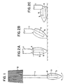
- the correction fluid applicator shown in Figures 1 and 2 comprises a substantially rigid stem 1 attached to and projecting axially from the underside of a correction fluid bottle cap 2. At the lower end of the stem is a connection part 3 which is formed integrally with the stem.
- connection part includes a waisted section 4 of reduced diameter defining a flexing point about which a lower portion of this part is able to deflect resiliently between a normal position axially aligned with the stem (condition (a) in Fig. 2) to a position substantially at 90° to the stem (condition (c) in Fig.2).
- Fixed onto the connection part 3 is an application element in the form of a moulded tip member 5 of open cell foam which can be any required shape, e.g. with a pointed tip or with a flat blade-like edge.
- the foam tip member can be secured in any convenient manner, such as by adhesive.
- the tip member In use, the tip member is dipped into a body of correction fluid and absorbs some of the fluid.
- the connection part 3 flexes causing the tip member to deflect progressively from the normal in line position in accordance with the sequence (a)-(b)-(c) shown in Figure 2.
- the connection part 3 and tip member 5 When the applicator is lifted from the surface at the end of the stroke, the connection part 3 and tip member 5 revert to their in-line positions due to the resilience of the material of the connection part. This resilience also ensures that the tip member is pressed with an even force against the paper thereby, assisting in delivering fluid from the tip member at a constant rate when the tip member is stroked across a paper surface.
- connection part is formed as a separate component and fastened to the end of the stem 1.
- connection part includes a root 6 or peg which is fitted into and secured in a blind bore provided at the end of the stem.
- FIGS 4-7 show another applicator with a separate connection part fixed to the stem 1 in the same way as described in connection with Figure 3.
- the connection part 3 has a generally flat blade section 8 around the free end edge of which a pad 9 of open cell foam is wrapped to form an application element.
- the blade section includes a pair of opposed notches 10 in its side edges which define a flexing point at which the section will flex resiliently with respect to the stem. Due to the flat shape, the flexure occurs about a pivot axis, like a living hinge, the foam pad 9 being supported against movement relative to the stem in directions other than about the pivot axis.
- the notches 10 also serve to locate and retain a collar or monofilament 11 tied around the foam pad to secure it to the connection part. Of course other methods of fixing could be used to secure the foam pad.
- the applicator of Figs. 4-6 functions in essentially the same way as that of Figs. 1-2, although the applicator in this instance needs to be oriented so that the pivotal axis about which flexing can occur is transverse to the direction of displacement of the foam pad application element over the paper surface.
- the foam pad is aligned with the stem as indicated in Fig. 7(a), and at the end of a full stroke it will be at about 90° to the initial position, as shown in Fig.7 (b).
- Figures 8-11 illustrate an applicator in which the resiliently flexible connection part consists of a straight rod 12 of rubber-like material, or suitably resilient plastics, such as sintered ethylene vinyl acetate.
- the cross-section of the rod is not important and it may be conveniently circular, square or rectangular.
- One end of the rod acts as a root inserted into a bore formed in the end of the rigid stem 1, and staked in position by a pin 13 inserted transversely through the stem and rod.
- the projecting portion of the rod is capable of flexing resiliently through about 90° as depicted in Figs. 9(a) and 9(b).
- the application element Carried on the projecting portion of the rod is the application element which can be of any convenient form such a pad 14 or sock of open cell foam secured on the rod by adhesive or by a mechanical fixing means.
- the foam application element can be of any desirable shape, such as rounded as in Fig. 10 or more pointed as in Fig. 11.
- Figs. 12 and 13 are of the same general construction as those Figs. 8-11, but differs in that the application element 15 and the resiliently flexible rod 12 which connects to the stem are made in one piece, such as a sintered ethylene vinyl acetate moulding or casting.
- Figs. 13 (a) and (b) illustrate the flexibility and indicate that the application element can be deflected to a position approximately 90° to the normal position aligned with stem.
- applicators according to the invention can be used for other purposes, e.g. applying cosmetics or make-up.
- Providing for resilient deflection of the application element allows pressure to be applied without causing the application element to splay open, as occurs with the bristles of a brush.
- Applying a uniform film of fluid has the further advantage that the drying time is substantially constant for all portions of the film.
- the deflection of the application element can improve visibility and hence accuracy in use of the applicator.
Description
However with an applicator according to the invention, the application element can deflect due to the resiliency of the connection part, and the force against the paper does not vary greatly throughout the stroke. As a consequence the rate at which fluid is delivered onto the surface at the end of the stroke is not substantially different from that at the beginning of the stroke and a uniform stripe of fluid is obtained.
Claims (12)
- An applicator for applying a fluid to a surface, said applicator having a connection part (3), a tip at one end of said connection part (3) adapted to be dipped into a fluid to be applied to a surface, the other end of said connection part (3) being connected to one end of a substantially rigid stem (1), characterized in that said one end of said connection part (3) supports an applicator tip element (5), and in that the junction between said stem (1) and said connection part (3) provides a hinge (4) such that said connection part (3) is capable of resiliently flexing about said stem (1) as said applicator tip element (5) is stroked across said surface.
- An applicator according to claim 1, characterized in that the end of the stem (1) remote from the connection part (3) depends from the underside of a cap (2), whereby said stem (1), the tip element (5) and said connection part (3) are positioned within a bottle when said cap (2) is engaged thereon.
- An applicator according to claim 1 or claim 2, characterized in that the connection part (3) allows the applicator tip element (5) to be deflected from a normal position substantially aligned with the stem (1) to a position at about 90° to said normal position.
- An applicator to any of claims 1 to 3, characterized in that the connection part (3) defines an axis about which the applicator tip element (5) is pivotable relative to the stem (1).
- An applicator according to any of claims 1 to 4, characterized in that the connection part (3) permits deflection of the applicator tip element (5) only in a single plane containing the longitudinal axis of the stem (1).
- An applicator according to claim 4 or 5, characterized in that the connection part (3) includes a substantially flat section.
- An applicator according to claim 1 or 2, characterized in that the connection part (3) includes a rod (12) of resiliently flexible material.
- An applicator according to any of the preceding claims, characterized in that the connection part (3) is integral with the stem (1).
- An applicator according to any of claims 1 to 7, characterized in that the connection part (3) includes a root portion (6) fixed in a bore in the end of the stem (1).
- An applicator according to any of claims 1 to 9, characterized in that the applicator tip element (5) includes a foam member attached to the connection part (3).
- An applicator according to any of the preceding claims, characterized in that the applicator tip element (5) is made of porous material and is integrally formed with the connection part (3).
- A correction fluid product including a bottle, defining a reservoir and an opening, a correction fluid within the reservoir, and an applicator according to any of claims 2 to 11, inserted through the opening.
Applications Claiming Priority (3)
| Application Number | Priority Date | Filing Date | Title |
|---|---|---|---|
| GBGB9525696.2A GB9525696D0 (en) | 1995-12-15 | 1995-12-15 | Fluid applicators |
| GB9525696 | 1995-12-15 | ||
| PCT/US1996/019885 WO1997021554A1 (en) | 1995-12-15 | 1996-12-12 | Fluid applicators |
Publications (2)
| Publication Number | Publication Date |
|---|---|
| EP0869873A1 EP0869873A1 (en) | 1998-10-14 |
| EP0869873B1 true EP0869873B1 (en) | 2004-02-25 |
Family
ID=10785507
Family Applications (1)
| Application Number | Title | Priority Date | Filing Date |
|---|---|---|---|
| EP96943741A Expired - Lifetime EP0869873B1 (en) | 1995-12-15 | 1996-12-12 | Fluid applicators |
Country Status (13)
| Country | Link |
|---|---|
| EP (1) | EP0869873B1 (en) |
| JP (1) | JP4005133B2 (en) |
| CN (1) | CN1093046C (en) |
| AR (1) | AR001526A1 (en) |
| AU (1) | AU1290197A (en) |
| BR (1) | BR9611963A (en) |
| CA (1) | CA2240175A1 (en) |
| CO (1) | CO4650058A1 (en) |
| DE (1) | DE69631685T2 (en) |
| GB (1) | GB9525696D0 (en) |
| PL (1) | PL327148A1 (en) |
| TR (1) | TR199801103T2 (en) |
| WO (1) | WO1997021554A1 (en) |
Families Citing this family (15)
| Publication number | Priority date | Publication date | Assignee | Title |
|---|---|---|---|---|
| US6227737B1 (en) | 1995-12-15 | 2001-05-08 | The Gillette Company | Fluid applicators |
| US6312180B1 (en) * | 1998-04-23 | 2001-11-06 | The Gillette Company | Applicator for correction fluid |
| JP2001197932A (en) * | 2000-01-18 | 2001-07-24 | Shiseido Co Ltd | Cosmetic container having spatula |
| US7077592B2 (en) | 2002-02-19 | 2006-07-18 | L'oreal S.A. | Applicator including an applicator element configured to apply substance to skin |
| FR2836031B1 (en) * | 2002-02-19 | 2004-11-26 | Oreal | APPLICATOR COMPRISING AN APPLICATION ELEMENT CONFIGURED FOR APPLYING A PRODUCT TO THE SKIN |
| FR2858529B1 (en) * | 2003-08-04 | 2006-02-17 | Oreal | APPLICATOR AND DEVICE FOR PACKAGING AND APPLICATION COMPRISING SUCH AN APPLICATOR |
| MY154822A (en) | 2008-02-27 | 2015-07-31 | Widetech Mfg Sdn Bhd | Correction fluid applicator with foam tip |
| FR2933281B1 (en) * | 2008-07-02 | 2011-12-30 | Oreal | EYELINER APPLICATOR |
| JP6249272B2 (en) * | 2013-09-02 | 2017-12-20 | フィグラ株式会社 | Cosmetic application body |
| JP6394131B2 (en) * | 2014-07-09 | 2018-09-26 | 花王株式会社 | Cosmetic applicator |
| KR102105182B1 (en) * | 2017-08-18 | 2020-04-27 | (주)더페이스샵 | A Cosmetic Device |
| KR102153904B1 (en) * | 2018-11-08 | 2020-09-09 | (주)아모레퍼시픽 | Cosmetic apllication device and cosmeic including the same |
| CN112568580A (en) * | 2019-09-27 | 2021-03-30 | 信桓科斯特股份有限公司 | Eyeliner with coating part capable of bending in multiple directions |
| CN111114175B (en) * | 2020-02-10 | 2021-02-26 | 天津齐康美环保科技有限公司 | Pen type dust-free automatic eraser |
| JP2022045013A (en) * | 2020-09-08 | 2022-03-18 | 株式会社 資生堂 | Cosmetics application tool |
Family Cites Families (10)
| Publication number | Priority date | Publication date | Assignee | Title |
|---|---|---|---|---|
| FR641045A (en) * | 1927-09-16 | 1928-07-26 | Office moisturizer | |
| US1828485A (en) * | 1928-07-30 | 1931-10-20 | William Y Allen | Applicator for dispensing liquids from containers |
| FR682638A (en) * | 1929-10-02 | 1930-05-30 | Improvements to inking devices | |
| US2291676A (en) * | 1939-05-01 | 1942-08-04 | Franklin B Baker | Applicator for adhesives |
| US2282406A (en) * | 1940-03-01 | 1942-05-12 | Ernest L Hollenbeck | Fluid control applicator |
| US2314539A (en) * | 1941-08-05 | 1943-03-23 | Ernest L Hollenbeck | Fluid control applicator |
| US2397080A (en) * | 1943-03-19 | 1946-03-26 | Franklin B Baker | Applicator for adhesives |
| GB775009A (en) * | 1953-09-28 | 1957-05-15 | Hugo Dachinger | Improvements in or connected with liquid adhesive or other viscous liquid dispensers |
| FR1269178A (en) * | 1960-06-28 | 1961-08-11 | Pallet cap for glue or similar bottle | |
| DE59202957D1 (en) * | 1991-01-22 | 1995-08-24 | Kores Holding Zug Ag | DEVICE FOR APPLYING CORRECTION LIQUID. |
-
1995
- 1995-12-15 GB GBGB9525696.2A patent/GB9525696D0/en active Pending
-
1996
- 1996-12-11 AR ARP960105607 patent/AR001526A1/en unknown
- 1996-12-12 DE DE69631685T patent/DE69631685T2/en not_active Expired - Lifetime
- 1996-12-12 BR BR9611963A patent/BR9611963A/en not_active Application Discontinuation
- 1996-12-12 AU AU12901/97A patent/AU1290197A/en not_active Abandoned
- 1996-12-12 PL PL96327148A patent/PL327148A1/en unknown
- 1996-12-12 WO PCT/US1996/019885 patent/WO1997021554A1/en active IP Right Grant
- 1996-12-12 CA CA 2240175 patent/CA2240175A1/en not_active Abandoned
- 1996-12-12 CN CN96199050A patent/CN1093046C/en not_active Expired - Fee Related
- 1996-12-12 TR TR1998/01103T patent/TR199801103T2/en unknown
- 1996-12-12 EP EP96943741A patent/EP0869873B1/en not_active Expired - Lifetime
- 1996-12-12 JP JP52223097A patent/JP4005133B2/en not_active Expired - Fee Related
- 1996-12-16 CO CO96065924A patent/CO4650058A1/en unknown
Also Published As
| Publication number | Publication date |
|---|---|
| DE69631685T2 (en) | 2004-07-22 |
| JP2000501668A (en) | 2000-02-15 |
| WO1997021554A1 (en) | 1997-06-19 |
| AR001526A1 (en) | 1997-11-26 |
| TR199801103T2 (en) | 1998-09-21 |
| MX9804753A (en) | 1998-10-31 |
| GB9525696D0 (en) | 1996-02-14 |
| CO4650058A1 (en) | 1998-09-03 |
| CN1204283A (en) | 1999-01-06 |
| BR9611963A (en) | 1999-05-18 |
| AU1290197A (en) | 1997-07-03 |
| EP0869873A1 (en) | 1998-10-14 |
| DE69631685D1 (en) | 2004-04-01 |
| PL327148A1 (en) | 1998-11-23 |
| CN1093046C (en) | 2002-10-23 |
| JP4005133B2 (en) | 2007-11-07 |
| CA2240175A1 (en) | 1997-06-19 |
Similar Documents
| Publication | Publication Date | Title |
|---|---|---|
| US6227737B1 (en) | Fluid applicators | |
| EP0869873B1 (en) | Fluid applicators | |
| US2982987A (en) | Spreaders for liquids and semi-liquids | |
| US6592282B2 (en) | Cosmetic applicator for fluid material | |
| US7650893B2 (en) | Device for applying a hair product | |
| US7077592B2 (en) | Applicator including an applicator element configured to apply substance to skin | |
| US5888005A (en) | Capillary dosing unit with terminal slit | |
| JPH09510119A (en) | Product dispenser with large attachment / dispensing surface that does not dispense product | |
| US6095705A (en) | Fluid applicator | |
| KR20030069118A (en) | An applicator including an applicator element configured to apply a substance to the skin | |
| WO1997006962A3 (en) | Device for applying liquids onto a base using an applicator element | |
| US6099184A (en) | Dispenser-applicator assembly | |
| US4198172A (en) | Angled ball tip for viscous fluids | |
| WO2004043198A3 (en) | Applicator for scalp medicine | |
| CA2101118A1 (en) | Combination caulking tube cap and applicator device | |
| GB2140675A (en) | Applicator | |
| EP0331843A1 (en) | Adhesive dispensers | |
| US20060249168A1 (en) | Angular-edged nail polish applicators | |
| US6626331B2 (en) | Grout sealant applicator | |
| US5415488A (en) | Shaving cream dispenser | |
| US4617949A (en) | Scalp applicator | |
| US4894948A (en) | Hand held apparatus for selective application of liquid herbicide | |
| US3100314A (en) | Applicator for pasty material | |
| FI58301C (en) | LIMUTMATNINGSANORDNING | |
| JPS6236553Y2 (en) |
Legal Events
| Date | Code | Title | Description |
|---|---|---|---|
| PUAI | Public reference made under article 153(3) epc to a published international application that has entered the european phase |
Free format text: ORIGINAL CODE: 0009012 |
|
| 17P | Request for examination filed |
Effective date: 19980710 |
|
| AK | Designated contracting states |
Kind code of ref document: A1 Designated state(s): DE ES FR GB IT |
|
| 17Q | First examination report despatched |
Effective date: 19980930 |
|
| RAP1 | Party data changed (applicant data changed or rights of an application transferred) |
Owner name: BEROL CORPORATION |
|
| GRAP | Despatch of communication of intention to grant a patent |
Free format text: ORIGINAL CODE: EPIDOSNIGR1 |
|
| GRAS | Grant fee paid |
Free format text: ORIGINAL CODE: EPIDOSNIGR3 |
|
| GRAA | (expected) grant |
Free format text: ORIGINAL CODE: 0009210 |
|
| AK | Designated contracting states |
Kind code of ref document: B1 Designated state(s): DE ES FR GB IT |
|
| PG25 | Lapsed in a contracting state [announced via postgrant information from national office to epo] |
Ref country code: IT Free format text: LAPSE BECAUSE OF FAILURE TO SUBMIT A TRANSLATION OF THE DESCRIPTION OR TO PAY THE FEE WITHIN THE PRE;WARNING: LAPSES OF ITALIAN PATENTS WITH EFFECTIVE DATE BEFORE 2007 MAY HAVE OCCURRED AT ANY TIME BEFORE 2007. THE CORRECT EFFECTIVE DATE MAY BE DIFFERENT FROM THE ONE RECORDED.SCRIBED TIME-LIMIT Effective date: 20040225 Ref country code: FR Free format text: LAPSE BECAUSE OF FAILURE TO SUBMIT A TRANSLATION OF THE DESCRIPTION OR TO PAY THE FEE WITHIN THE PRESCRIBED TIME-LIMIT Effective date: 20040225 |
|
| REG | Reference to a national code |
Ref country code: GB Ref legal event code: FG4D |
|
| REF | Corresponds to: |
Ref document number: 69631685 Country of ref document: DE Date of ref document: 20040401 Kind code of ref document: P |
|
| PG25 | Lapsed in a contracting state [announced via postgrant information from national office to epo] |
Ref country code: ES Free format text: LAPSE BECAUSE OF FAILURE TO SUBMIT A TRANSLATION OF THE DESCRIPTION OR TO PAY THE FEE WITHIN THE PRESCRIBED TIME-LIMIT Effective date: 20040605 |
|
| PG25 | Lapsed in a contracting state [announced via postgrant information from national office to epo] |
Ref country code: GB Free format text: LAPSE BECAUSE OF NON-PAYMENT OF DUE FEES Effective date: 20041212 |
|
| PLBE | No opposition filed within time limit |
Free format text: ORIGINAL CODE: 0009261 |
|
| STAA | Information on the status of an ep patent application or granted ep patent |
Free format text: STATUS: NO OPPOSITION FILED WITHIN TIME LIMIT |
|
| EN | Fr: translation not filed | ||
| 26N | No opposition filed |
Effective date: 20041126 |
|
| GBPC | Gb: european patent ceased through non-payment of renewal fee |
Effective date: 20041212 |
|
| PGFP | Annual fee paid to national office [announced via postgrant information from national office to epo] |
Ref country code: DE Payment date: 20111229 Year of fee payment: 16 |
|
| REG | Reference to a national code |
Ref country code: DE Ref legal event code: R119 Ref document number: 69631685 Country of ref document: DE Effective date: 20130702 |
|
| PG25 | Lapsed in a contracting state [announced via postgrant information from national office to epo] |
Ref country code: DE Free format text: LAPSE BECAUSE OF NON-PAYMENT OF DUE FEES Effective date: 20130702 |