EP0867607A1 - Groupe turbopropulseur double corps à regulation isodrome - Google Patents
Groupe turbopropulseur double corps à regulation isodrome Download PDFInfo
- Publication number
- EP0867607A1 EP0867607A1 EP98400700A EP98400700A EP0867607A1 EP 0867607 A1 EP0867607 A1 EP 0867607A1 EP 98400700 A EP98400700 A EP 98400700A EP 98400700 A EP98400700 A EP 98400700A EP 0867607 A1 EP0867607 A1 EP 0867607A1
- Authority
- EP
- European Patent Office
- Prior art keywords
- propeller
- turboprop
- gas generator
- high pressure
- low
- Prior art date
- Legal status (The legal status is an assumption and is not a legal conclusion. Google has not performed a legal analysis and makes no representation as to the accuracy of the status listed.)
- Granted
Links
- 230000033228 biological regulation Effects 0.000 title description 5
- 239000003638 chemical reducing agent Substances 0.000 claims description 62
- 238000011144 upstream manufacturing Methods 0.000 claims description 7
- 230000000712 assembly Effects 0.000 claims 1
- 238000000429 assembly Methods 0.000 claims 1
- 230000001105 regulatory effect Effects 0.000 claims 1
- 239000007789 gas Substances 0.000 description 45
- 238000005086 pumping Methods 0.000 description 7
- 230000007423 decrease Effects 0.000 description 3
- 208000031968 Cadaver Diseases 0.000 description 2
- 238000002485 combustion reaction Methods 0.000 description 2
- 230000000694 effects Effects 0.000 description 1
- 239000000446 fuel Substances 0.000 description 1
- 230000009347 mechanical transmission Effects 0.000 description 1
Images



Classifications
-
- F—MECHANICAL ENGINEERING; LIGHTING; HEATING; WEAPONS; BLASTING
- F02—COMBUSTION ENGINES; HOT-GAS OR COMBUSTION-PRODUCT ENGINE PLANTS
- F02C—GAS-TURBINE PLANTS; AIR INTAKES FOR JET-PROPULSION PLANTS; CONTROLLING FUEL SUPPLY IN AIR-BREATHING JET-PROPULSION PLANTS
- F02C7/00—Features, components parts, details or accessories, not provided for in, or of interest apart form groups F02C1/00 - F02C6/00; Air intakes for jet-propulsion plants
- F02C7/36—Power transmission arrangements between the different shafts of the gas turbine plant, or between the gas-turbine plant and the power user
-
- F—MECHANICAL ENGINEERING; LIGHTING; HEATING; WEAPONS; BLASTING
- F02—COMBUSTION ENGINES; HOT-GAS OR COMBUSTION-PRODUCT ENGINE PLANTS
- F02C—GAS-TURBINE PLANTS; AIR INTAKES FOR JET-PROPULSION PLANTS; CONTROLLING FUEL SUPPLY IN AIR-BREATHING JET-PROPULSION PLANTS
- F02C3/00—Gas-turbine plants characterised by the use of combustion products as the working fluid
- F02C3/04—Gas-turbine plants characterised by the use of combustion products as the working fluid having a turbine driving a compressor
- F02C3/107—Gas-turbine plants characterised by the use of combustion products as the working fluid having a turbine driving a compressor with two or more rotors connected by power transmission
- F02C3/113—Gas-turbine plants characterised by the use of combustion products as the working fluid having a turbine driving a compressor with two or more rotors connected by power transmission with variable power transmission between rotors
Definitions
- the present invention relates to a turboprop double body whose architecture is particularly suitable to a regulation which keeps the speed of rotation of the propeller.
- Conventional double-body turboprop aircraft include generally low pressure and high rotor groups pressure with independent rotation, each group comprising a compressor and a turbine driving this compressor, the low pressure compressor pumping at least partially into the high pressure compressor and the low pressure turbine being mounted in series with the high pressure turbine; the low pressure rotor group is also connected to a propeller not variable to train it.
- This architecture is ill-suited to a regulation which keeps the propeller rotation speed constant because it entails a risk of pumping of the low compressor pressure at low engine operating speeds.
- the compressor speed high pressure is reduced while the low compressor pressure continues to rotate at high speed. This situation can give rise to flow conditions unstable in compressors and low compressor pressure tends to pump.
- the object of the invention is to solve this problem and achieve a turboprop double body of different architecture adapted to a regulation which keeps the speed of rotation constant the propeller without causing a risk of pumping compressors.
- the invention consists in training at least one propeller by at least the high pressure body of the generator gas double body of the turboprop.
- propeller also applies to fast propellers known as English from propfan.
- the double-body turboprop unit with isodrome regulation with a double gas generator bodies respectively at low and high pressure, and at least a propeller, and each body comprising a compressor and a turbine driving this compressor, is characterized in that the propeller is driven at least by the high pressure body of the gas generator.
- the propeller can be placed at the front of the turboprop engine and upstream from the gas generator, or else can be placed between the low and high pressure compressors of the gas generator and around a speed reducer assembly.
- the propeller is driven only by the high pressure body of the gas generator.
- the propeller is replaced by a doublet of counter-rotating propellers driven respectively by the high and low pressure bodies of the gas generator.
- the propeller is jointly driven by the high and low pressure bodies of the gas generator by means of a torque reducer reduction assembly.
- the double body turboprop shown schematically in FIGS. 1 to 4 include a propeller, or a propfan, with variable pitch driven by the upper body pressure from a double body gas generator.
- the propeller is arranged at the front of the engine and upstream of the gas generator; in Figure 4, the propeller is arranged around the gas generator.
- the gas generator includes a compressor low pressure 1 connected to an annular air inlet 2.
- the output of the low pressure compressor is connected to a channel 3 ring which then divides into several separate channels 4 to allow the passage of the exhaust gas pipes 5 (a single tube is shown in FIG. 1 for reasons of clarity).
- Separate channels 4 meet then to form a new annular channel 6 comprising a first bend 7 at its downstream end connected to a high pressure compressor 8.
- the direction of gas flow reverses 180 degrees.
- the compressed air passes into an annular combustion chamber 9 which feeds in hot gases the turbines 10, 11 for driving compressors, respectively high pressure and low pressure.
- the high pressure turbine 10 also drives propeller or propfan 12 via a reduction gear 13, as well as the equipment (not shown) of the engine and airplane.
- the reducer is intended to reduce the propeller or propfan rotation speed.
- the turbine low pressure is followed by an annular exhaust channel gas 14 which then divides into several tubes 5 (one only tube is shown in Figure 1). Tubes 5 cross separate channels 4 with a second bend in which the direction of gas flow is reversed again 180 degrees.
- the tubes 5 then meet to form an annular enclosure or two lateral nozzles 16 which allow the ejection of the burnt gases.
- the shafts 17, 18 for driving high pressure and low pressure bodies are coaxial.
- Low pressure and high pressure compressors can possibly be fitted with variable-timing stators.
- Figure 2 is a first variant of a group turboprop with the same architecture as that shown in Figure 1.
- the elements identical to those shown in Figure 1 have the same references digital.
- the air inlet 20 of the gas generator is not annular but located under the turboprop nacelle and direction of gas flow in the gas generator is reversed from the figure 1.
- the geometric arrangement of the high pressure body in upstream of the low pressure body avoids crossing the body low pressure by the body high pressure and allows to have a shorter high pressure shaft than the turboprop shown in figure 1.
- FIG. 3 represents a second alternative embodiment of a turboprop group comprising a propeller, or a propfan, 30 variable pitch driven by the high pressure body of a double body gas generator.
- This second variant differs from Figures 1 and 2 by the makes that the high and low pressure shafts 25, 26 which drive the high pressure and low pressure bodies respectively are not coaxial.
- the gas flow does not undergo any inversion of direction and takes place between an air inlet 31 located at the front of the engine and an ejection nozzle 40 located at the rear of the engine.
- low pressure compressors 32 and high pressure 34 possibly fitted with stators variable timing and interconnected by an annular channel 33 ; an annular combustion chamber 35; of a turbine high pressure 36 which drives the high pressure compressor 34, propeller or propfan 30 through a reducer 37, as well as the equipment (not shown) of the engine and aircraft; a low pressure turbine 39 which drives the low pressure compressor, the low turbines and high pressure being connected by an annular channel 38; and an ejection nozzle 40.
- Figure 4 shows a third variant of a turboprop with a propeller, or a propfan, 12 with variable pitch driven by the upper body pressure from a double body gas generator.
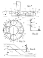
- the propeller 12, or the propfan is not arranged upstream of the gas generator as in the examples shown in Figures 1 to 3, but it is located between the low and high pressure compressors 1, 8 and around the reduction gear 50.
- the reduction gear 50 is integrated in a annular casing 51 located between the outlet of the compressor low pressure 1 and the input of the high pressure compressor 8.
- the high and low pressure bodies are coaxial. All elements that make up the gas generator are the same than those shown in the previous figures 1 and 2 and bear the same references as in these figures 1 and 2.
- This third variant makes it possible to shorten the length of the high pressure shaft 17 compared to the architecture shown in Figure 1 although as in the example shown in Figure 3, the gas flow between the air inlet 2 and the nozzle 16 does not undergo any inversion of meaning.
- the integrated reduction unit 50 in the annular casing 51 comprises a first reduction gear 52, planetary or epicyclic, driven in rotation by the body high pressure of the gas generator.
- This first reducer 52 rotates a planetary 53.
- Satellites 54 arranged in radial arms 55 of the housing are driven in rotation by the planetary 53.
- a ring gear 56 driven in rotation by the satellites 54 is integral with the propeller 12.
- Channels 59 located between the radial arms 55 allow the air flow transfer from the compressor outlet low pressure 1 at the inlet of the high pressure compressor 8.
- This variant differs from Figure 5 by the use of double satellites 63, 64 which produce a ratio of higher reduction than a single satellite and thus allow to get rid of a first reducer such as the first reducer 52 of Figure 5.
- the speed reducer assembly shown in Figure 6 has a sun gear 62 rotated by the body high pressure ; of the first satellites 63 trained in rotation by the planetary 62 and the second satellites 64 linked to the first satellites 63 by trees 66 which pass inside the arms of the housing 51; a toothed crown 65 meshed with second satellites 64 and integral with propeller, or propfan 12.
- the double body turboprop shown schematically in Figures 7 to 9 have a doublet propellers or propfan 70, 71, independent, counter-rotating, variable pitch.
- the first propeller 70 is driven by the high pressure body of a gas generator double body
- the second propeller 71 is driven by the low pressure body of the double body gas generator.
- Figure 7 shows an example of a group turboprop, according to the second embodiment of the invention, in which the circulation and evolution of gases are the same as those described in connection with the Figure 1 and the identical elements have the same numerical references as in Figure 1.
- the first propeller 70 is driven by the upper body gas generator pressure via a first reducer 72
- the second propeller 71 is driven by the low pressure body of the gas generator by through a second reducer 73.
- the turbine high pressure 10 drives, through the shaft 17 of the high pressure body, the high pressure compressor 8, the first propeller 70 through the first reducer 72, as well as the equipment (not shown) of the engine and airplane.
- the low pressure turbine 11 drives, via of the shaft 18 of the low pressure body, the compressor at low pressure 1 and the second propeller 71 via the second reducer 73.
- This second reducer 73 must be planetary in order to allow the passage of structures (not shown) which hold the fixed parts of the first reducer 72 driving the first propeller 70.
- FIG. 8 represents a first alternative embodiment of a turboprop according to the second embodiment of the invention.
- the circulation and the evolution of the gases are the same as those described in link with Figure 2 and the structure differs from the structure shown in Figure 7 by the arrangement geometry of the high pressure body upstream of the low body pressure, by an air inlet 20 which is not annular but located under the nacelle of the turboprop and thereby that the first propeller 70 is driven through of the reducer 72, by the low pressure shaft 18, while the second propeller 71 is driven, through the reducer 73, by the high pressure shaft 17.
- FIG. 9 represents a second alternative embodiment of the second embodiment of the invention according to which the architecture of the turboprop has a doublet propellers 70, 71 variable pitch contra-rotating and one gas path identical to that described in connection with FIG. 4, the propellers 70, 71 being located between the low and high pressure compressors 1, 8 and respectively around a first and a second speed reducer 90, 91.
- the two speed reducers 90, 91 are integrated in an annular casing 93 of the gas generator between the outlet low pressure compressor 1 and compressor input high pressure 8.
- the two shafts 18,17 low and high pressure are counter-rotating.
- the first and second propellers 70, 71 are respectively trained through the first and second speed reducers 90, 91, by the low and high bodies pressure.
- the first and second reducers 90, 91 can be of the type described in connection with Figures 5a and 5b.
- the satellites of the second reducer 91 are placed behind the satellites of the first reducer 90 in the same arms of the casing 93.
- the first and second reducers 90, 91 can also be of the type described in connection with FIG. 6.
- the second gear 91 satellites can either be placed in different arms of the casing 93, either placed in the same arms of the casing 93.
- the satellites of the two reducers 90, 91 must be coaxial.
- Figure 10 shows an example of an assembly speed reducer in which the two reducers are type described in connection with Figure 6.
- the double satellites 102, 103 of the second reducer 91 are placed in the same arms of the casing 93 and are coaxial with the double satellites 106, 107 of the first reducer 90.
- the double-body turboprop groups shown diagrammatically in FIGS. 11, 12, 15 comprise a propeller, or a propfan, 12 with variable pitch driven jointly by the two high and low pressure bodies. a double body gas generator by means of a torque reducer reduction assembly.
- the structures of the turboprop units shown in these figures 11, 12, 15 make it possible to maintain constant the speed of rotation of the propeller 12, or of the propfan, without the risk of pumping the low and high pressure compressors even in the absence of variable geometry. on these compressors provided that the participation of the high pressure body in the power supplied by the turboprop unit is significant.
- the use of a variable geometry on the compressors however makes it possible to keep constant the rotation speed of the low and high pressure bodies.
- FIG. 11 turboprop An example of a group is shown in FIG. 11 turboprop according to the third embodiment of the invention in which the path of the gases is the same than that described in connection with Figure 1 and the elements identical have the same reference numbers as on the figure 1.
- the high pressure turbine 10 drives the high compressor pressure 8, the equipment (not shown) of the engine and the plane, and participates in the propeller 12, or propfan, via a reduction unit torque distributor 110.
- the low pressure turbine 11 drives the low compressor pressure 1 and participates jointly with the high turbine pressure 10 when driving the propeller 12, or propfan, through the reducer and distributor assembly couple 110.
- FIG. 12 is a first alternative embodiment of the third embodiment of the invention in which the gas flow is the same as that described in connection with Figure 2 and differs from the structure shown in Figure 11 by the geometric arrangement of the body high pressure upstream of the body low pressure and by a air inlet 20 located under the nacelle of the turboprop.
- the roles of low and high pressure bodies overall torque reducer 110 are swapped.
- FIG. 13 represents an exemplary embodiment of a 110 torque reducer reducer assembly for the group turboprop shown in Figure 12.
- the torque reducer reducer assembly includes a first reducer 111 rotated by the high pressure body of the gas generator of the turboprop group. This first reducer 111 rotates a ring gear 112. The low pressure body of the gas generator rotates a planetary 113. The ring gear 112 and the sun gear 113 are corotative and drive via the satellites 114, a shaft 115 which drives, via a second reduction gear 116, the propeller 12 or the propfan. This torque reducer reducer assembly maintains the engine torques supplied by the high and low pressure bodies in a constant ratio.
- Figure 14 shows an alternative embodiment of the torque reducer unit for the group turboprop shown in Figure 12.
- the torque reducer assembly includes a first reducer 111 rotated by the high pressure body of the gas generator.
- This first reducer 111 rotates a ring gear 112.
- the low pressure body drives, via a second reducer 116, a sun gear 113.
- the toothed crown 112 and the sun gear 113 are corotative and cause, via the satellites 114, a shaft 115 secured to the propeller 12 or blower.
- Figure 15 shows a second variant of a turboprop according to the third mode of embodiment of the invention in which the path of the gases is the same as that described in connection with FIG. 4, the propeller 12 being located between the low compressors and high pressure 1, 8 and around a reducing unit torque distributor 117.
- the torque reducer 117 assembly is integrated in the annular casing 51 between the low compressors and high pressure 1, 8.
- Propeller 12, or propfan is jointly driven by high and low pressure bodies through the torque reducer reducer assembly 117.
- FIG. 16 represents an exemplary embodiment of a torque reducer unit for the group turboprop shown in Figure 15.
- the torque reducer assembly includes a first speed reducer 118 driven by the upper body gas generator pressure of the turboprop and a ring gear 119 driven by the reduction gear 118.
- the low pressure body drives a planetary 120.
- the gear 119 and planetary 120 are corotative and drive through satellites 121 a planetary 122.
- the planetary 122 drives the propeller 12, or the propfan, by via a second identical planetary gearbox to that described in connection with FIGS. 5a, 5b or with the figure 6.
- This torque reducer reducer assembly keeps in a constant ratio of the driving torques provided by the two high and low pressure body of the turboprop.
- the propeller can be replaced by a doublet of counter-rotating propellers linked together by an appropriate mechanical transmission or by any other receiver such as a helicopter rotor by example.
- the propeller of the powertrain can be replaced by a propfan.
Landscapes
- Engineering & Computer Science (AREA)
- Chemical & Material Sciences (AREA)
- Combustion & Propulsion (AREA)
- Mechanical Engineering (AREA)
- General Engineering & Computer Science (AREA)
- Structures Of Non-Positive Displacement Pumps (AREA)
- Retarders (AREA)
Abstract
Description
Selon un premier mode de réalisation de l'invention, l'hélice est entraínée uniquement par le corps haute pression du générateur de gaz.
Selon un deuxième mode de réalisation de l'invention, l'hélice est remplacée par un doublet d'hélices contrarotatives entraínées respectivement par les corps haute et basse pression du générateur de gaz.
Selon un troisième mode de réalisation de l'invention, l'hélice est entraínée conjointement par les corps haute et basse pression du générateur de gaz par l'intermédiaire d'un ensemble réducteur répartiteur de couple.
- la figure 1, une demi-coupe longitudinale axiale d'un exemple d'architecture d'un groupe turbopropulseur comportant une hélice entraínée par le corps haute pression, selon un premier mode de réalisation de l'invention ;
- la figure 2, une première variante d'exécution d'un groupe turbopropulseur selon le premier mode de réalisation de l'invention ;
- la figure 3 une deuxième variante d'exécution d'un groupe turbopropulseur selon le premier mode de réalisation de l'invention ;
- la figure 4, une troisième variante d'exécution d'un groupe turbopropulseur selon le premier mode de réalisation de l'invention ;
- les figures 5a et 5b, une vue en coupe transversale et une demi-coupe longitudinale axiale d'un exemple de réalisation d'un ensemble réducteur planétaire pour le groupe turbopropulseur représenté sur la figure 4 ;
- la figure 6, une demi-coupe longitudinale axiale d'une variante de réalisation d'un ensemble réducteur planétaire pour le groupe turbopropulseur représenté sur la figure 4 ;
- la figure 7, une demi-coupe longitudinale axiale d'un exemple d'architecture d'un groupe turbopropulseur comportant un doublet d'hélices ou de prop-fan contrarotatifs à pas variable selon un deuxième mode de réalisation de l'invention ;
- la figure 8, une première variante d'exécution d'un groupe turbopropulseur selon le deuxième mode de réalisation de l'invention ;
- la figure 9, une deuxième variante d'exécution d'un groupe turbopropulseur, selon le deuxième mode de réalisation de l'invention ;
- la figure 10, une demi-coupe longitudinale axiale d'un exemple de réalisation d'un ensemble réducteur pour le groupe turbopropulseur représenté sur la figure 9 ;
- la figure 11, une demi-coupe longitudinale axiale d'un exemple d'architecture d'un groupe turbopropulseur comportant une hélice entraínée conjointement par les corps haute et basse pression, selon un troisième mode de réalisation de l'invention ;
- la figure 12, une première variante d'exécution d'un groupe turbopropulseur selon le troisième mode de réalisation de l'invention ;
- la figure 13, une demi-coupe longitudinale axiale d'un exemple de réalisation d'un ensemble réducteur répartiteur de couple pour le groupe turbopropulseur, représenté sur la figure 12 ;
- la figure 14, une variante d'exécution de l'ensemble réducteur répartiteur de couple pour le groupe turbopropulseur représenté sur la figure 12 ;
- la figure 15, une deuxième variante d'exécution d'un groupe turbopropulseur selon le troisième mode de réalisation de l'invention ;
- la figure 16 une demi-coupe longitudinale axiale d'un exemple de réalisation d'un ensemble réducteur répartiteur de couple pour le groupe turbopropulseur représenté sur la figure 15.
Selon un troisième mode de réalisation de l'invention, les groupes turbopropulseurs double corps représentés schématiquement sur les figures 11, 12, 15 comportent une hélice, ou un propfan, 12 à pas variable entraínée conjointement par les deux corps haute et basse pression d'un générateur de gaz double corps par l'intermédiaire d'un ensemble réducteur répartiteur de couple. Les structures des groupes turbopropulseurs représentées sur ces figures 11, 12, 15 permettent de maintenir constante la vitesse de rotation de l'hélice 12, ou du propfan, sans risque de pompage des compresseurs basse et haute pression même en l'absence de géométrie variable sur ces compresseurs à condition que la participation du corps haute pression à la puissance fournie par le groupe turbopropulseur soit importante. L'utilisation d'une géométrie variable sur les compresseurs permet cependant de maintenir constante la vitesse de rotation des corps basse et haute pression.
Le corps basse pression du générateur de gaz entraíne en rotation un planétaire 113.
La couronne dentée 112 et le planétaire 113 sont corotatifs et entraínent par l'intermédiaire des satellites 114, un arbre 115 qui entraíne, par l'intermédiaire d'un deuxième réducteur 116, l'hélice 12 ou le propfan.
Cet ensemble réducteur répartiteur de couple maintient dans un rapport constant les couples moteurs fournis par les corps haute et basse pression.
Ce premier réducteur 111 entraíne en rotation une couronne dentée 112.
Le corps basse pression entraíne, par l'intermédiaire d'un deuxième réducteur 116, un planétaire 113. La couronne dentée 112 et le planétaire 113 sont corotatifs et entraínent, par l'intermédiaire des satellites 114, un arbre 115 solidaire de l'hélice 12 ou de la soufflante.
Claims (10)
- Groupe turbopropulseur double corps à régulation isodrome comportant un générateur de gaz double corps respectivement à basse et haute pression, et au moins une hélice, chaque corps comprenant un compresseur et une turbine entraínant ce compresseur, caractérisé en ce que l'hélice (12; 70, 71) est entraínée au moins par le corps haute pression du générateur de gaz.
- Groupe turbopropulseur selon la revendication 1, caractérisé en ce que l'hélice (12; 70, 71) est à pas variable.
- Groupe turbopropulseur selon l'une quelconque des revendications 1 ou 2, caractérisé en ce que l'hélice (12; 70, 71) est entraínée par l'intermédiaire d'un ensemble réducteur de vitesse (13; 72, 73).
- Groupe turbopropulseur selon l'une quelconque des revendications 1 à 3, caractérisé en ce que l'hélice (12; 70, 71) est disposée à l'avant du groupe turbopropulseur et en amont du générateur de gaz.
- Groupe turbopropulseur selon la revendication 3, caractérisé en ce que l'hélice (12; 70, 71) est disposée entre les compresseurs basse et haute pression (1, 8) du générateur de gaz et autour de l'ensemble réducteur de vitesse.
- Groupe turbopropulseur selon la revendication 5, caractérisé en ce que l'ensemble réducteur de vitesse est de type planétaire.
- Groupe turbopropulseur selon l'une quelconque des revendications 2 à 5, caractérisé en ce que l'hélice (12) est entraínée conjointement par les corps basse et haute pression du générateur de gaz, par l'intermédiaire d'un ensemble réducteur répartiteur de couple (110, 117).
- Groupe turbopropulseur selon l'une quelconque des revendications 1 à 6, caractérisé en ce qu'il comporte une première et une deuxième hélices contrarotatives (70, 71) entraínées respectivement par les corps haute et basse pression du générateur de gaz double corps.
- Groupe turbopropulseur selon la revendication 8, caractérisé en ce que les première et deuxième hélices contrarotatives (70, 71) sont respectivement entraínées par l'intermédiaire d'un premier et d'un deuxième ensembles réducteur de vitesse (90, 91), le deuxième ensemble réducteur de vitesse (91) étant de type planétaire.
- Groupe turbopropulseur selon l'une quelconque des revendications précédentes, caractérisé en ce que l'hélice est une hélice rapide de type propfan.
Applications Claiming Priority (2)
| Application Number | Priority Date | Filing Date | Title |
|---|---|---|---|
| FR9703743A FR2761412B1 (fr) | 1997-03-27 | 1997-03-27 | Groupe turbopropulseur double corps a regulation isodrome |
| FR9703743 | 1997-03-27 |
Publications (2)
| Publication Number | Publication Date |
|---|---|
| EP0867607A1 true EP0867607A1 (fr) | 1998-09-30 |
| EP0867607B1 EP0867607B1 (fr) | 2003-05-14 |
Family
ID=9505226
Family Applications (1)
| Application Number | Title | Priority Date | Filing Date |
|---|---|---|---|
| EP98400700A Expired - Lifetime EP0867607B1 (fr) | 1997-03-27 | 1998-03-26 | Groupe turbopropulseur double corps à regulation isodrome |
Country Status (6)
| Country | Link |
|---|---|
| US (1) | US6082967A (fr) |
| EP (1) | EP0867607B1 (fr) |
| JP (1) | JP3431491B2 (fr) |
| CA (1) | CA2232169C (fr) |
| DE (1) | DE69814507T2 (fr) |
| FR (1) | FR2761412B1 (fr) |
Cited By (5)
| Publication number | Priority date | Publication date | Assignee | Title |
|---|---|---|---|---|
| EP1553276A1 (fr) * | 2004-01-08 | 2005-07-13 | Snecma Moteurs | Turbomachine a turbine semi - liée entraínant un récepteur |
| EP1777406A3 (fr) * | 2005-10-19 | 2010-05-05 | General Electric Company | Turboréacteur ayant deux soufflantes contrarotatives |
| EP1916390A3 (fr) * | 2006-10-27 | 2012-03-28 | General Electric Company | Turbine à gaz et son procédé d'assemblage |
| WO2014137452A1 (fr) * | 2013-03-07 | 2014-09-12 | Rolls-Royce Corporation | Moteur à turbine à gaz à arbres multiples |
| FR3067056A1 (fr) * | 2017-06-01 | 2018-12-07 | Safran Aircraft Engines | Turboreacteur du type a rotor non carene |
Families Citing this family (43)
| Publication number | Priority date | Publication date | Assignee | Title |
|---|---|---|---|---|
| USH2032H1 (en) * | 1999-10-01 | 2002-07-02 | The United States Of America As Represented By The Secretary Of The Air Force | Integrated fan-core twin spool counter-rotating turbofan gas turbine engine |
| DE102004042739A1 (de) * | 2004-09-03 | 2006-03-09 | Mtu Aero Engines Gmbh | Fan für ein Flugtriebwerk sowie Flugtriebwerk |
| EP1825117B1 (fr) * | 2004-12-01 | 2012-06-13 | United Technologies Corporation | Moteur à turbine équipé d'une soufflante et d'un compresseur entraînés par un engrenage différentiel |
| US7448221B2 (en) * | 2004-12-17 | 2008-11-11 | United Technologies Corporation | Turbine engine rotor stack |
| US7309210B2 (en) * | 2004-12-17 | 2007-12-18 | United Technologies Corporation | Turbine engine rotor stack |
| US7552582B2 (en) * | 2005-06-07 | 2009-06-30 | Honeywell International Inc. | More electric aircraft power transfer systems and methods |
| US7726113B2 (en) * | 2005-10-19 | 2010-06-01 | General Electric Company | Gas turbine engine assembly and methods of assembling same |
| US7779859B2 (en) * | 2006-08-30 | 2010-08-24 | Honeywell International Inc. | Flapper with insert stops for check valve |
| US7966806B2 (en) * | 2006-10-31 | 2011-06-28 | General Electric Company | Turbofan engine assembly and method of assembling same |
| US8104289B2 (en) * | 2007-10-09 | 2012-01-31 | United Technologies Corp. | Systems and methods involving multiple torque paths for gas turbine engines |
| US8015798B2 (en) * | 2007-12-13 | 2011-09-13 | United Technologies Corporation | Geared counter-rotating gas turbofan engine |
| FR2955085B1 (fr) * | 2010-01-08 | 2011-12-23 | Snecma | Systeme d'helices contrarotatives pour turbomachine d'aeronef |
| US9145771B2 (en) | 2010-07-28 | 2015-09-29 | United Technologies Corporation | Rotor assembly disk spacer for a gas turbine engine |
| US8459038B1 (en) | 2012-02-09 | 2013-06-11 | Williams International Co., L.L.C. | Two-spool turboshaft engine control system and method |
| US9447695B2 (en) * | 2012-03-01 | 2016-09-20 | United Technologies Corporation | Diffuser seal for geared turbofan or turboprop engines |
| US9074485B2 (en) * | 2012-04-25 | 2015-07-07 | United Technologies Corporation | Geared turbofan with three turbines all counter-rotating |
| US10036316B2 (en) | 2012-10-02 | 2018-07-31 | United Technologies Corporation | Geared turbofan engine with high compressor exit temperature |
| EP3770415B1 (fr) * | 2012-10-02 | 2026-05-06 | RTX Corporation | Turboréacteur double-flux à engrenages présentant une température de sortie de compresseur élevée |
| US20140212261A1 (en) * | 2012-12-19 | 2014-07-31 | United Technologies Corporation | Lightweight shrouded fan |
| WO2014109786A1 (fr) * | 2013-01-10 | 2014-07-17 | United Technologies Corporation | Générateur de gaz double corps à entrée d'air améliorée |
| US10094295B2 (en) | 2013-01-30 | 2018-10-09 | Pratt & Whitney Canada Corp. | Gas turbine engine with transmission |
| US9752500B2 (en) * | 2013-03-14 | 2017-09-05 | Pratt & Whitney Canada Corp. | Gas turbine engine with transmission and method of adjusting rotational speed |
| US9970386B2 (en) * | 2013-06-07 | 2018-05-15 | United Technologies Corporation | Exhaust stream mixer |
| US10087761B2 (en) * | 2013-12-20 | 2018-10-02 | Pratt & Whitney Canada Corp. | Devices and methods for balancing a high-pressure spool of a gas turbine engine |
| US10590854B2 (en) | 2016-01-26 | 2020-03-17 | United Technologies Corporation | Geared gas turbine engine |
| FR3051842B1 (fr) * | 2016-05-24 | 2019-06-14 | Safran Helicopter Engines | Turbomachine d'aeronef a reducteur epicycloidal |
| US10883424B2 (en) | 2016-07-19 | 2021-01-05 | Pratt & Whitney Canada Corp. | Multi-spool gas turbine engine architecture |
| US11415063B2 (en) * | 2016-09-15 | 2022-08-16 | Pratt & Whitney Canada Corp. | Reverse-flow gas turbine engine |
| US11035293B2 (en) | 2016-09-15 | 2021-06-15 | Pratt & Whitney Canada Corp. | Reverse flow gas turbine engine with offset RGB |
| US10465611B2 (en) | 2016-09-15 | 2019-11-05 | Pratt & Whitney Canada Corp. | Reverse flow multi-spool gas turbine engine with aft-end accessory gearbox drivingly connected to both high pressure spool and low pressure spool |
| US10815899B2 (en) | 2016-11-15 | 2020-10-27 | Pratt & Whitney Canada Corp. | Gas turbine engine accessories arrangement |
| US10533559B2 (en) * | 2016-12-20 | 2020-01-14 | Pratt & Whitney Canada Corp. | Reverse flow engine architecture |
| US10808624B2 (en) | 2017-02-09 | 2020-10-20 | Pratt & Whitney Canada Corp. | Turbine rotor with low over-speed requirements |
| US10738709B2 (en) | 2017-02-09 | 2020-08-11 | Pratt & Whitney Canada Corp. | Multi-spool gas turbine engine |
| US10746188B2 (en) | 2017-03-14 | 2020-08-18 | Pratt & Whitney Canada Corp. | Inter-shaft bearing connected to a compressor boost system |
| US10215052B2 (en) | 2017-03-14 | 2019-02-26 | Pratt & Whitney Canada Corp. | Inter-shaft bearing arrangement |
| US11230385B2 (en) * | 2017-06-08 | 2022-01-25 | General Electric Company | Hybrid-electric propulsion system for an aircraft |
| EP4339440A3 (fr) | 2018-08-08 | 2024-05-22 | Pratt & Whitney Canada Corp. | Système et procédé multimoteur |
| US11326467B2 (en) * | 2019-06-14 | 2022-05-10 | Raytheon Technologies Corporation | Dual drive electro-aero-thermal turbine engine |
| US11319882B2 (en) | 2019-09-10 | 2022-05-03 | Raytheon Technologies Corporation | Gear and electric amplification of generator motor compressor and turbine drives |
| US11846196B2 (en) * | 2020-02-21 | 2023-12-19 | Rtx Corporation | After-fan system with electrical motor for gas turbine engines |
| US12571349B2 (en) * | 2022-07-26 | 2026-03-10 | Rolls-Royce Corporation | Shaft couple for rapid start |
| US12292005B2 (en) | 2022-08-12 | 2025-05-06 | Rtx Corporation | Aircraft propulsion system geartrain |
Citations (5)
| Publication number | Priority date | Publication date | Assignee | Title |
|---|---|---|---|---|
| FR2197111A1 (fr) * | 1972-08-22 | 1974-03-22 | Mtu Muenchen Gmbh | |
| GB1411380A (en) * | 1971-12-28 | 1975-10-22 | Rolls Royce | Planet carrier for planetary gearing |
| DE2559172A1 (de) * | 1975-12-30 | 1977-07-14 | United Turbine Ab & Co | Gasturbinenanlage |
| FR2573816A1 (fr) * | 1984-11-29 | 1986-05-30 | Snecma | Turboreacteur multiflux multicorps a mecanisme de transmission perfectionne |
| GB2174762A (en) * | 1985-05-01 | 1986-11-12 | Gen Electric | Counter rotation power turbine |
Family Cites Families (2)
| Publication number | Priority date | Publication date | Assignee | Title |
|---|---|---|---|---|
| US4738590A (en) * | 1986-09-09 | 1988-04-19 | General Electric Company | Blade pitch varying mechanism |
| GB2195712B (en) * | 1986-10-08 | 1990-08-29 | Rolls Royce Plc | A turbofan gas turbine engine |
-
1997
- 1997-03-27 FR FR9703743A patent/FR2761412B1/fr not_active Expired - Fee Related
-
1998
- 1998-03-16 CA CA002232169A patent/CA2232169C/fr not_active Expired - Fee Related
- 1998-03-25 US US09/047,403 patent/US6082967A/en not_active Expired - Lifetime
- 1998-03-26 EP EP98400700A patent/EP0867607B1/fr not_active Expired - Lifetime
- 1998-03-26 DE DE69814507T patent/DE69814507T2/de not_active Expired - Lifetime
- 1998-03-27 JP JP08105498A patent/JP3431491B2/ja not_active Expired - Lifetime
Patent Citations (5)
| Publication number | Priority date | Publication date | Assignee | Title |
|---|---|---|---|---|
| GB1411380A (en) * | 1971-12-28 | 1975-10-22 | Rolls Royce | Planet carrier for planetary gearing |
| FR2197111A1 (fr) * | 1972-08-22 | 1974-03-22 | Mtu Muenchen Gmbh | |
| DE2559172A1 (de) * | 1975-12-30 | 1977-07-14 | United Turbine Ab & Co | Gasturbinenanlage |
| FR2573816A1 (fr) * | 1984-11-29 | 1986-05-30 | Snecma | Turboreacteur multiflux multicorps a mecanisme de transmission perfectionne |
| GB2174762A (en) * | 1985-05-01 | 1986-11-12 | Gen Electric | Counter rotation power turbine |
Cited By (12)
| Publication number | Priority date | Publication date | Assignee | Title |
|---|---|---|---|---|
| EP1553276A1 (fr) * | 2004-01-08 | 2005-07-13 | Snecma Moteurs | Turbomachine a turbine semi - liée entraínant un récepteur |
| FR2864997A1 (fr) * | 2004-01-08 | 2005-07-15 | Snecma Moteurs | Turbomachine a turbine semi-liee entrainant un recepteur pilote de maniere a conserver une vitesse de rotation sensiblement constante |
| US7363757B2 (en) | 2004-01-08 | 2008-04-29 | Snecma | Turbine engine with semi-fixed turbine driving a receiver controlled so as to preserve a roughly constant rotation speed |
| EP1777406A3 (fr) * | 2005-10-19 | 2010-05-05 | General Electric Company | Turboréacteur ayant deux soufflantes contrarotatives |
| US7752836B2 (en) | 2005-10-19 | 2010-07-13 | General Electric Company | Gas turbine assembly and methods of assembling same |
| EP1916390A3 (fr) * | 2006-10-27 | 2012-03-28 | General Electric Company | Turbine à gaz et son procédé d'assemblage |
| WO2014137452A1 (fr) * | 2013-03-07 | 2014-09-12 | Rolls-Royce Corporation | Moteur à turbine à gaz à arbres multiples |
| US9611788B2 (en) | 2013-03-07 | 2017-04-04 | Rolls-Royce Corporation | Multi-shaft gas turbine engine |
| EP3604764A1 (fr) * | 2013-03-07 | 2020-02-05 | Rolls-Royce Corporation | Moteur à turbine à gaz à arbres multiples |
| US10738710B2 (en) | 2013-03-07 | 2020-08-11 | Rolls-Royce Corporation | Multi-shaft gas turbine engine |
| FR3067056A1 (fr) * | 2017-06-01 | 2018-12-07 | Safran Aircraft Engines | Turboreacteur du type a rotor non carene |
| US11118509B2 (en) | 2017-06-01 | 2021-09-14 | Safran Aircraft Engines | Turbojet of the unducted rotor type |
Also Published As
| Publication number | Publication date |
|---|---|
| DE69814507D1 (de) | 2003-06-18 |
| CA2232169A1 (fr) | 1998-09-27 |
| EP0867607B1 (fr) | 2003-05-14 |
| US6082967A (en) | 2000-07-04 |
| CA2232169C (fr) | 2004-08-24 |
| JPH10274099A (ja) | 1998-10-13 |
| FR2761412B1 (fr) | 1999-04-30 |
| DE69814507T2 (de) | 2004-03-25 |
| JP3431491B2 (ja) | 2003-07-28 |
| FR2761412A1 (fr) | 1998-10-02 |
Similar Documents
| Publication | Publication Date | Title |
|---|---|---|
| EP0867607B1 (fr) | Groupe turbopropulseur double corps à regulation isodrome | |
| EP3286457B1 (fr) | Reducteur a train d'engrenages epicycloïdal pour une turbomachine | |
| EP1213445B1 (fr) | Réducteur reprenant les efforts axiaux générés par la soufflante d'un turboréacteur | |
| EP3283747B1 (fr) | Turbomoteur a doublet d'helices contrarotatives dispose en amont du generateur de gaz | |
| EP1541834B1 (fr) | Turboreacteur à double corps avec un engrenage differentiel pour l'entraînement des machines accessoires | |
| EP1553276B1 (fr) | Turbomachine a turbine semi - liée entraînant un récepteur | |
| WO2017060584A1 (fr) | Aeronef avec un ensemble propulsif comprenant un doublet d'helices a l'arriere du fuselage | |
| WO2015075345A1 (fr) | Moteur, tel qu'un turboreacteur, modulaire avec reducteur de vitesse | |
| WO2010070066A1 (fr) | Système d'hélices contrarotatives entrainées par un train épicycloïdal offrant une répartition de couple équilibrée entre les deux hélices | |
| FR2979121A1 (fr) | Dispositif de transmission mecanique pour l'entrainement en rotation des helices contrarotatives d'un turbopropulseur a double helice. | |
| FR2581423A1 (fr) | Turbine de travail a contre-rotation | |
| CA2946710A1 (fr) | Turbomachine d'aeronef a prelevement de puissance mecanique ameliore | |
| EP4151846B1 (fr) | Turbomachine d'aeronef | |
| FR2657121A1 (fr) | Turbo-soufflante a deux rotors de soufflante tournant en sens opposes. | |
| EP4033086B1 (fr) | Turbomachine d'aeronef a triple flux equipe d'un module de transmission de puissance | |
| EP3974677B1 (fr) | Réducteur amélioré pour le maintien de couronne | |
| FR3035153B1 (fr) | Turbopropulseur a doublet d'helices contrarotatives dispose en amont du generateur de gaz | |
| FR3092367A1 (fr) | Turbomachine d’aeronef | |
| FR3119373A1 (fr) | Turbomachine pour un aeronef comprenant des machines electriques | |
| FR3067056B1 (fr) | Turboreacteur du type a rotor non carene | |
| EP4127437B1 (fr) | Turbomachine pour aéronef | |
| FR3042011B1 (fr) | Ensemble de propulsion d'un aeronef equipe d'une soufflante principale et d'au moins une soufflante deportee | |
| WO2025078751A1 (fr) | Reducteur mecanique de turbomachine d'aeronef | |
| EP4722503A1 (fr) | Rouet de lubrification pour un reducteur de vitesse de turbomachine | |
| FR3151640A1 (fr) | Reducteur mecanique pour une turbomachine |
Legal Events
| Date | Code | Title | Description |
|---|---|---|---|
| PUAI | Public reference made under article 153(3) epc to a published international application that has entered the european phase |
Free format text: ORIGINAL CODE: 0009012 |
|
| 17P | Request for examination filed |
Effective date: 19980409 |
|
| AK | Designated contracting states |
Kind code of ref document: A1 Designated state(s): DE FR GB |
|
| AX | Request for extension of the european patent |
Free format text: AL;LT;LV;MK;RO;SI |
|
| AKX | Designation fees paid |
Free format text: DE FR GB |
|
| GRAG | Despatch of communication of intention to grant |
Free format text: ORIGINAL CODE: EPIDOS AGRA |
|
| 17Q | First examination report despatched |
Effective date: 20020627 |
|
| GRAG | Despatch of communication of intention to grant |
Free format text: ORIGINAL CODE: EPIDOS AGRA |
|
| GRAH | Despatch of communication of intention to grant a patent |
Free format text: ORIGINAL CODE: EPIDOS IGRA |
|
| GRAH | Despatch of communication of intention to grant a patent |
Free format text: ORIGINAL CODE: EPIDOS IGRA |
|
| RAP1 | Party data changed (applicant data changed or rights of an application transferred) |
Owner name: SNECMA MOTEURS |
|
| GRAA | (expected) grant |
Free format text: ORIGINAL CODE: 0009210 |
|
| AK | Designated contracting states |
Designated state(s): DE FR GB |
|
| REG | Reference to a national code |
Ref country code: GB Ref legal event code: FG4D Free format text: NOT ENGLISH |
|
| REF | Corresponds to: |
Ref document number: 69814507 Country of ref document: DE Date of ref document: 20030618 Kind code of ref document: P |
|
| GBT | Gb: translation of ep patent filed (gb section 77(6)(a)/1977) | ||
| PLBE | No opposition filed within time limit |
Free format text: ORIGINAL CODE: 0009261 |
|
| STAA | Information on the status of an ep patent application or granted ep patent |
Free format text: STATUS: NO OPPOSITION FILED WITHIN TIME LIMIT |
|
| 26N | No opposition filed |
Effective date: 20040217 |
|
| REG | Reference to a national code |
Ref country code: FR Ref legal event code: CD |
|
| REG | Reference to a national code |
Ref country code: FR Ref legal event code: PLFP Year of fee payment: 19 |
|
| PGFP | Annual fee paid to national office [announced via postgrant information from national office to epo] |
Ref country code: DE Payment date: 20160218 Year of fee payment: 19 |
|
| PGFP | Annual fee paid to national office [announced via postgrant information from national office to epo] |
Ref country code: GB Payment date: 20160223 Year of fee payment: 19 |
|
| REG | Reference to a national code |
Ref country code: FR Ref legal event code: PLFP Year of fee payment: 20 |
|
| PGFP | Annual fee paid to national office [announced via postgrant information from national office to epo] |
Ref country code: FR Payment date: 20170308 Year of fee payment: 20 |
|
| REG | Reference to a national code |
Ref country code: DE Ref legal event code: R119 Ref document number: 69814507 Country of ref document: DE |
|
| REG | Reference to a national code |
Ref country code: FR Ref legal event code: CD Owner name: SAFRAN AIRCRAFT ENGINES Effective date: 20170713 |
|
| GBPC | Gb: european patent ceased through non-payment of renewal fee |
Effective date: 20170326 |
|
| PG25 | Lapsed in a contracting state [announced via postgrant information from national office to epo] |
Ref country code: DE Free format text: LAPSE BECAUSE OF NON-PAYMENT OF DUE FEES Effective date: 20171003 |
|
| PG25 | Lapsed in a contracting state [announced via postgrant information from national office to epo] |
Ref country code: GB Free format text: LAPSE BECAUSE OF NON-PAYMENT OF DUE FEES Effective date: 20170326 |