EP0867597A2 - Pipe connector - Google Patents
Pipe connector Download PDFInfo
- Publication number
- EP0867597A2 EP0867597A2 EP98302007A EP98302007A EP0867597A2 EP 0867597 A2 EP0867597 A2 EP 0867597A2 EP 98302007 A EP98302007 A EP 98302007A EP 98302007 A EP98302007 A EP 98302007A EP 0867597 A2 EP0867597 A2 EP 0867597A2
- Authority
- EP
- European Patent Office
- Prior art keywords
- members
- connector
- ribs
- grooves
- frusto
- Prior art date
- Legal status (The legal status is an assumption and is not a legal conclusion. Google has not performed a legal analysis and makes no representation as to the accuracy of the status listed.)
- Granted
Links
- 239000000463 material Substances 0.000 claims abstract description 7
- 230000000295 complement effect Effects 0.000 claims abstract 2
- 230000002093 peripheral effect Effects 0.000 claims description 14
- 238000007789 sealing Methods 0.000 claims description 14
- 230000015572 biosynthetic process Effects 0.000 abstract 1
- 238000005755 formation reaction Methods 0.000 abstract 1
- 239000012530 fluid Substances 0.000 description 11
- 230000000452 restraining effect Effects 0.000 description 3
- 229910000831 Steel Inorganic materials 0.000 description 1
- 230000001419 dependent effect Effects 0.000 description 1
- 230000000694 effects Effects 0.000 description 1
- 230000001050 lubricating effect Effects 0.000 description 1
- 239000002184 metal Substances 0.000 description 1
- 230000004048 modification Effects 0.000 description 1
- 238000012986 modification Methods 0.000 description 1
- 230000002028 premature Effects 0.000 description 1
- 239000010959 steel Substances 0.000 description 1
- 230000002459 sustained effect Effects 0.000 description 1
- 238000003466 welding Methods 0.000 description 1
Images


Classifications
-
- F—MECHANICAL ENGINEERING; LIGHTING; HEATING; WEAPONS; BLASTING
- F16—ENGINEERING ELEMENTS AND UNITS; GENERAL MEASURES FOR PRODUCING AND MAINTAINING EFFECTIVE FUNCTIONING OF MACHINES OR INSTALLATIONS; THERMAL INSULATION IN GENERAL
- F16L—PIPES; JOINTS OR FITTINGS FOR PIPES; SUPPORTS FOR PIPES, CABLES OR PROTECTIVE TUBING; MEANS FOR THERMAL INSULATION IN GENERAL
- F16L15/00—Screw-threaded joints; Forms of screw-threads for such joints
- F16L15/001—Screw-threaded joints; Forms of screw-threads for such joints with conical threads
- F16L15/004—Screw-threaded joints; Forms of screw-threads for such joints with conical threads with axial sealings having at least one plastically deformable sealing surface
-
- E—FIXED CONSTRUCTIONS
- E21—EARTH DRILLING; MINING
- E21B—EARTH DRILLING, e.g. DEEP DRILLING; OBTAINING OIL, GAS, WATER, SOLUBLE OR MELTABLE MATERIALS OR A SLURRY OF MINERALS FROM WELLS
- E21B17/00—Drilling rods or pipes; Flexible drill strings; Kellies; Drill collars; Sucker rods; Cables; Casings; Tubings
- E21B17/02—Couplings; joints
- E21B17/04—Couplings; joints between rod or the like and bit or between rod and rod or the like
- E21B17/046—Couplings; joints between rod or the like and bit or between rod and rod or the like with ribs, pins, or jaws, and complementary grooves or the like, e.g. bayonet catches
-
- F—MECHANICAL ENGINEERING; LIGHTING; HEATING; WEAPONS; BLASTING
- F16—ENGINEERING ELEMENTS AND UNITS; GENERAL MEASURES FOR PRODUCING AND MAINTAINING EFFECTIVE FUNCTIONING OF MACHINES OR INSTALLATIONS; THERMAL INSULATION IN GENERAL
- F16L—PIPES; JOINTS OR FITTINGS FOR PIPES; SUPPORTS FOR PIPES, CABLES OR PROTECTIVE TUBING; MEANS FOR THERMAL INSULATION IN GENERAL
- F16L37/00—Couplings of the quick-acting type
- F16L37/62—Couplings of the quick-acting type pneumatically or hydraulically actuated
-
- Y—GENERAL TAGGING OF NEW TECHNOLOGICAL DEVELOPMENTS; GENERAL TAGGING OF CROSS-SECTIONAL TECHNOLOGIES SPANNING OVER SEVERAL SECTIONS OF THE IPC; TECHNICAL SUBJECTS COVERED BY FORMER USPC CROSS-REFERENCE ART COLLECTIONS [XRACs] AND DIGESTS
- Y10—TECHNICAL SUBJECTS COVERED BY FORMER USPC
- Y10S—TECHNICAL SUBJECTS COVERED BY FORMER USPC CROSS-REFERENCE ART COLLECTIONS [XRACs] AND DIGESTS
- Y10S285/00—Pipe joints or couplings
- Y10S285/906—Equivalents
Definitions
- the present invention relates to improvements in pipe connectors particularly but not exclusively for use in the oil industry for connecting metal pipe sections of a pipe string. More particularly, the invention relates to improvements in the type of pipe connector described in GB 1573945, GB2033518, GB2099529. GB2113335 and GB2 13 8089.
- This type of pipe connector comprises a tubular pin member having a generally frusto-conical outer peripheral surface and a tubular box member having a generally frusto-conical inner peripheral surface corresponding to the frusto-conical outer peripheral surface of the pin member.
- the two members may be made separately and fixed, for example bolted or welded, to the ends of pipe sections to be connected thereby or they may be formed on the ends of the pipe sections themselves.
- the two members, each associated with a pipe section are telescoped together and are axially locked together by inter-engageable annular projections and grooves provided on the said peripheral surfaces, the projections and grooves being spaced apart along the two surfaces.
- projections and grooves may be provided which have relatively small axial extents but this means that, to fully telescope the members together after they have been brought into initial contact, it is necessary to move individual projections past at least one groove before each projection is aligned with the groove in which it is designed to engage. In doing this, there is a risk that the projections and grooves may inter-engage before the members are fully telescoped together and it may then prove impossible to disengage the projections and grooves. To avoid this, some at least of the projections and grooves have different axial extents and/or spacings, so that the projections and grooves cannot inter-engage before the members are fully engaged.
- the arrangement may be such that in all intermediate positions of the members prior to full engagement and after the frusto-conical surfaces have been brought into initial surface contact, there is contact between the crests of at least some of the projections and surfaces between the grooves spaced apart along the overlying parts of the frusto-conical surfaces.
- each of the members may be provided at its free end with an axially projecting annular nib which engages in a groove in the corresponding member for increasing sealing at the ends ofthe frusto-conical surfaces to ensure that there is no loss, or no significant loss, of pressure in the hydraulic fluid used to disengage the members.
- the sealing means may comprise a radially extending collar on an end portion of the frusto-conical surface at the free end of one member which is in forcefit engagement with an end portion of the frusto-conical surface of the other member, that portion of the frusto-conical surface with which it engages being cylindrical.
- the present invention relates to a connector for connecting pipe sections
- a tubular pin member having a generally frusto-conical outer peripheral surface and a tubular box member having a generally frusto-conical inner peripheral surface corresponding to the frusto-conical outer peripheral surface of the pin member and which overlies the outer peripheral surface of the pin member when the members are fully engaged together
- each frusto-conical surface comprising a central portion and end portions between the central portion and the ends of the surfaces, the central portions of the surfaces being provided with a plurality of annular projections and grooves which are inter-engaged when the members are fully engaged together to axially lock the members together
- means being provided for sealing the free end of one member to the other member when the members are fully engaged together, wherein the end portions of the members adjacent the free end of the one member are radially spaced apart and a radially extending annular rib is provided intermediate the ends of each end portion, the ribs being axially aligned and radially dimensioned
- the one member is the pin member.
- the one member is the box member.
- the crest surfaces of the ribs may be frusto-conical and may have the same conicity as the crest surfaces of the projections and surfaces between the grooves of the two members.
- the members of the pipe connector may be designed to be machined directly on the ends of pipe sections to be connected thereby.
- the adjacent rib on the pin or box member may project radially beyond the collar and otherwise be dimensioned so that, following wear of the connector, the pin or box member may be re-cut on the end of the pipe section by cutting back the original connector to the rib, the rib then providing the material for the annular sealing collar.
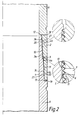
- Figures 1 and 2 show a pipe connector comprising a tubular pin member 1 and a tubular box member 2, which may be formed separately for connection, e.g. by welding or bolting to the ends of two pipe sections to be connected thereby.
- the members are formed or cut directly on the ends of the pipe sections A, B.
- the members are designed to be telescoped together with the outer peripheral surface 3 of the pin member 1 and the inner peripheral surface 4 of the box member 2 overlying each other, the surfaces 3, 4 being generally frusto-conical and provided with annular projections 5 and grooves 6 in a central portion 3a, 4a of each surface.
- the annular projections 5 and grooves 6 are axially spaced apart along the surfaces 3, 4 and are relatively dimensioned so that, when the members are fully engaged together, corresponding ones of the projections inter-engage in the grooves to axially lock the members together.
- the pin member 1 has projections 5 and the box member 2 has grooves 6 but it will be understood that these descriptions can be reversed with the pin member having grooves and box member having projections.
- the projections and grooves may be shaped, dimensioned and arranged as described in GB1573945, GB2033518, GB2099529, GB2113335 and GB2138089, and, as described in these specifications, the crest surfaces 7 of the projections, the surfaces between the projections, the root surfaces of the grooves and the surfaces 8 between the grooves, may all lie on conical surfaces which have substantially the same conicity so that, when the members are fully engaged together, the radial extent of the overlap between the engaged projections and grooves is the same for all the projections and grooves.
- the extent of axial overlap between the projections and grooves may be reduced in the regions of the ends of the central portions 3a, 4a of the surfaces 3, 4 to facilitate disengagement.
- a projection may yet have to pass over a plurality, for example three or four, grooves before it reaches its corresponding groove in which it is to engage.
- corresponding pairs of the projections and grooves may be provided with differing axial extents and spacings along the length of the surfaces 3a, 4a.
- the projections 5 and grooves 6 are then arranged, for example as described in GB 2113335, so that at intermediate positions during telescoping of the members 1, 2, after the members have been brought into initial contact, at least some of the crest surfaces 7 of projections 5 spaced along the central portion of the surface 3 and intermediate the ends of the central portion, are aligned with surfaces 8 between the grooves 6, to prevent premature inter-engagement of the projections and grooves.
- annular projections and grooves to prevent intermediate inter-engagement of them can be obtained in any number of different ways, for example as described in GB2113335.
- the members After the members have been telescoped together to their initial positions, they may be fully engaged by simply applying an axial force to the members. Engagement may however be assisted by the application of pressurised hydraulic fluid to the overlapped portions of the surfaces 3, 4.
- the members may be disengaged in the same way, the pressurised fluid expanding the box and/or contracting the pin to permit engagement and disengagement, and lubricating the crest surfaces 7 of the projections 5 and surfaces 8 between the grooves 6 to facilitate sliding of these surfaces over one another.
- the box member 2 is provided with a radial duct 9 for connection to a source of pressurised hydraulic fluid.
- the duct 9 opens inwardly of the box member into the region of the central portion 4a of the surface 4 of the box which is provided with the grooves.
- axially extending grooves 10, 11 are provided, one in the pin member 1 and the other in the box member 2, the duct 9 opening into the groove 11 in the box member.
- sealing means may be provided at or adjacent the ends of the surfaces 3, 4 and the sealing means may be provided in conjunction with means radially restraining the free ends of the members.
- the sealing and radially restraining means comprise an annular axially extending nib or projection 12, 13 provided at the free end of each member and which is received in a corresponding groove 14, 15 at the inner end of the surface of the other member.
- Each nib 12, 13 seals laterally against surface portions 16a, 16b and 17a, 17b of its groove in the other member, the contacting surfaces being appropriately shaped for this purpose.
- each nib 12, 13 is in full interference fit in its corresponding groove when the members are fully engaged together.
- Surface portions 16a and 17a which, as shown, are generally cylindrical, are extended along the surfaces of the members so that the nibs 12, 13 make sealing contact with these surfaces before the members are fully engaged.
- the nibs 12, 13 are, as shown, provided with radially extending collars 12a, 13a which engage the surfaces 16a, 17a, as described in GB2138089. Indeed, sealing between the nibs and grooves may be achieved in a variety of different ways as described in GB2 13 8089.
- ducts 18, 19 are provided connecting the bottoms of the grooves 14, 15 with the exterior of the members.
- the generally frusto-conical surfaces 3, 4 of the members also include end portions 3b, 4b and 3c, 4c between the ends of the central portions 3a, 4a and the nibs 12, 13 and corresponding grooves 14, 15.
- the lengths ofthese surface portions are dependent on the radial extent of engagement between the projections and grooves and the pressure of the hydraulic fluid used to disengage the member.
- the surfaces ofthe end surface portions 3b, 4b and 3c, 4c are radially spaced apart even when the members are fully engaged together
- the end surface portions lie generally on cones but with different cone angles and which are smaller than the angles of the cones enveloping the crest surfaces of the projections and surfaces between the grooves, and so that the end surface portions progressively approach and come into contact in the region of the nibs 12, 13 and grooves 14, 15.
- the number of pairs of ribs 20, 21 provided in each end portion of the connector depends on the length of the end surface portions 3b, 4b and 3c, 4c and the hoop stresses to be sustained. Where a single pair of ribs 20, 21 is provided it will generally be arranged centrally between the ends of the end portion concerned.
- a connector is only to be subject to high internal pressures, then it may be sufficient to provide these ribs only in the end portion adjacent the free end of the pin member and the corresponding end portion of the box member, where the wall of the pin member is of smallest thickness. Where the connector is only to be subject to high external pressures, it may be sufficient to provide these ribs only in the end portion adjacent the free end of the box member and the corresponding end portion of the pin member, where the thickness of the wall of the box member is smallest.
- the amount of material which has to be cut off to form the new free end of the member can be significantly reduced by appropriate dimensioning and positioning of the rib 20 or one of the ribs 20 provided on the free end of each of the members relative to the collars 12a, 13a.
- the rib 20 on the pin member (or that closest to the free end of the pin member) is radially dimensioned so that it will provide the material for the collar 12a which is formed on the nib 12 of the pin member.
- the only part of the material D that is lost in re-cutting the pin member is the length C between the original nib 12 at the free end of the member to the original rib 20.
- the length C depends on the maximum radial extent of the grooves and projections and the cone angle of the surfaces of the projections and grooves. It is independent of the length of the end portions 3b, 4b and 3c, 4c. Accordingly, where the rib 20 (or one of the ribs 20) is positioned to form the collar 1 2a when the member is re-cut and is spaced from the centre of the end portions 3b, 4b or 3c, 4c, at least another pair of ribs 20, 21 may be provided.
- Figure 4 has been described above as showing the pin member, it could equally be considered to show the box member and what happens in re-cutting the box member.
- the members ofthe above described pipe connector may, for example, be made of high tensile steel.
- the invention is applicable to pipe connectors having a variety of diameters and wall thicknesses and, by way of example only, the outside diameter of the pipe section may vary between 36"/91.44 cm (and larger) and 8 5 ⁇ 8"/21.91 cm (and smaller).
Landscapes
- Engineering & Computer Science (AREA)
- General Engineering & Computer Science (AREA)
- Mechanical Engineering (AREA)
- Mining & Mineral Resources (AREA)
- Life Sciences & Earth Sciences (AREA)
- Geology (AREA)
- Environmental & Geological Engineering (AREA)
- Fluid Mechanics (AREA)
- Physics & Mathematics (AREA)
- General Life Sciences & Earth Sciences (AREA)
- Geochemistry & Mineralogy (AREA)
- Quick-Acting Or Multi-Walled Pipe Joints (AREA)
- Supports For Pipes And Cables (AREA)
- Joints Allowing Movement (AREA)
- Paper (AREA)
- Mutual Connection Of Rods And Tubes (AREA)
Abstract
Description
Claims (9)
- A connector for connecting pipe sections (A,B) comprising a tubular pin member (1) having a generally frusto-conical outer peripheral surface (3) and a tubular box member (2) having a generally frusto-conical inner peripheral surface (4) corresponding to the frusto-conical outer peripheral surface (3) of the pin member (1) and which overlies the outer peripheral surface (4) of the pin member when the members are fully engaged together, each frusto-conical surface (3,4) comprising a central portion (3a,4a) and end portions (3b,4b,3c,4c) between the central portion (3a4a) and the end of the surfaces (3,4), the central portions of the surfaces being provided with a plurality of annular projections (5) and grooves (6) which are inter-engaged when the members (1,2) are fully engaged together to axially lock the members together, means (12,13,14,15) being provided for sealing the free end of one member to the other member when the members are fully engaged together, wherein the end surface portions (3b,4b,3c,4c) of the members (1,2) adjacent the free end of the one member are radially spaced apart and a radially extending annular rib (20,21) is provided intermediate the ends of each end portion, the ribs being axially aligned and radially dimensioned so that, when the members (1,2) are fully engaged together, the crest surfaces of the ribs are in contact or substantially in contact so that in use where there is a substantial pressure difference across the walls of the connector, the ribs (20,21) serve to transfer hoop stresses in the region of the one end surface portion of one member of the connector to the other.
- A connector according to claim 1 wherein the one member is the pin member (1).
- A connector according to claim 1 wherein the one member is the box member (2).
- A connector according to any one of claims 1 to 3 wherein the crest surfaces of the ribs (20,21) are frusto-conical.
- A connector according to claim 4, wherein the crest surfaces of the ribs (20,21) have substantially the same conicity as the crest surfaces of the projections and the surfaces between the grooves.
- A pipe connector according to any one of the preceding claims, wherein the members (1,2) are integral with the pipe sections (A,B).
- A pipe connector according to any one of the preceding claims, wherein the ribs (20,21) are arranged substantially centrally of the end portions (3b,4b,3c,4c).
- A connector according to any one of claims 1 to 7, wherein two or more pairs of ribs (20,21) are provided between the ends of the end portions.
- A connector according to any one of the preceding claims, wherein said means (12,13,14,15) for sealing comprises an annular collar (12,13) to form a seal at the end of the connector with a complementary recess (14,15), and the or each annular rib projects radially beyond the collar (12,13) and is otherwise dimension so that, following wear of the connector, the or each member (1,2) may be re-cut by cutting back the original connector to the rib (20,21), the rib then providing the material for the annular collar.
Applications Claiming Priority (2)
| Application Number | Priority Date | Filing Date | Title |
|---|---|---|---|
| GBGB9706084.2A GB9706084D0 (en) | 1997-03-24 | 1997-03-24 | Improvements in and relating to pipe connectors |
| GB9706084 | 1997-03-24 |
Publications (3)
| Publication Number | Publication Date |
|---|---|
| EP0867597A2 true EP0867597A2 (en) | 1998-09-30 |
| EP0867597A3 EP0867597A3 (en) | 1998-12-02 |
| EP0867597B1 EP0867597B1 (en) | 2001-11-21 |
Family
ID=10809777
Family Applications (1)
| Application Number | Title | Priority Date | Filing Date |
|---|---|---|---|
| EP98302007A Expired - Lifetime EP0867597B1 (en) | 1997-03-24 | 1998-03-16 | Pipe connector |
Country Status (6)
| Country | Link |
|---|---|
| US (1) | US5964486A (en) |
| EP (1) | EP0867597B1 (en) |
| BR (1) | BR9806514A (en) |
| DE (1) | DE69802584T2 (en) |
| GB (1) | GB9706084D0 (en) |
| NO (1) | NO328674B1 (en) |
Cited By (3)
| Publication number | Priority date | Publication date | Assignee | Title |
|---|---|---|---|---|
| WO2011128658A1 (en) * | 2010-04-15 | 2011-10-20 | Oil States Industries (U.K.) Limited | Pipe connector device |
| EP2852784A4 (en) * | 2012-05-22 | 2016-04-06 | Single Buoy Moorings | Pipe connection |
| GB2540038A (en) * | 2015-06-02 | 2017-01-04 | Dril-Quip Inc | Anti-rotation device for connector assembly |
Families Citing this family (43)
| Publication number | Priority date | Publication date | Assignee | Title |
|---|---|---|---|---|
| US6485063B1 (en) * | 1996-05-15 | 2002-11-26 | Huey P. Olivier | Connection |
| UA66876C2 (en) * | 1998-09-07 | 2004-06-15 | Валлурек Маннесманн Ойл Енд Гес Франс | Threaded joint of two metal pipes with a slot made in the threading |
| FR2811056B1 (en) * | 2000-06-30 | 2003-05-16 | Vallourec Mannesmann Oil & Gas | TUBULAR THREADED JOINT SUITABLE FOR DIAMETRIC EXPANSION |
| OA12469A (en) * | 2001-05-24 | 2006-06-01 | Shell Int Research | Radially expandable tubular with supported end portion. |
| FR2844331B1 (en) * | 2002-01-03 | 2004-11-26 | Vallourec Mannesmann Oil & Gas | PROCESS FOR PRODUCING A SEALED TUBULAR JOINT WITH PLASTIC EXPANSION |
| FR2834325B1 (en) * | 2002-01-03 | 2004-03-26 | Vallourec Mannesmann Oil & Gas | TUBULAR THREADED JOINT HAVING SEALING SURFACES |
| CN100387804C (en) * | 2003-05-05 | 2008-05-14 | 国际壳牌研究有限公司 | Expansion device for expanding a pipe |
| FR2868146B1 (en) * | 2004-03-26 | 2009-01-23 | Vallourec Mannesmann Oil Gas F | TUBULAR THREAD RESISTANT TO FLEXION CONSTRAINTS |
| US8220842B2 (en) * | 2003-05-30 | 2012-07-17 | Vallourec Mannesmann Oil & Gas France | Threaded tubular connection which is resistant to bending stresses |
| FR2863033B1 (en) * | 2003-11-28 | 2007-05-11 | Vallourec Mannesmann Oil & Gas | REALIZATION, BY PLASTIC EXPANSION, OF A SEALED TUBULAR JOINT WITH INCLINED STRAINING SURFACE (S) |
| FR2863029B1 (en) * | 2003-11-28 | 2006-07-07 | Vallourec Mannesmann Oil & Gas | REALIZATION, BY PLASTIC EXPANSION, OF A SEALED TUBULAR JOINT WITH INITIAL LOCAL SENSITIZER (S) (S) |
| RU2358088C2 (en) * | 2004-01-27 | 2009-06-10 | Бейкер Хьюз Инкорпорейтед | Slip bushing with turn fixation for performing drilling operations and completion of well via pipe string |
| US20050284659A1 (en) * | 2004-06-28 | 2005-12-29 | Hall David R | Closed-loop drilling system using a high-speed communications network |
| US7093654B2 (en) * | 2004-07-22 | 2006-08-22 | Intelliserv, Inc. | Downhole component with a pressure equalization passageway |
| CA2481609A1 (en) * | 2004-09-28 | 2006-03-28 | Argus Machine Co. Ltd. | Threaded connection for drill pipes |
| US7798536B2 (en) * | 2005-08-11 | 2010-09-21 | Weatherford/Lamb, Inc. | Reverse sliding seal for expandable tubular connections |
| US20070035131A1 (en) * | 2005-08-11 | 2007-02-15 | Grinaldi Ltd | Expandable tubular connection |
| US7699354B2 (en) * | 2006-04-28 | 2010-04-20 | Beard Michael E | Marine riser assembly |
| FR2912730B1 (en) * | 2007-02-21 | 2012-07-06 | Vallourec Mannesmann Oil & Gas France | DEVICE FOR PROTECTING A FEMALE END OF A TUBULAR JOINT COMPONENT WITH ANTI-CUT-OFF BRAKE. |
| US20080238094A1 (en) * | 2007-03-28 | 2008-10-02 | Grant Prideco, L.P. | Oilfield Threaded Connection |
| US7823639B2 (en) * | 2007-09-27 | 2010-11-02 | Intelliserv, Llc | Structure for wired drill pipe having improved resistance to failure of communication device slot |
| GB2461134A (en) * | 2008-06-27 | 2009-12-30 | Oil States Ind | Pipe connector |
| CN101333913B (en) * | 2008-07-30 | 2011-06-29 | 深圳市远东石油钻采工程有限公司 | Oil gas field water separation pipe joint |
| US20110227338A1 (en) * | 2010-03-22 | 2011-09-22 | Jack Pollack | Sealed pipe joint |
| US9828812B2 (en) | 2010-03-22 | 2017-11-28 | Single Buoy Moorings, Inc. | Sealed pipe joint |
| DE202011050823U1 (en) * | 2011-07-27 | 2012-10-29 | Rehau Ag + Co. | line element |
| JP5783146B2 (en) * | 2012-08-08 | 2015-09-24 | 新日鐵住金株式会社 | Threaded joints for steel pipes |
| US8894101B2 (en) * | 2012-09-07 | 2014-11-25 | Vetco Gray Inc. | Protected integral metal to metal seal |
| US9400069B2 (en) * | 2013-01-02 | 2016-07-26 | Frank's International, Llc | Threaded connector for larger diameter tubular members |
| US10428594B2 (en) * | 2013-11-22 | 2019-10-01 | Vetco Gray, LLC | Alignment guide feature for metal to metal seal protection on mechanical connections and couplings |
| CN106461126B (en) * | 2014-06-20 | 2018-12-21 | 新日铁住金株式会社 | Screw joint for steel pipe |
| US10301889B2 (en) * | 2014-09-12 | 2019-05-28 | Single Buoy Moorings, Inc. | Dynamic riser mechanical connector |
| US11156313B2 (en) | 2015-04-16 | 2021-10-26 | Krzysztof Jan Wajnikonis | Mechanical connectors |
| GB2591879B (en) | 2015-04-16 | 2021-12-15 | Jan Wajnikonis Krzysztof | Mechanical connector utilizing keys |
| US11781682B2 (en) * | 2015-04-16 | 2023-10-10 | Krzysztof Jan Wajnikonis | Enhancements of mechanical connector technology |
| US11906079B2 (en) | 2015-04-16 | 2024-02-20 | Krzysztof Jan Wajnikonis | Telescopically assembled mechanical connector |
| US10598305B2 (en) | 2015-08-19 | 2020-03-24 | Lord Corporation | Flexible pipe joint |
| EA037807B1 (en) * | 2017-05-22 | 2021-05-24 | Ниппон Стил Корпорейшн | Threaded connection for steel pipes |
| CN107345608A (en) * | 2017-07-31 | 2017-11-14 | 天津大学 | A kind of underwater Management of Pipeline Mechanical Equipment connector |
| EP3660378B1 (en) * | 2017-11-09 | 2022-12-28 | Nippon Steel Corporation | Threaded connection for steel pipe |
| DE102018109859A1 (en) * | 2018-04-24 | 2019-10-24 | Egeplast International Gmbh | Connecting element for the connection of pipelines |
| US20200190915A1 (en) | 2018-12-18 | 2020-06-18 | Baker Hughes, A Ge Company, Llc | Guiding sleeve for aligning downhole tubulars |
| EP3819507B1 (en) | 2019-11-06 | 2023-01-04 | Crompton Technology Group Limited | Composite shaft with end fitting |
Citations (4)
| Publication number | Priority date | Publication date | Assignee | Title |
|---|---|---|---|---|
| FR1300262A (en) * | 1961-06-20 | 1962-08-03 | Tech Et Commerciale Des Canali | Device for the watertight connection of the elements of a fluid transport pipe |
| DE3207180C1 (en) * | 1982-02-27 | 1983-07-28 | Mannesmann AG, 4000 Düsseldorf | Pipe connection for metal pipes |
| US4707001A (en) * | 1986-06-20 | 1987-11-17 | Seal-Tech, Inc. | Liner connection |
| EP0386372A2 (en) * | 1989-03-08 | 1990-09-12 | Baroid Technology, Inc. | Threaded pipe joint having improved seal ring entrapment |
Family Cites Families (7)
| Publication number | Priority date | Publication date | Assignee | Title |
|---|---|---|---|---|
| GB2033518B (en) * | 1978-11-10 | 1983-01-26 | Hunting Oilfield Services Ltd | Pipe connectors |
| US4298221A (en) * | 1977-01-26 | 1981-11-03 | Hunting Oilfield Services (U.K.) Limited | Pipe connectors |
| GB2099529B (en) * | 1981-06-02 | 1984-07-04 | Hunting Oilfield Services Ltd | Improvements in and relating to pipe connectors |
| GB2113335B (en) * | 1982-01-18 | 1985-01-16 | Hunting Oilfield Services | Improvements in and relating to pipe connectors |
| GB2113334B (en) * | 1982-01-18 | 1985-11-13 | Hunting Oilfield Services | Improvements in and relating to pipe connectors |
| GB2138089B (en) * | 1983-04-05 | 1986-09-17 | Hunting Oilfield Services | Pipe connectors |
| US5709417A (en) * | 1994-07-20 | 1998-01-20 | Verbeck; Ronald J. | Interference pipe coupling |
-
1997
- 1997-03-24 GB GBGB9706084.2A patent/GB9706084D0/en active Pending
-
1998
- 1998-03-16 EP EP98302007A patent/EP0867597B1/en not_active Expired - Lifetime
- 1998-03-16 DE DE69802584T patent/DE69802584T2/en not_active Expired - Lifetime
- 1998-03-23 NO NO19981306A patent/NO328674B1/en not_active IP Right Cessation
- 1998-03-23 BR BR9806514-9A patent/BR9806514A/en not_active IP Right Cessation
- 1998-03-23 US US09/045,861 patent/US5964486A/en not_active Expired - Lifetime
Patent Citations (4)
| Publication number | Priority date | Publication date | Assignee | Title |
|---|---|---|---|---|
| FR1300262A (en) * | 1961-06-20 | 1962-08-03 | Tech Et Commerciale Des Canali | Device for the watertight connection of the elements of a fluid transport pipe |
| DE3207180C1 (en) * | 1982-02-27 | 1983-07-28 | Mannesmann AG, 4000 Düsseldorf | Pipe connection for metal pipes |
| US4707001A (en) * | 1986-06-20 | 1987-11-17 | Seal-Tech, Inc. | Liner connection |
| EP0386372A2 (en) * | 1989-03-08 | 1990-09-12 | Baroid Technology, Inc. | Threaded pipe joint having improved seal ring entrapment |
Cited By (7)
| Publication number | Priority date | Publication date | Assignee | Title |
|---|---|---|---|---|
| WO2011128658A1 (en) * | 2010-04-15 | 2011-10-20 | Oil States Industries (U.K.) Limited | Pipe connector device |
| GB2491529A (en) * | 2010-04-15 | 2012-12-05 | Oil States Ind Uk Ltd | Pipe connector device |
| EP2852784A4 (en) * | 2012-05-22 | 2016-04-06 | Single Buoy Moorings | Pipe connection |
| GB2540038A (en) * | 2015-06-02 | 2017-01-04 | Dril-Quip Inc | Anti-rotation device for connector assembly |
| US10385994B2 (en) | 2015-06-02 | 2019-08-20 | Dril-Quip, Inc. | Anti-rotation device for connector assembly |
| GB2540038B (en) * | 2015-06-02 | 2021-07-14 | Dril Quip Inc | Anti-rotation device for connector assembly |
| US11454338B2 (en) | 2015-06-02 | 2022-09-27 | Dril-Quip, Inc. | Anti-rotation device for connector assembly |
Also Published As
| Publication number | Publication date |
|---|---|
| NO328674B1 (en) | 2010-04-26 |
| EP0867597A3 (en) | 1998-12-02 |
| DE69802584D1 (en) | 2002-01-03 |
| EP0867597B1 (en) | 2001-11-21 |
| NO981306D0 (en) | 1998-03-23 |
| BR9806514A (en) | 2001-03-20 |
| GB9706084D0 (en) | 1997-05-14 |
| DE69802584T2 (en) | 2002-07-25 |
| NO981306L (en) | 1998-09-25 |
| US5964486A (en) | 1999-10-12 |
Similar Documents
| Publication | Publication Date | Title |
|---|---|---|
| US5964486A (en) | Pipe connectors | |
| EP0803637B1 (en) | Pipe connector device with pin and box members having corresponding frusto-conical surfaces | |
| US4525001A (en) | Pipe connector with interengagable tubular pin and tubular box members | |
| AU2009263947B2 (en) | Pipe connector device | |
| US4629221A (en) | Pipe connectors | |
| CA1288453C (en) | Pipe connectors | |
| GB2099529A (en) | Improvements in and relating to pipe connectors | |
| US4298221A (en) | Pipe connectors | |
| EP0757768B1 (en) | Device for permanent joining of tubes | |
| EP0663555B1 (en) | Tube union assembly | |
| EP1106778A1 (en) | Seal for expandable tubular connections | |
| GB2033518A (en) | Improvements in and relating to pipe connectors | |
| US6439617B1 (en) | Coupler for a pipe or hose section | |
| US20130033035A1 (en) | Pipe Connector Device | |
| NO336472B1 (en) | Threaded connection for pipes, with seal against external pressure | |
| US5709417A (en) | Interference pipe coupling | |
| US4561683A (en) | Pipe connector with interengageable tubular pin and tubular box members | |
| GB2138089A (en) | Pipe connectors | |
| GB1573945A (en) | Pipe connectors | |
| US6234910B1 (en) | Shaft coupling arrangement | |
| US20220341518A1 (en) | Threaded connection including and intermediate shoulder | |
| CN113272515A (en) | Protection device for male buckle end of steel pipe used in tubular oil-gas operation pipe column | |
| GB2159904A (en) | Pipe connectors | |
| AU2013201211A1 (en) | Pipe Connector Device |
Legal Events
| Date | Code | Title | Description |
|---|---|---|---|
| PUAI | Public reference made under article 153(3) epc to a published international application that has entered the european phase |
Free format text: ORIGINAL CODE: 0009012 |
|
| AK | Designated contracting states |
Kind code of ref document: A2 Designated state(s): DE GB |
|
| AX | Request for extension of the european patent |
Free format text: AL;LT;LV;MK;RO;SI |
|
| PUAL | Search report despatched |
Free format text: ORIGINAL CODE: 0009013 |
|
| AK | Designated contracting states |
Kind code of ref document: A3 Designated state(s): AT BE CH DE DK ES FI FR GB GR IE IT LI LU MC NL PT SE |
|
| AX | Request for extension of the european patent |
Free format text: AL;LT;LV;MK;RO;SI |
|
| 17P | Request for examination filed |
Effective date: 19990601 |
|
| AKX | Designation fees paid |
Free format text: DE GB |
|
| 17Q | First examination report despatched |
Effective date: 19991222 |
|
| GRAG | Despatch of communication of intention to grant |
Free format text: ORIGINAL CODE: EPIDOS AGRA |
|
| GRAG | Despatch of communication of intention to grant |
Free format text: ORIGINAL CODE: EPIDOS AGRA |
|
| GRAH | Despatch of communication of intention to grant a patent |
Free format text: ORIGINAL CODE: EPIDOS IGRA |
|
| GRAH | Despatch of communication of intention to grant a patent |
Free format text: ORIGINAL CODE: EPIDOS IGRA |
|
| GRAA | (expected) grant |
Free format text: ORIGINAL CODE: 0009210 |
|
| AK | Designated contracting states |
Kind code of ref document: B1 Designated state(s): DE GB |
|
| REG | Reference to a national code |
Ref country code: GB Ref legal event code: IF02 |
|
| REF | Corresponds to: |
Ref document number: 69802584 Country of ref document: DE Date of ref document: 20020103 |
|
| PLBE | No opposition filed within time limit |
Free format text: ORIGINAL CODE: 0009261 |
|
| STAA | Information on the status of an ep patent application or granted ep patent |
Free format text: STATUS: NO OPPOSITION FILED WITHIN TIME LIMIT |
|
| 26N | No opposition filed | ||
| PGFP | Annual fee paid to national office [announced via postgrant information from national office to epo] |
Ref country code: DE Payment date: 20170222 Year of fee payment: 20 |
|
| PGFP | Annual fee paid to national office [announced via postgrant information from national office to epo] |
Ref country code: GB Payment date: 20170224 Year of fee payment: 20 |
|
| REG | Reference to a national code |
Ref country code: DE Ref legal event code: R071 Ref document number: 69802584 Country of ref document: DE |
|
| REG | Reference to a national code |
Ref country code: GB Ref legal event code: PE20 Expiry date: 20180315 |
|
| PG25 | Lapsed in a contracting state [announced via postgrant information from national office to epo] |
Ref country code: GB Free format text: LAPSE BECAUSE OF EXPIRATION OF PROTECTION Effective date: 20180315 |