EP0866636A2 - Voice coil and method for production thereof - Google Patents
Voice coil and method for production thereof Download PDFInfo
- Publication number
- EP0866636A2 EP0866636A2 EP98104667A EP98104667A EP0866636A2 EP 0866636 A2 EP0866636 A2 EP 0866636A2 EP 98104667 A EP98104667 A EP 98104667A EP 98104667 A EP98104667 A EP 98104667A EP 0866636 A2 EP0866636 A2 EP 0866636A2
- Authority
- EP
- European Patent Office
- Prior art keywords
- voice coil
- membrane
- former
- centering
- strands
- Prior art date
- Legal status (The legal status is an assumption and is not a legal conclusion. Google has not performed a legal analysis and makes no representation as to the accuracy of the status listed.)
- Ceased
Links
Images


Classifications
-
- H—ELECTRICITY
- H04—ELECTRIC COMMUNICATION TECHNIQUE
- H04R—LOUDSPEAKERS, MICROPHONES, GRAMOPHONE PICK-UPS OR LIKE ACOUSTIC ELECTROMECHANICAL TRANSDUCERS; DEAF-AID SETS; PUBLIC ADDRESS SYSTEMS
- H04R9/00—Transducers of moving-coil, moving-strip, or moving-wire type
- H04R9/02—Details
- H04R9/04—Construction, mounting, or centering of coil
- H04R9/046—Construction
Definitions
- the invention is concerned with the formation and manufacture of voice coil arrangements, with a particular emphasis on reducing the weight of such arrangements.
- Voice coil arrangements in the sense of this application essentially comprise one Voice coil former with voice coil, a centering membrane and strands.
- The is in As a rule, tubular voice coil carriers are connected to the voice coil.
- the centering diaphragm is arranged at an axial distance from the voice coil and also with connected to the voice coil former by means of an adhesive seam.
- the centering membrane which extends radially to the longitudinal extent of the voice coil bobbin, depending on the training either an accordion or wavy contour.
- the two voice coil wires of the voice coil are each conductive via a soldering point with one of the two strands connected.
- Loudspeaker manufacturing For the formation of voice coil arrangements, which are often used as a prefabricated part Loudspeaker manufacturing have been used in the prior art developed two main manufacturing processes.
- the voice coil is first placed on the carrier wrapped and baked and then the inside diameter of the neck of the membrane connected to the outer diameter of the voice coil former. Unless the voice coil wires before connecting the membrane to the voice coil former were soldered to the strands, they are now connected to the strands via the soldering points. Then, after applying a bead of adhesive to the neck of the membrane, the Centering membrane pushed over the voice coil and with the outer diameter of the Neck of the membrane glued. If the soldering points are not already before the opening of the Centering membrane were glued to the bottom, they are now to the bottom of the Membrane glued.
- the voice coil with the Voice coil former and the voice coil wires over the soldering points with the strands connected the voice coil with the Voice coil former and the voice coil wires over the soldering points with the strands connected.
- this procedure has the disadvantage that relatively much adhesive for attaching the centering membrane to the voice coil former necessary is. This is due to the fact that the centering membrane in the second Procedure must have a relatively large inner diameter in order to Sliding the centering membrane over the voice coil will damage the Exclude voice coil.
- the object of the invention based on a weight-reduced voice coil arrangement and an automatable To tackle processes for their manufacture.
- the inner diameter of the neck is greater than / equal to the outer diameter of the voice coil former plus at least twice the material thickness of the Centering membrane and is the first area of the contour of the centering membrane at least is partially located between the voice coil former and the neck of the membrane created a very compact voice coil arrangement with a minimal overall height.
- the neck of the membrane with the Inner diameter of the voice coil bobbin is connected (claim 4), in which all Height rendering requirements are satisfied.
- a particularly compact arrangement is given according to claim 5 when the adhesive seam between the first area of the centering membrane and the voice coil former and the Neck of the membrane have substantially the same axial distance from the voice coil.
- a complete automatability of a method for producing a voice coil arrangement according to one of claims 1-5 is given according to claim 6 if - After the voice coil with the voice coil former and the voice coil wires are connected to the strands via the soldering points - the strands above the end of the Voice coil former, which will later be connected to the membrane, fixed and be pulled tight so that the voice coil wires, if they are not already with the Voice coil carriers are connected via the baked enamel connection, the solder points and the strands lie close to the voice coil former.
- the centering membrane the inner edge of which is equal to the outer diameter of the voice coil former, can be easily pushed to the area where the solder points on the voice coil former issue.
- the strands attached to the voice coil support hinder the specified diameter ratios of the inner edge of the centering membrane Do not push it onto the voice coil former because the centering membrane respective contour in the radial direction elastically evades the somewhat bulky strands.
- the centering membrane has reached its end position on the voice coil former, lie the solder points between the first area of the respective contour of the centering membrane and the voice coil former, so that for the establishment of a permanent connection of Centering membrane, solder points and voice coil former only one adhesive seam in the Gap between the voice coil bobbin and the first area must be formed.
- the Adhesive seam between centering membrane and voice coil former also for fastening the Soldering points can be used.
- the end of the voice coil former which later with the Membrane should be connected, at least during step four towards Earth's center, gravity can evenly distribute the adhesive in the Space between the voice coil former and the first area of the centering membrane be exploited.
- Is the voice coil former according to claim 9 at least during the execution of the Steps two to four arranged on at least one working mandrel are damage excluded the voice coil arrangement during the automatic manufacturing process, because the spine or mandrels do not allow manual handling of the spool necessary is.
- a particularly advantageous procedure is given according to claim 10 if - before the glued seam has hardened - which - until then still fixed and pulled tight - Strands essentially arcuate over the surface of the voice coil facing away from the voice coil Centering membrane are guided. This arcuate guidance of the strands causes Strands with regard to their later course after the adhesive seam has hardened in the area the connection of voice coil former, solder points and centering membrane is a preferred direction receive.
- a centering membrane 10 is shown in a sectional view. This is clear The illustration shows that the centering membrane 10 has an accordion-shaped contour has and centrally has an opening 11. The one immediately surrounding the opening 11 The area of the centering membrane 10 is that which is the first in this application Area 12 is designated. Since here the contour of the centering membrane 10 is accordion-shaped is formed, the first region 12 has an oblique relation to the center line Course.
- a voice coil bobbin 13 is shown, which is tubular.
- This Voice coil former 13 is arranged on a working mandrel 14 which is one of the Voice coil bobbin 13 filled space 15 and at the upper end 16 of the Voice coil former 13 emerges from this.
- the voice coil 18 is attached to the voice coil bobbin 13.
- the two voice coil wires 19, which are connected to the voice coil 18, are on the outer jacket 20 of the voice coil bobbin 13 in the direction of the upper end 16 of the Voice coil carrier 13 guided along and each with a soldering point 21 with the likewise on the outer jacket 20 of the voice coil bobbin 13 along strands 22 conductively connected.
- the contact of the coil wires 19, the soldering points 21 and the strands 22 on the outer jacket 20 of the voice coil bobbin 13 was achieved in that the strands 22nd fixed and tightened in notches 23 arranged at the upper end of the working mandrel 14 were.
- the notches 23 are only mentioned as examples. Rather, the tightening and The strands 22 can also be fixed in another manner known to the person skilled in the art.
- FIG. 2a If the centering membrane 10 shown in FIG. 1a is pushed onto a voice coil bobbin 13 according to FIG. 1b in the direction of arrow P1 at the upper end 16, conditions are established which are shown in FIG. 2a.
- the voice coil bobbin 13 has been rotated 90 ° clockwise compared to FIG. 1b in FIG. 2a. 2a that the inner edge 24 of the centering membrane 10 bears against the outer jacket 20 of the voice coil bobbin 13 and the first region 12 of the centering membrane 10 opens in the direction of the voice coil 18. It can also be seen from the illustration in FIG.
- the soldering point 21 and the braid 22 lie against the outer jacket 20 of the voice coil bobbin 13, since the braid 22 is fixed and pulled tight in the notch 23 shown.
- the visible soldering point 21 lies between the first area 12 of the centering membrane 10 and the outer jacket 20 of the voice coil bobbin 13.
- the gluing between the voice coil bobbin 13, the centering membrane 10 and the guide point 21 was realized in such a way that in the space 25 between the first area 12 and an adhesive seam 26 was formed on the outer jacket 20 of the voice coil bobbin 13.
- the adhesive seam 26 in one other - not shown - embodiment even before postponing the Centering membrane 10 on the voice coil bobbin 13 or fixing and tightening the strands 22 can be formed on the voice coil former 13. In this case, then the centering membrane 10 pushed into the adhesive seam 26.
- the centering membrane 10 has its end position shown in Fig. 2a on the voice coil former 13 and the adhesive seam 26 is formed, the strands 22 should come out of the notches 23 taken or in another - not shown - embodiment with the respective clamping and fixing arrangement in the direction of arrow P2 arcuate over the top 27 of the centering membrane 10 are guided. Then hardens the adhesive seam 26, get the Strands 22 already have a certain preferred direction with regard to their later attachment points on the speaker basket (everything not shown).
- FIG. 2b shows a membrane 28 which has a neck 29. Is the inside diameter greater / equal to the outer diameter of the voice coil bobbin 13 and the membrane 28 lowered on the voice coil bobbin 13 in the direction of the arrow P3, conditions arise a, which are shown schematically in Fig. 3.
- Fig. 5a can be seen that in an arrangement according to FIG. 3, the strand 22 between the Neck 29 of the membrane 28 and the centering membrane 10 emerges and that the neck 29 and the Centering membrane 10 almost without distance in the longitudinal direction of the voice coil bobbin 13 are arranged to each other.
- FIG. 5b in which the adhesive seam (26) is not shown for reasons of clarity and in which, for the same reasons, a small distance between the voice coil bobbin 13, the centering membrane 10, the soldering points 21, and strand 22 and the neck 29 of the Membrane 28 is realized shows that if all the parts just mentioned are present, the Soldering points 21, the strands 22 and the upper edge 24 of the centering membrane 10 between the Voice coil support 13 and the neck 29 of the membrane 28 are arranged.
- the neck 29 of the membrane 28 is on in FIG. 5d attached to the inside 30 of the voice coil bobbin 13.
- the neck 29 and the adhesive seam 26 refer to the longitudinal direction of the voice coil bobbin 13 are arranged substantially in the same plane.
Landscapes
- Physics & Mathematics (AREA)
- Engineering & Computer Science (AREA)
- Acoustics & Sound (AREA)
- Signal Processing (AREA)
- Audible-Bandwidth Dynamoelectric Transducers Other Than Pickups (AREA)
Abstract
Description
Die Erfindung befaßt sich mit Ausbildung und Herstellung von Schwingspulenanordnungen, wobei ein besonderer Schwerpunkt auf der Gewichtsreduzierung solcher Anordnungen liegt.The invention is concerned with the formation and manufacture of voice coil arrangements, with a particular emphasis on reducing the weight of such arrangements.
Schwingspulenanordnungen im Sinne dieser Anmeldung umfassen im wesentlichen einen Schwingspulenträger mit Schwingspule, eine Zentriermembran und Litzen. Dabei ist der in aller Regel rohrförmig ausgebildete Schwingspulenträger mit der Schwingspule verbunden. In axialem Abstand zur Schwingspule ist die Zentriermembran angeordnet und gleichfalls mit dem Schwingspulenträger mittels einer Klebenaht verbunden. Die Zentriermembran, welche sich radial zur Längserstreckung des Schwingspulenträgers erstreckt, hat je nach Ausbildung entweder eine ziehharmonika- oder wellenförmige Kontur. Die beiden Schwingspulendrähte der Schwingspule sind jeweils über einen Lötpunkt mit einem der beiden Litzen leitend verbunden.Voice coil arrangements in the sense of this application essentially comprise one Voice coil former with voice coil, a centering membrane and strands. The is in As a rule, tubular voice coil carriers are connected to the voice coil. The centering diaphragm is arranged at an axial distance from the voice coil and also with connected to the voice coil former by means of an adhesive seam. The centering membrane, which extends radially to the longitudinal extent of the voice coil bobbin, depending on the training either an accordion or wavy contour. The two voice coil wires of the voice coil are each conductive via a soldering point with one of the two strands connected.
Zur Ausbildung von Schwingspulenanordnungen, welche vielfach als vorgefertigtes Teil zur Lautsprecherherstellung verwendet werden, haben sich im Stand der Technik im wesentlichen zwei Herstellungsverfahren herausgebildet.For the formation of voice coil arrangements, which are often used as a prefabricated part Loudspeaker manufacturing have been used in the prior art developed two main manufacturing processes.
Gemäß dem ersten bekannten Verfahren wird zunächst die Schwingspule auf den Träger gewickelt und verbacken sowie anschließend der Innendurchmesser des Halses der Membran mit dem Außendurchmesser des Schwingspulenträgers verbunden. Sofern die Schwingspulendrähte vor dem Verbinden der Membran mit dem Schwingspulenträger noch nicht mit den Litzen verlötet waren, werden sie jetzt über die Lötpunkte mit den Litzen verbunden. Dann wird, nachdem am Hals der Membran eine Kleberaupe aufgetragen wurde, die Zentriermembran über die Schwingspule geschoben und mit dem Außendurchmesser des Halses der Membran verklebt. Wenn die Lötpunkte nicht schon vor dem Aufschieben der Zentriermembran mit der Unterseite verklebt waren, werden sie jetzt mit der Unterseite der Membran verklebt. According to the first known method, the voice coil is first placed on the carrier wrapped and baked and then the inside diameter of the neck of the membrane connected to the outer diameter of the voice coil former. Unless the voice coil wires before connecting the membrane to the voice coil former were soldered to the strands, they are now connected to the strands via the soldering points. Then, after applying a bead of adhesive to the neck of the membrane, the Centering membrane pushed over the voice coil and with the outer diameter of the Neck of the membrane glued. If the soldering points are not already before the opening of the Centering membrane were glued to the bottom, they are now to the bottom of the Membrane glued.
Gemäß dem weiteren bekannten Verfahren werden zunächst die Schwingspule mit dem Schwingspulenträger und die Schwingspulendrähte über die Lötpunkte mit den Litzen verbunden.According to the further known method, the voice coil with the Voice coil former and the voice coil wires over the soldering points with the strands connected.
Anschließend werden die Lötpunkte mit dem Schwingspulenträger verliebt. Sodann wird die Zentriermembran von dem Ende des Schwingspulenträgers, welches nicht mit der Membran verbunden wird, auf den Schwingspulenträger aufgeschoben und mittels einer Klebenaht, welche zwischen den Klebestellen für die Lötpunkte und der Schwingspule liegt, am Schwingspulenträger befestigt.Then the solder points are in love with the voice coil former. Then will the centering membrane from the end of the voice coil bobbin, which is not with the Connected membrane, pushed onto the voice coil former and by means of a Adhesive seam, which lies between the adhesive points for the soldering points and the voice coil, attached to the voice coil former.
Diese Verfahrensführung hat gegenüber der ersten Verfahrensführung den Nachteil, daß relativ viel Klebstoff zur Befestigung der Zentriermembran mit dem Schwingspulenträger notwendig ist. Dies ist darauf zurückzuführen, daß die Zentriermembran bei der zweiten Verfahrensführung einen relativ großen Innendurchmesser aufweisen muß, um beim Aufschieben der Zentriermembran über die Schwingspule eine Beschädigung der Schwingspule auszuschließen.Compared to the first procedure, this procedure has the disadvantage that relatively much adhesive for attaching the centering membrane to the voice coil former necessary is. This is due to the fact that the centering membrane in the second Procedure must have a relatively large inner diameter in order to Sliding the centering membrane over the voice coil will damage the Exclude voice coil.
Ein Aufschieben der Zentriermembran von dem Ende des Schwingspulenträgers, welches später mit der Membran verbunden wird, scheidet bei dieser Verfahrensführung aus. Zwar wäre dann ein geringer Innendurchmesser der Zentriermembran möglich, jedoch würde dieser dazu führen, daß die Zentriermembran zwischen den Lötpunkten und dem Ende des Schwingspulenträgers, welches später mit der Membran verbunden wird, angeordnet werden muß. Ein tieferes Herunterschieben der Zentriermembran mit geringerem Innendurchmesser über die Lötpunkte und deren Fixierung am Schwingspulenträger ist bei einer solchen Verfahrensmodifikation nicht möglich, da der geringere Innendurchmesser die Fixierung der Lötpunkte am Schwingspulenträger zerstören bzw. aufheben würde. Schließlich hat das zweite Verfahren gegenüber dem ersten Verfahren auch noch den Nachteil, daß durch die zusätzliche Fixierung der Lötpunkte am Schwingspulenträger dessen Stoß vollständig klebstoffdicht ausgebildet werden muß, um ein Durchdringen von Klebstoff, welcher für die Fixierung der Lötpunkte notwendig ist, an die Innenseite des Schwingspulenträgers auszuschließen. Diese zusätzliche Abdichtung wirkt gewichtserhöhend.Sliding the centering membrane from the end of the voice coil former, which later connected to the membrane, is ruled out in this procedure. Though a small inner diameter of the centering membrane would then be possible, however this cause the centering membrane between the soldering points and the end of the Voice coil former, which is later connected to the membrane, can be arranged got to. A deeper sliding down of the centering membrane with a smaller inner diameter about the soldering points and their fixing to the voice coil former Process modification not possible because the smaller inside diameter fixes the Would destroy or cancel solder points on the voice coil former. After all, that has second method compared to the first method also has the disadvantage that additional fixation of the soldering points on the voice coil bobbin completely Adhesive-tight must be formed to prevent the penetration of adhesive, which is responsible for the Fixing the soldering points is necessary to exclude on the inside of the voice coil former. This additional seal increases the weight.
Zur Vervollständigung der Schwingspulenanordnung wird dann gemäß dem zweiten Verfahren der Schwingspulenträger noch mit der Membran verbunden, wobei allerdings die Verbindung von Schwingspulenträger und Membran auch erst zu einem Zeitpunkt erfolgen kann, in welchem der Schwingspulenträger und die Zentriermembran bereits in einem Lautsprecherkorb montiert ist.To complete the voice coil arrangement is then according to the second Method of the voice coil former still connected to the membrane, although the The voice coil former and membrane are only connected at one time can, in which the voice coil former and the centering membrane already in one Speaker basket is mounted.
Während das erste Verfahren sehr viel manuelle Tätigkeiten erfordert und somit gegenüber dem weiteren Verfahren relativ arbeitsaufwendig ist, haben Schwingspulenanordnungen gemäß dem weiteren Verfahren den zusätzlichen Nachteil, daß wegen der Notwendigkeit der Fixierung der Lötpunkte am Schwingspulenträger solche Schwingspulenträger gegenüber Schwingspulenträgern, welche in Schwingspulenanordnungen nach dem ersten Verfahren verwendet werden, bei sonst gleichen Bedingungen eine um 4-5 mm größere Bauhöhe aufweisen. Abgesehen davon, daß die größere Bauhöhe des Schwingspulenträgers auch mit einer Gewichtserhöhung verbunden ist, wirkt diese zusätzliche Bauhöhe auch als zusätzliche Feder, wodurch die Krafteinprägung in die Membran negativ beeinflußt wird. Letzteres äußert sich insbesondere in einer verschlechterten Höhenwiedergabe. Unabhängig von den letzten Aspekten weisen Schwingspulenanordnungen, welche nach beiden bekannten Verfahren hergestellt sind, den generellen Nachteil auf, daß zu ihrer Ausbildung insgesamt drei Klebenähte notwendig sind, und zwar für die Verbindung von Membran und Zentriermembran jeweils mit dem Schwingspulenträger sowie zur Festlegung der Lötpunkte an der Membran bzw. dem Schwingspulenträger. Daher liegt der Erfindung die Aufgabe zugrunde eine gewichtsreduzierte Schwingspulenanordnung sowie ein automatisierbares Verfahren zu ihrer Herstellung anzugehen.While the first procedure requires a lot of manual work and therefore opposite the further method is relatively labor intensive, have voice coil arrangements according to the further method, the additional disadvantage that because of the need for Fixing the solder points on the voice coil former compared to such voice coil former Voice coil carriers, which are in voice coil arrangements according to the first method are used, with otherwise identical conditions a 4-5 mm higher overall height exhibit. Apart from the fact that the larger height of the voice coil bobbin also with is associated with an increase in weight, this additional height also acts as an additional Spring, which has a negative impact on the force applied to the membrane. The latter manifests itself in particular in a deteriorated height reproduction. Regardless of the last aspects have voice coil arrangements, which according to both known Processes are made, the general disadvantage is that their training as a whole three adhesive seams are necessary, namely for the connection of membrane and Centering membrane with the voice coil former and to determine the soldering points on the membrane or the voice coil former. Therefore, the object of the invention based on a weight-reduced voice coil arrangement and an automatable To tackle processes for their manufacture.
Diese Aufgabe wird vorrichtungsmäßig mit den Merkmalen von Anspruch 1 gelöst.
Vorteilhafte Aus- und Weiterbildungen der Erfindung sind den Ansprüchen 2-5 entnehmbar.
Ein Verfahren zur Herstellung einer Anordnung gemäß einem der Ansprüche 1-5 ist in
Anspruch 6 angegeben. Ein weiteres Herstellungsverfabren ist Anspruch 7 entnehmbar.
Vorteilhafte Ausgestaltungen für beide Verfahren sind in den Ansprüchen 8-10 angegeben.
Öffnet sich gemäß Anspruch 1 der erste Bereich der jeweiligen Kontur der Zentriermembran
in Richtung zur Schwingspule und ist der jeweilige Lötpunkt in der zwischen dem
Schwingspulenträger und dem besagten Bereich angeordneten Klebenaht angeordnet,
entfallen die sonst üblichen zusätzlichen Fixierungen für die Lötpunkte, wodurch
Klebergewicht gespart wird.This object is achieved in terms of the device with the features of
Ist gemäß Anspruch 3 der Innendurchmesser des Halses größer/gleich dem Außendurchmesser des Schwingspulenträgers plus mindestens zweimal der Materialdicke der Zentriermembran und ist der erste Bereich der Kontur der Zentriermembran zumindest teilweise zwischen dem Schwingspulenträger und dem Hals der Membran angeordnet, ist eine sehr kompakte Schwingspulenanordnung mit minimaler Bauhöhe geschaffen. Gleiches gilt auch für eine Anordnung, bei welcher der Hals der Membran mit dem Innendurchmesser des Schwingspulenträgers verbunden ist (Anspruch 4), bei welcher alle Anforderungen in bezug auf die Höhenwiedergabe befriedigt sind. According to claim 3, the inner diameter of the neck is greater than / equal to the outer diameter of the voice coil former plus at least twice the material thickness of the Centering membrane and is the first area of the contour of the centering membrane at least is partially located between the voice coil former and the neck of the membrane created a very compact voice coil arrangement with a minimal overall height. The same applies to an arrangement in which the neck of the membrane with the Inner diameter of the voice coil bobbin is connected (claim 4), in which all Height rendering requirements are satisfied.
Eine besonders kompakte Anordnung ist gemäß Anspruch 5 gegeben, wenn die Klebenaht zwischen dem ersten Bereich der Zentriermembran und dem Schwingspulenträger und der Hals der Membran im wesentlichen den gleichen axialen Abstand zur Schwingspule haben.A particularly compact arrangement is given according to claim 5 when the adhesive seam between the first area of the centering membrane and the voice coil former and the Neck of the membrane have substantially the same axial distance from the voice coil.
Eine vollständige Automatisierbarkeit eines Verfahrens zur Herstellung einer Schwingspulenanordnung nach einem der Ansprüche 1-5 ist gemäß Anspruch 6 dann gegeben, wenn - nachdem die Schwingspule mit dem Schwingspulenträger und die Schwingspulendrähte über die Lötpunkte mit den Litzen verbunden sind - die Litzen oberhalb des Endes des Schwingspulenträgers, welches später mit der Membran verbunden werden soll, fixiert und strammgezogen werden, so daß die Schwingspulendrähte, sofern sie nicht schon mit dem Schwingspulenträger über die Backlackverbindung verbunden sind, die Lötpunkte und die Litzen eng am Schwingspulenträger anliegen. In diesem Fall kann dann die Zentriermembran, deren innerer Rand gleich dem Außendurchmesser des Schwingspulenträgers ist, problemlos bis zu dem Bereich geschoben werden, wo die Lötpunkte am Schwingspulenträger anliegen. Die am Schwingspulenträger anliegenden Litzen behindern bei dem angegebenen Durchmesserverhältnissen des inneren Randes der Zentriermembran deren Aufschieben auf den Schwingspulenträger nicht, da die Zentriermembran durch ihre jeweilige Kontur in Radialrichtung elastisch den etwas auftragenden Litzen ausweicht.A complete automatability of a method for producing a voice coil arrangement according to one of claims 1-5 is given according to claim 6 if - After the voice coil with the voice coil former and the voice coil wires are connected to the strands via the soldering points - the strands above the end of the Voice coil former, which will later be connected to the membrane, fixed and be pulled tight so that the voice coil wires, if they are not already with the Voice coil carriers are connected via the baked enamel connection, the solder points and the strands lie close to the voice coil former. In this case, the centering membrane, the inner edge of which is equal to the outer diameter of the voice coil former, can be easily pushed to the area where the solder points on the voice coil former issue. The strands attached to the voice coil support hinder the specified diameter ratios of the inner edge of the centering membrane Do not push it onto the voice coil former because the centering membrane respective contour in the radial direction elastically evades the somewhat bulky strands.
Hat die Zentriermembran ihre Endlage auf dem Schwingspulenträger eingenommen, liegen die Lötpunkte zwischen dem erstem Bereich der jeweiligen Kontur der Zentriermembran und dem Schwingspulenträger, so daß zur Herstellung einer dauerhaften Verbindung von Zentriermembran, Lötpunkten und Schwingspulenträger nur noch eine Klebenaht im Zwischenraum zwischen Schwingspulenträger und ersten Bereich ausgebildet werden muß. Mit anderen Worten, dadurch, daß die Lötpunkte im Zwischenraum zwischen dem Schwingspulenträger und dem ersten Bereich der Zentriermembran angeordnet sind und die Litzen während des Aufbaus durch die Zugwirkung eng am Schwingspulenträger anliegen, kann die Klebenaht zwischen Zentriermembran und Schwingspulenträger auch zur Befestigung der Lötpunkte genutzt werden.If the centering membrane has reached its end position on the voice coil former, lie the solder points between the first area of the respective contour of the centering membrane and the voice coil former, so that for the establishment of a permanent connection of Centering membrane, solder points and voice coil former only one adhesive seam in the Gap between the voice coil bobbin and the first area must be formed. In other words, in that the solder points in the space between the voice coil former and the first region of the centering membrane are arranged and the strands during the construction due to the tensile effect close to the voice coil former, the Adhesive seam between centering membrane and voice coil former also for fastening the Soldering points can be used.
Die gleiche vorteilhafte Verfahrensführung ist auch bei der Merkmalskombination gemäß
Anspruch 7 gegeben, bei welcher lediglich vor dem Aufschieben der Zentriermembran eine
Klebenaht am Schwingspulenträger ausgebildet wird und welche zur späteren Befestigung
der Zentriermembran und der Lötpunkte am Schwingspulenträger dient.
Sehr vorteilhaft ist es in diesem Zusammenhang, wenn die Klebenaht schon vor dem Fixieren
und Strammziehen der Litzen ausgebildet wird, weil in diesem Fall eine besonders gute
Befestigung der Lötpunkte am Schwingspulenträger erreicht werden kann.The same advantageous procedure is also given in the combination of features according to claim 7, in which an adhesive seam is formed on the voice coil former only before the centering membrane is pushed on, and which is used for later attachment of the centering membrane and the soldering points on the voice coil former.
In this context, it is very advantageous if the adhesive seam is formed before the strands are fixed and pulled tight, because in this case the soldering points can be attached particularly well to the voice coil former.
Weist gemäß Anspruch 8 das Ende des Schwingspulenträgers, welches später mit der Membran verbunden werden soll, zumindest während Schritt vier in Richtung zum Erdmittelpunkt, kann die Schwerkraft gleichmäßig zur Verteilung des Klebstoffs im Zwischenraum zwischen Schwingspulenträger und erstem Bereich der Zentriermembran ausgenutzt werden.According to claim 8, the end of the voice coil former, which later with the Membrane should be connected, at least during step four towards Earth's center, gravity can evenly distribute the adhesive in the Space between the voice coil former and the first area of the centering membrane be exploited.
Ist der Schwingspulenträger gemäß Anspruch 9 zumindest während der Ausführung der Schritte zwei bis vier auf zumindest einem Arbeitsdorn angeordnet, sind Beschädigungen der Schwingspulenanordnung während des automatischen Herstellungsprozesses ausgeschlossen, da durch den oder die Arbeitsdorne ein manuelles Handling der Spule nicht notwendig ist.Is the voice coil former according to claim 9 at least during the execution of the Steps two to four arranged on at least one working mandrel are damage excluded the voice coil arrangement during the automatic manufacturing process, because the spine or mandrels do not allow manual handling of the spool necessary is.
Eine besonders vorteilhafte Verfahrensführung ist gemäß Anspruch 10 dann gegeben, wenn - bevor die Klebenaht ausgehärtet ist -, die - bis dahin noch fixierten und strammgezogenen - Litzen im wesentlichen bogenförmig über die der Schwingspule abgewandten Oberfläche der Zentriermembran geführt werden. Diese bogenförmige Führung der Litzen bewirkt, daß Litzen in bezug auf ihren späteren Verlauf nach dem Aushärten der Klebenaht im Bereich der Verbindung von Schwingspulenträger, Lötpunkten und Zentriermembran eine Vorzugsrichtung erhalten.A particularly advantageous procedure is given according to claim 10 if - before the glued seam has hardened - which - until then still fixed and pulled tight - Strands essentially arcuate over the surface of the voice coil facing away from the voice coil Centering membrane are guided. This arcuate guidance of the strands causes Strands with regard to their later course after the adhesive seam has hardened in the area the connection of voice coil former, solder points and centering membrane is a preferred direction receive.
Es zeigen:
- Fig 1 a
- eine Zentriermembran;
- Fig. 1 b
- einen Schwingspulenträger;
- Fig. 2 a
- einen Schwingspulenträger mit Zentriermembran;
- Fig. 2 b
- eine Membran;
- Fig. 3
- eine Schwingspulenanordnung;
- Fig. 4
- eine weitere Schwingspulenanordnung; und
- Fig. 5 a-d
- vier Detaildarstellungen einer Schwingspulenanordnung.
- Fig 1 a
- a centering membrane;
- Fig. 1 b
- a voice coil former;
- Fig. 2a
- a voice coil former with centering membrane;
- Fig. 2 b
- a membrane;
- Fig. 3
- a voice coil assembly;
- Fig. 4
- another voice coil assembly; and
- Fig. 5 ad
- four detailed representations of a voice coil arrangement.
Die Erfindung soll nun anhand der Figuren näher erläutert werden.The invention will now be explained in more detail with reference to the figures.
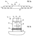
In Fig. 1a ist eine Zentriermembran 10 in einer Schnittdarstellung gezeigt. Deutlich ist dieser
Darstellung entnehmbar, daß die Zentriermembran 10 eine ziehharmonikaförmige Kontur
aufweist und zentrisch eine Öffnung 11 besitzt. Der die Öffnung 11 unmittelbar umrandende
Bereich der Zentriermembran 10 ist derjenige, welcher in dieser Anmeldung als erster
Bereich 12 bezeichnet ist. Da vorliegend die Kontur der Zentriermembran 10 ziehharmonikaförmig
ausgebildet ist, hat der erste Bereich 12 bezogen auf die Mittellinie einen schrägen
Verlauf.In Fig. 1a, a centering
In Fig. 1b ist ein Schwingspulenträger 13 gezeigt, der rohrförmig ausgebildet ist. Dieser
Schwingspulenträger 13 ist auf einem Arbeitsdorn 14 angeordnet, welcher einen vom
Schwingspulenträger 13 ummantelten Raum 15 ausfüllt und am oberen Ende 16 des
Schwingspulenträgers 13 aus diesem austritt. Nahe dem unteren Ende 17 des Schwingspulenträgers
13 ist die Schwingspule 18 am Schwingspulenträger 13 befestigt.In Fig. 1b, a
Die beiden Schwingspulendrähte 19, welche mit der Schwingspule 18 verbunden sind, sind
am Außenmantel 20 des Schwingspulenträgers 13 in Richtung dem oberen Ende 16 des
Schwingspulenträgers 13 entlang geführt und jeweils mittels eines Lötpunktes 21 mit den
gleichfalls am Außenmantel 20 des Schwingspulenträgers 13 entlang geführten Litzen 22
leitend verbunden. Das Anliegen der Spulendrähte 19, der Lötpunkte 21 und der Litzen 22
am Außenmantel 20 des Schwingspulenträgers 13 wurde dadurch erreicht, daß die Litzen 22
in am oberen Ende des Arbeitsdorns 14 angeordneten Kerben 23 fixiert und strammgezogen
wurden. Die Kerben 23 sind nur beispielhaft genannt. Vielmehr kann das Strammziehen und
Fixieren der Litzen 22 auch in einer anderen dem Fachmann geläufigen Weise erfolgen.The two
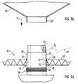
Wird nun die in Fig. 1a gezeigten Zentriermembran 10 in Pfeilrichtung P1 am oberen Ende
16 auf einen Schwingspulenträger 13 gemäß Fig. 1b aufgeschoben, stellen sich Verhältnisse
ein, die in Fig. 2a gezeigt sind. Zur besseren Darstellbarkeit ist gegenüber Fig. 1b in Fig. 2a
der Schwingspulenträger 13 um 90° in Uhrzeigerrichtung gedreht worden. Deutlich ist der
Darstellung gemäß Fig. 2a entnehmbar, daß der innere Rand 24 der Zentriermembran 10 am
Außenmantel 20 des Schwingspulenträger 13 anliegt und sich der erste Bereich 12 der
Zentriermembran 10 in Richtung zur Schwingspule 18 öffnet.
Auch ist der Darstellung gemäß Fig. 2a entnehmbar, daß der in dieser Darstellung sichtbare
Spulendraht 19, der Lötpunkt 21 und die Litze 22 am Außenmantel 20 des Schwingspulenträgers
13 anliegen, da die Litze 22 in der gezeigten Kerbe 23 fixiert und strammgezogen ist.
Der sichtbare Lötpunkt 21 liegt zwischen dem ersten Bereich 12 der Zentriermembran 10
und der Außenmantel 20 des Schwingspulenträgers 13. Die Verklebung zwischen dem
Schwingspulenträger 13, der Zentriermembran 10 und dem Leitpunkt 21 wurde so realisiert,
daß in dem Zwischenraum 25 zwischen dem ersten Bereich 12 und dem Außenmantel 20 des
Schwingspulenträgers 13 eine Klebenaht 26 ausgebildet wurde.If the centering
It can also be seen from the illustration in FIG. 2a that the
Nur der Vollständigkeit halber sei darauf hingewiesen, daß die Klebenaht 26 in einem
anderen - nicht dargestellten - Ausführungsbeispiel auch schon vor dem Aufschieben der
Zentriermembran 10 auf den Schwingspulenträger 13 bzw. dem Fixieren und Strammziehen
der Litzen 22 am Schwingspulenträger 13 ausgebildet sein kann. In diesem Fall wird dann
die Zentriermembran 10 in die Klebenaht 26 geschoben. For the sake of completeness, it should be pointed out that the
Hat die Zentriermembran 10 ihre in Fig. 2a gezeigte Endlage aufdem Schwingspulenträger
13 eingenommen und ist die Klebenaht 26 ausgebildet, sollten die Litzen 22 aus den Kerben
23 genommen bzw. in einen an deren - nicht dargestellten - Ausführungsbeispiel mit der
jeweiligen Spann- und Fixieranordnung in Pfeilrichtung P2 bogenförmig über die Oberseite
27 der Zentriermembran 10 geführt werden. Härtet dann die Klebenaht 26 aus, erhalten die
Litzen 22 schon eine gewisse Vorzugsrichtung in bezug auf ihre späteren Befestigungspunkte
am Lautsprecherkorb (alles nicht gezeigt).The centering
In Fig. 2b ist eine Membran 28 gezeigt, die einen Hals 29 aufweist. Ist der Innendurchmesser
größer/gleich dem Außendurchmesser des Schwingspulenträgers 13 und wird die Membran
28 in Pfeilrichtung P3 auf den Schwingspulenträger 13 abgesenkt, stellen sich Verhältnisse
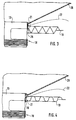
ein, welche in Fig. 3 schematisch gezeigt sind.2b shows a
In Fig. 4 ist ebenfalls schematisch eine mit der Schwingspulenträger 13 verbundenen
Membran 28 gezeigt, wobei allerdings die Zentriermembran 10 eine wellenförmige Kontur
aufweist.4 is also schematically one connected to the
Fig. 5a ist entnehmbar, daß bei einer Anordnung gemäß Fig. 3 die Litze 22 zwischen dem
Hals 29 der Membran 28 und der Zentriermembran 10 austritt und daß der Hals 29 und die
Zentriermembran 10 nahezu abstandlos in Längsrichtung des Schwingspulenträger 13
zueinander angeordnet sind.Fig. 5a can be seen that in an arrangement according to FIG. 3, the
Figur 5b, in welcher aus Gründen der Übersichtlichkeit die Klebenaht (26) nicht gezeigt ist
und in welcher aus gleichen Gründen ein geringer Abstand zwischen dem Schwingspulenträger
13, der Zentriermembran 10, der Lötpunkte 21, sowie Litze 22 und dem Hals 29 der
Membran 28 realisiert ist, zeigt daß, wenn alle eben genannten Teile vorhanden sind, die
Lötpunkte 21, die Litzen 22 und der obere Rand 24 der Zentriermembran 10 zwischen dem
Schwingspulenträger 13 und dem Hals 29 der Membran 28 angeordnet sind.Figure 5b, in which the adhesive seam (26) is not shown for reasons of clarity
and in which, for the same reasons, a small distance between the
In Fig. 5c, in welcher die Zentriermembran 10 wellenförmig ausgebildet ist, hat der obere
Rand 24 der Zentriermembran 10 zum Hals 29 der Membran 28 einen sehr geringen Abstand
in Längsrichtung des Schwingspulenträgers 13.In Fig. 5c, in which the centering
Im Gegensatz zur Darstellung gemäß Fig. 5a ist in Figur 5d der Hals 29 der Membran 28 an
der Innenseite 30 des Schwingspulenträgers 13 befestigt. Deutlich ist der Darstellung gemäß
Fig. 5a entnehmbar, daß der Hals 29 und die Klebenaht 26 bezogen auf die Längsrichtung
des Schwingspulenträgers 13 im wesentlichen in der selben Ebene angeordnet sind.In contrast to the illustration according to FIG. 5a, the
Claims (10)
dadurch gekennzeichnet,
characterized,
dadurch gekennzeichnet,
characterized by
dadurch gekennzeichnet,
characterized,
dadurch gekennzeichnet,
characterized by
dadurch gekennzeichnet,
characterized,
dadurch gekennzeichnet,
characterized,
dadurch gekennzeichnet,
characterized,
dadurch gekennzeichnet,
characterized,
dadurch gekennzeichnet,
characterized,
dadurch gekennzeichnet,
characterized,
Applications Claiming Priority (2)
| Application Number | Priority Date | Filing Date | Title |
|---|---|---|---|
| DE19711592 | 1997-03-20 | ||
| DE19711592A DE19711592A1 (en) | 1997-03-20 | 1997-03-20 | Voice coil assembly and method for making it |
Publications (2)
| Publication Number | Publication Date |
|---|---|
| EP0866636A2 true EP0866636A2 (en) | 1998-09-23 |
| EP0866636A3 EP0866636A3 (en) | 2004-09-22 |
Family
ID=7823994
Family Applications (1)
| Application Number | Title | Priority Date | Filing Date |
|---|---|---|---|
| EP98104667A Ceased EP0866636A3 (en) | 1997-03-20 | 1998-03-16 | Voice coil and method for production thereof |
Country Status (4)
| Country | Link |
|---|---|
| US (1) | US6130955A (en) |
| EP (1) | EP0866636A3 (en) |
| JP (1) | JPH1155793A (en) |
| DE (1) | DE19711592A1 (en) |
Families Citing this family (5)
| Publication number | Priority date | Publication date | Assignee | Title |
|---|---|---|---|---|
| DE19827793A1 (en) * | 1998-06-23 | 1999-12-30 | Harman Audio Electronic Sys | Voice coil assembly and method for making it |
| JP2001189994A (en) * | 1999-12-28 | 2001-07-10 | Pioneer Electronic Corp | Diaphragm for speaker and speaker system provided with diaphragm |
| JP3843939B2 (en) * | 2002-12-03 | 2006-11-08 | 松下電器産業株式会社 | Voice coil insertion jig, speaker manufacturing method using the jig, and speaker manufactured using the jig |
| US8103044B2 (en) * | 2006-08-24 | 2012-01-24 | Pioneer Corporation | Speaker device |
| US10555085B2 (en) * | 2017-06-16 | 2020-02-04 | Apple Inc. | High aspect ratio moving coil transducer |
Citations (2)
| Publication number | Priority date | Publication date | Assignee | Title |
|---|---|---|---|---|
| US2007484A (en) * | 1934-04-06 | 1935-07-09 | Magnavox Co | Sound reproducing apparatus |
| US5014323A (en) * | 1989-07-28 | 1991-05-07 | Bose Corporation | Voice coil lead dressing |
Family Cites Families (3)
| Publication number | Priority date | Publication date | Assignee | Title |
|---|---|---|---|---|
| BE412034A (en) * | 1934-12-05 | |||
| US5249236A (en) * | 1989-12-01 | 1993-09-28 | Kabushiki Kaisha Kenwood | Wiring structure of loudspeaker |
| US5641910A (en) * | 1994-06-13 | 1997-06-24 | Dynamic Instruments, Inc. | Electrodynamic transducer shaker and method for its manufacture |
-
1997
- 1997-03-20 DE DE19711592A patent/DE19711592A1/en not_active Ceased
-
1998
- 1998-03-16 EP EP98104667A patent/EP0866636A3/en not_active Ceased
- 1998-03-19 US US09/044,650 patent/US6130955A/en not_active Expired - Lifetime
- 1998-03-20 JP JP10072791A patent/JPH1155793A/en active Pending
Patent Citations (2)
| Publication number | Priority date | Publication date | Assignee | Title |
|---|---|---|---|---|
| US2007484A (en) * | 1934-04-06 | 1935-07-09 | Magnavox Co | Sound reproducing apparatus |
| US5014323A (en) * | 1989-07-28 | 1991-05-07 | Bose Corporation | Voice coil lead dressing |
Also Published As
| Publication number | Publication date |
|---|---|
| JPH1155793A (en) | 1999-02-26 |
| DE19711592A1 (en) | 1998-09-24 |
| US6130955A (en) | 2000-10-10 |
| EP0866636A3 (en) | 2004-09-22 |
Similar Documents
| Publication | Publication Date | Title |
|---|---|---|
| DE9316172U1 (en) | Sleeve for receiving branch or connection points of optical or electrical cables | |
| EP0416371B1 (en) | Optic for endoscope | |
| CH661165A5 (en) | ELECTROMECHANICAL CONVERTER WITH ADJUSTABLE ANCHOR YOC AND METHOD FOR ADJUSTING THE ANCHOR YOC. | |
| DE3404975C2 (en) | Stator for an electric motor and method for its assembly | |
| EP0866636A2 (en) | Voice coil and method for production thereof | |
| DE3331770A1 (en) | FILTER UNIT AND DETACHABLE FILTER TO CONNECT TO ANOTHER FILTER | |
| DE2512781B2 (en) | FILTER CANDLE WITH REFLECTIVE FILTER DEVICES | |
| DE3142163A1 (en) | LOOP TIE | |
| DE4419250A1 (en) | Voice coil former for loudspeakers | |
| EP0967831A2 (en) | Mobil coil device and method for its implementation | |
| DE3038905C2 (en) | Loudspeakers and process for their manufacture | |
| DE8909435U1 (en) | Armature for an electric motor | |
| DE19609168C2 (en) | Assembled decorative body, in particular decorative star, consisting of a carrier body and attached to it formed as pyramid-shaped tips parts and method for its production | |
| DE3638693A1 (en) | Compact electroacoustic transformer | |
| DE4243308C2 (en) | Dynamic electro-acoustic transducer, especially headphones | |
| DE2451895A1 (en) | Electromagnetic relay assembly - welded thermoplastic halves of coil former ensure separation of winding from contacts | |
| DE2625025A1 (en) | Terminals for coil formers - are provided in hollow compartments on one of coil former flanges | |
| DE69225557T2 (en) | Cable ladder | |
| DE2526449C3 (en) | Method for connecting plastic-sheathed cables with the aid of a sleeve | |
| DE2745183A1 (en) | ELECTRODE FORMATION OF THE ELECTRON CANNONS OF AN INLINE COLOR TUBE | |
| DE3015013A1 (en) | WARMED COAT FOR A TUBE | |
| DE2263419A1 (en) | CABLE ACCESSORY | |
| DE2414636A1 (en) | ELECTROSTATIC CONVERTER | |
| DE3228661A1 (en) | Mounting of the demagnetisation coil on colour picture tubes | |
| EP2171730B1 (en) | Electric coil |
Legal Events
| Date | Code | Title | Description |
|---|---|---|---|
| PUAI | Public reference made under article 153(3) epc to a published international application that has entered the european phase |
Free format text: ORIGINAL CODE: 0009012 |
|
| AK | Designated contracting states |
Kind code of ref document: A2 Designated state(s): AT BE CH DE DK ES FI FR GB GR IE IT LI LU MC NL PT SE |
|
| AX | Request for extension of the european patent |
Free format text: AL;LT;LV;MK;RO;SI |
|
| RAP1 | Party data changed (applicant data changed or rights of an application transferred) |
Owner name: HARMAN AUDIO ELECTRONIC SYSTEMS GMBH |
|
| PUAL | Search report despatched |
Free format text: ORIGINAL CODE: 0009013 |
|
| AK | Designated contracting states |
Kind code of ref document: A3 Designated state(s): AT BE CH DE DK ES FI FR GB GR IE IT LI LU MC NL PT SE |
|
| AX | Request for extension of the european patent |
Extension state: AL LT LV MK RO SI |
|
| 17P | Request for examination filed |
Effective date: 20041013 |
|
| AKX | Designation fees paid |
Designated state(s): AT BE CH DE DK ES FI FR GB GR IE IT LI LU MC NL PT SE |
|
| 17Q | First examination report despatched |
Effective date: 20050701 |
|
| STAA | Information on the status of an ep patent application or granted ep patent |
Free format text: STATUS: THE APPLICATION HAS BEEN REFUSED |
|
| 18R | Application refused |
Effective date: 20050902 |