EP0866434A1 - Dispositif de saisie d'objets en mouvement - Google Patents
Dispositif de saisie d'objets en mouvement Download PDFInfo
- Publication number
- EP0866434A1 EP0866434A1 EP98250052A EP98250052A EP0866434A1 EP 0866434 A1 EP0866434 A1 EP 0866434A1 EP 98250052 A EP98250052 A EP 98250052A EP 98250052 A EP98250052 A EP 98250052A EP 0866434 A1 EP0866434 A1 EP 0866434A1
- Authority
- EP
- European Patent Office
- Prior art keywords
- detection
- radio
- vehicle
- radiation
- energy
- Prior art date
- Legal status (The legal status is an assumption and is not a legal conclusion. Google has not performed a legal analysis and makes no representation as to the accuracy of the status listed.)
- Granted
Links
Images


Classifications
-
- G—PHYSICS
- G08—SIGNALLING
- G08G—TRAFFIC CONTROL SYSTEMS
- G08G1/00—Traffic control systems for road vehicles
- G08G1/01—Detecting movement of traffic to be counted or controlled
-
- G—PHYSICS
- G08—SIGNALLING
- G08G—TRAFFIC CONTROL SYSTEMS
- G08G1/00—Traffic control systems for road vehicles
- G08G1/01—Detecting movement of traffic to be counted or controlled
- G08G1/04—Detecting movement of traffic to be counted or controlled using optical or ultrasonic detectors
Definitions
- the invention relates to a device for detecting moving objects, in particular Vehicles on a lane and a detection system.
- the object of the invention creating a simple, inexpensive, easy to assemble and to be maintained as well as against damage, in particular due to vandalism unassuming arrangement.
- the device according to the invention is very universal, fast, simple and inexpensive to assemble. There is a significant cost reduction in particular from the fact that none of the usual in the prior art, for example detector mounted spatially separated above a roadway Control cabinet for power supply, fixed network communication device and other components and therefore no foundation for a control cabinet, as well No wiring of the control cabinet and detection device is required.
- the omission of a control cabinet is made possible in particular by the fact that the inventive device for data transmission to at least one Central, not as in the prior art telephone lines or other lines used, but a radio-based transmitter and in that a self-sufficient energy supply through photovoltaics. Since one of the Detection device separate control cabinet for other components not damage to parts that were previously easily accessible, such as in particular the severing of the previous cable connections from Detection device and control cabinet, as well as the also easily accessible Control cabinets avoided.
- the device according to the invention as a compact device saves space, more universal, for example on existing supporting structures, bridge railings, Tunnel entrances or other existing or possibly simple and Support elements that can be created inexpensively.
- a radio-based transmission device is generally essential less expensive than line-based communication.
- a line-based Power supply which in particular in remote areas, but also in Urban area is complex and expensive due to the self-sufficient energy supply not mandatory.
- the Energy supply through photovoltaics has the advantage over a long service life to be able to work independently and in an environmentally friendly manner with long maintenance intervals.
- the device according to the invention is thus inexpensive, self-sufficient and universal applicable.
- radio-based receiving device e.g. B. for control purposes.
- Transmitting device and receiving device can be realized in one module be.
- the device is from a central station via radio via the receiving device can be parameterized and queried remotely.
- the radio device is useful in the form of GSM or other transmission technology realized what a simple and Cost-effective integration into existing radio networks, especially into existing enables high-quality and largely nationwide mobile radio networks.
- a security device in particular in the form of a Coding of the data sent by the device and / or the use of access codes for from a center to a device according to the invention commands sent. This is an unauthorized exploitation by detected according to the invention, transmitted by radio and receivable by third parties Data or sabotage of a device due to impermissible re-parameterization, Shutdown etc. avoided by unauthorized third parties.
- a traffic monitoring system with several Devices according to the invention, each associated with a roadway, are possible.
- a detection system a device according to the invention assigned to a plurality of lanes, which thus multiple lanes synchronously using their own detectors or alternating Common detectors assigned to different lanes are monitored.
- a detection device for detecting the number of vehicles on one or more Roadways and / or vehicle speeds and / or vehicle lengths and / or vehicle types and / or vehicle identity are preferably one or several sensors of different technology are used. Techniques like Infrared (active and / or passive), laser, image acquisition, microwaves / radar or one Combination of at least two of these techniques used.
- the housing on a solar element having carrier, or attached to a bracket, each is pivotally and lockably arranged. This enables particularly simple ones Maintenance access by folding down the lower part of the holder together Detection unit. Road closures are not required for maintenance.
- An automatic adaptation of the system to the is also advantageous Mounting height, which is complex individual adjustments of each individual device saved on the individual circumstances of the respective installation site.
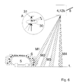
- Fig. 1 shows a schematic representation of a running across a lane 1 Bridge 2, on the railing 3, an inventive device 4 for detection of vehicles 5 traveling on the lane 1 in the direction of the arrow 5 is mounted.
- the vehicle 5 When passing a detector 4, the vehicle 5 is used by it for detection and / or speed measurement and / or identification in a measuring zone M detected. Furthermore, a wake-up zone A is indicated in the example shown; at the Passing through the wake-up zone is according to one embodiment of the invention Device "woken up" from an energy-saving inactive state, that is activated.
- the support arm 6 of the device is in the direction of arrow C opposite Mounting device 13 for maintenance on a person performing maintenance swiveling.
- the Swivel mechanism lockable to prevent the device 4 from unauthorized Fold up and protect against vandalism.
- the entire device 4 is in one over one or mountable or assembled on a carrier 6, from an upper housing part 7 and a housing lower part 8 existing housing.
- the upper housing part 7 has the power supply of the device, which here Includes photovoltaic element 9 and a battery 10.
- the illustrated Energy supply includes the photovoltaic, the battery and the charge control.
- the rotatability of the upper housing part 7 relative to the lower housing part 8 enables easy adjustment of the photovoltaic cells according to the cardinal direction for optimal use of solar energy.
- the device 4 or the detection device 12 can be moved e.g. about horizontal axis running transversely to the direction of the road for easy optimal Alignment to the roadway 1 to be pivotable.
- a radio device 11 and a detection device are in the lower housing part 8 12 arranged.
- the radio device 11 is used at least to transmit detected, the detection, speed, length and / or identification of vehicles relevant data by radio to at least one control center. It is also advisable if the radio device 11 also for receiving from a central office transmitted signals is designed; This allows data to be sent from the central office to the Device are sent, which control them, reconfigure them or Commands, especially the request to transfer data.
- the indicated radio device 11 is based on the GSM standard Radio data transmission standard or other radio transmission techniques and standards designed and thus easy and inexpensive to implement as well as for communication suitable with a control center without further adjustment.
- the detection device 12 can be based on different measurement techniques. In particular, passive / active infrared, laser, image acquisition, microwave / radar, and combination of at least two of these techniques.
- the choice of measuring techniques or measuring devices depends on the local Conditions as well as the type of data to be recorded and the required Precision.
- the detection device can be used to detect the number of vehicles, speeds, Vehicle length, identification of the vehicle type or identification of the special vehicle.
- a suitable evaluation unit including software provided in the housing. So is with Use of an image capture device such as a video camera, in particular CCD camera as detection device 12 an image processing device subordinate.
- a circuit in the form of a central control / software, measured and possibly further processed values in the form of data are transferred to the radio device 11, for example a GSM modem, and the transmission device is controlled.
- commands received from radio device 11 are taken over by a central control unit and the control is reconfigured, activated, deactivated, a measurement triggered, depending on the type of command received, and the height of the device above the roadway is to be detected automatically and on the basis of this level, the further processing of the data measured by a detection device 12 must be adjusted before sending.
- the system can also be activated by the control system on command or in definable time intervals, which can optionally be repaired via radio, so that measurements are only carried out in interval operation and further energy savings are made.
- the control can be used to predefine the interval in which transmission is carried out or to transmit the data to a special command from a control center.
- the components of the control circuit are expediently designed to be energy-saving in order to optimally utilize the limited available energy, for example using CMOS technology.
- the detection device 12 is also designed to save energy.
- the current state or status of the device 4 can be detected by the controller and transmitted by radio to the center via the radio device 11 at intervals or after a query command from the center.
- the status includes, in particular, data about the state of charge of the battery and electronically detectable defects in the photovoltaic 9 or detection device 12, etc.
- each lane can be assigned its own monitoring device 4.
- the individual devices can be implemented as a master-slave concept. In particular, in order to save energy, for example, a radio device and / or a controller can only be arranged in the master device.
- the individual devices can be connected to one another by lines or by radio, which requires little energy due to the short distance, or by light transmission in terms of information and supply technology.
- the device 4 is in the examples shown in Figures 3 and 4 via a Mounting device 13 set on the bridge railing 3.
- the bridge railing 3 is located on a road 1 extending across a roadway 1 to be measured Bridge 2.
- the device 4 consists of a rectangular housing in which the Detection device 12 with a computer part, the power supply 10 and the Transmitter unit 11 are included.
- the device 4 is in the horizontal C by one vertical axis and in the vertical D about a horizontal axis.
- the Photovoltaic panel 9 is attached to the mounting device 13.
- the Photovoltaic panel 9 can be pivoted in the direction B on the mounting device 13.
- the lower part of the assembly device 13 is closed with the detection device 4 Maintenance purposes in the direction of the bridge railing 3, that is, maintenance Executing person standing on the bridge in the direction of arrow A swiveling.
- the swivel device on the E-E axis in the form of a hinge etc.
- the swivel device on the E-E axis lockable with a special tool. This can be done through a non-commercial Special tools, such as a high-quality key respectively. Swiveling is not possible in the locked state.
- the device 4 in Figure 4 consists of a compact housing with an integrated Photovoltaic panel 9, in which the detection devices 12, the computer part, the Power supply and the transmitter unit are included.
- the device 4 is in the Alignable horizontals (B).
- the detection device 12 is in two levels C and D, so it can be swiveled horizontally and vertically.
- Fig. 5 shows a further embodiment of the invention, on a mast 14 and on an existing sign 16 assembled state.
- the device 4 is located here next to the roadway 1 on a mast 14, which by means of the foundation 15, Pile foundation or other design is anchored in the ground or on one already existing equipment such as signs 16 or gantries.
- the device 4 consists of a compact, two-part housing with an integrated photovoltaic panel 9, the detection devices 12, the computer part, the power supply 10 and the transmission unit 11 being contained in the housing.
- the device 4 can be aligned horizontally in the direction B.
- the detection devices 12 can be pivoted in two planes in the direction of the arrows C and D in the horizontal and vertical.
- the photovoltaic panel 9 can additionally be rotated horizontally and vertically in directions A and B.
- a compact detector 4 can be implemented using the sensor technologies described below with reference to FIGS. 6 to 9, which are important in connection with and independently of the invention.
- the different measuring techniques react differently to certain influencing factors. Time of day, weather and also the different vehicle types can influence the detection or accuracy.
- the following table shows particular advantages of detectors: The principles of the measuring method are first explained, then examples are described with reference to FIGS. 6 to 9.
- the detection device 12 can have a plurality of receiving devices 12b using passive IR technology include, pyroelectric (dynamic) for initial detection and for speed detection of vehicles as well as thermophilic (static) for the length determination.
- passive IR technology include, pyroelectric (dynamic) for initial detection and for speed detection of vehicles as well as thermophilic (static) for the length determination.
- Passive IR sensors are energy saving because they do not emit any energy.
- the transmitter is the respective vehicle, which represents a radiating body. Bodies that are not at absolute zero in terms of temperature (-273 ° C) radiate energy in the form of heat radiation. The intensity of the radiation depends on the temperature, the material and the surface properties. This radiation is converted into an electrical current by the sensor element for a specific frequency range. The change in radiation is evaluated on the basis of the change in current. Since the energy changes z. T. are very small and the radiation / temperature range is very large, the sensor elements must be very sensitive to changes. At the same time they have to rel. can process large amounts of energy.
- the occurrence of a certain energy level is detected by sensors that convert the energy more slowly but continuously.
- Different types of sensors are combined for applications that require quick detection, such as speed measurement, but which should also allow detection at an energy level that varies over the length of the vehicle.
- Inaccuracies in the detection result from the fact that the transmitters have no sharp radiation contours.
- Heat radiation is emitted from an area surrounding an object. This area depends on the radiation source and the surrounding medium, which can dampen this heat radiation or increase the size of the heat radiation-emitting area. In heavy traffic, these areas, e.g. B. in rain or steamy road, overlap. A separation is then difficult.
- a speed measurement is possible from> 0 km / h to> 200 km / h.
- the measurement factor is on average up to 10% and depends on the weather. It increases with speed.
- length measurement is possible with a measurement error of approx.> 1 m depending on the vehicle type, material and the load.
- a count by separating vehicles in close succession is at dry weather possible.
- An active IR sensor can work as an IR button, ie as a pulsed light barrier with transmitter 12a and receiver 12b, and detects near and far fields. This makes it possible to avoid incorrect or non-detection, which occurs due to the different reflection properties of the vehicle surfaces.
- the sensor can be used in particular in combination with a radar sensor.
- the active IR sensor consists of two components, an IR transmitter and an IR receiver.
- the required IR transmission energy depends on the mounting height and reflection properties of the background, because with this method the transmission energy emitted by the transmitter, continuously or in a pulsed manner, is emitted by an object, e.g. B. a vehicle or a street, depending on the surface more or less diffusely or directionally reflected.
- the attenuation increases quadratically with the distance to the reflector.
- the IR diodes generate the necessary radiation power, they are operated in pulse mode. They can briefly emit up to 10 times the permitted radiation power. For a good utilization of the energy, the radiation is strongly bundled by means of optical lenses. If only one light barrier is used, there is a great risk that vehicles will pass it without reliable detection. If only one light barrier is used, speed measurement is not possible. Heavy precipitation, especially heavy snow, which limits the view to less than 50 m, can influence the measured values. Measurements from the side are only possible to a limited extent due to the reflection detection with near and far fields. A length measurement is only possible with the aid of the measured speed with a deviation of up to 0.5 m and is also dependent on the speed accuracy of the detector. The recording / counting is generally good and independent of the weather, even in vehicles closely following one another, due to the strong concentration of the radiation.
- Double active IR Double active IR:
- An active IR sensor works, for example, as a double IR light barrier.
- the speed measurement is possible from> 0 km / h to> 200 km / h.
- the deviation is less than 20%, depending on the structure chosen Vehicle type and increases with speed.
- a length measurement is basically possible.
- Microwave / radar according to FIG. 8 Microwave / radar according to FIG. 8:
- a radar sensor evaluates the reflection of the radar pulses emitted based on the Doppler frequency shift and possibly an energy measurement and uses them to determine vehicle speeds and types.
- the system can evaluate up to 40 measurements per vehicle. Standing traffic is not recognized.
- the radar signal for example at 24 GHz or 64 GHz, is emitted continuously, depending on the system, continuously or only for the transit time of a vehicle. The radar signal cannot be switched as quickly as desired due to the transient and decay processes.
- Radar evaluates the frequency and spectrum of the signal, which are changed during reflection due to the movement of the object relative to the transmitter. Evaluations of the reflected energy allow statements about the vehicle size / shape.
- the radar radiation is influenced by precipitation.
- Precipitation can reflect / scatter the radiation, which leads to an attenuation of the radiation or a Doppler shift.
- Known spectral components of the resulting reflection components can be filtered out, for example, by high / low / band passes.
- the attenuation is compensated for by more radiation energy, whereby radiation limit values must be observed. Measurements from the side are possible, but should then be carried out like a radar measurement by the police from the side at vehicle height, so that there is a uniform surface on all vehicles and almost no shift in the reflection plane.
- the illuminated surface of the vehicles can be problematic, namely partly the side, partly the roof. This results in considerable differences in the reflected energy and the reflection plane gets an additional speed component. A speed and type statement is then only very imprecise.
- An overhead measurement is possible from 5 km / h to> 200 km / h.
- the deviation is on average up to 3%, but increases at very low speeds.
- a length or type detection is possible by evaluating the reflection energy and the reflection duration. The counting in very closely following vehicles is difficult due to the radiation area and the necessary radiation angle.
- Systems can consist, for example, of two IR transmitters that radiate downwards in parallel.
- the vehicle speed, the vehicle type and the vehicle length are recorded by means of correlation (pattern recognition), envelope curve and time difference methods.
- pattern recognition pattern recognition
- envelope curve envelope curve
- time difference methods By deflecting / fanning the beam, the entire width of the road can be detected.
- the beam is only fanned out in width, which only slightly reduces the detection accuracy.
- the reflection R can be evaluated by means of, for example, triangulation and additionally, for example, by means of contour pattern recognition.
- the second sensor recognizes a certain point of the vehicle through the pattern recognition, and thus the time measurement is carried out very precisely.
- the contour recognition allows a detailed assignment of vehicle types.
- Measurements from the side are possible, although shading is important.
- the speed measurement is possible from> 0 km / h to> 200 km / h.
- the average deviation is ⁇ 3%.
- a length measurement is possible with a deviation in the cm range.
- the counting of vehicles in close succession is possible precisely.
- Video evaluation systems have a very powerful computer, depending on the need for detection. With the help of pattern or image comparisons, people, vehicles or objects are recognized and position, size, type and number recorded in time. Color distinctions are also possible. Correlation methods and FUZZI logic are used. Large data stores are necessary. Measurements from the side are favorable for the vehicle type and length detection, whereby shading must be taken into account. A speed and length evaluation is possible depending on exposure times and the number of pictures taken per second from> 0 km / h to> 200 km / h. It is easy to count vehicles closely following one another. The quality depends on the perspective.
- the passive IR system detection system 4, 12b shown in FIG. 6 detects the radiation of a vehicle for speed determination in several IR measurement zones M1 to M3.
- the radiation is detected in a pyroelectric measuring zone M4 for determining the length of the object.
- the emitter is object 5, which emits radiation S in the form of heat. The intensity is not evenly distributed.
- Measurement errors occur here in that for high vehicles 5 the distance between zones M1 to M4 is smaller than for low ones; these measuring errors are reduced by a large mounting height and / or arranging the zones M1 ... M4 approximately vertically below the transmitter, in particular at the greatest possible distance from one another.
- Another problem is that the different areas of the vehicles 5 radiate very differently and the object radiation S can assume values of the road radiation, which is why high sensor sensitivity of the IR sensors 12b is selected with a large actuation range at the same time. A division of the radiation spectrum S may be necessary.
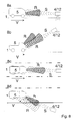
- FIG. 8a shows a side view of a microwave radar measurement from the roadside
- 8b shows an overhead measurement in side view
- FIG. 8c shows a top view Overhead measurement
- Fig. 8d in plan view a measurement from the roadside.
- the signal S emitted by the transmission component of the detector 12 is transmitted Object 5 reflected. Due to the movement in the direction V of the reflective Object 5, the frequency of the reflected signal R is changed and by means of Receiver unit of the detector 12 detected. The frequency change is proportional to the Speed V of the object.
- the frequency change is different.
- the change in the angle of the reflection surface to the radar affects the frequency. Because of different angles of the reflection surface for each object 5 and, in addition, protruding and recessed surfaces, several measurements from the side and / or an evaluation of a large number of measurements per object are carried out.
- the transmitted radiation S is in phase and strongly bundled.
- the radiation is directed or diffusely reflected (R) according to FIG. 9a.
- the transmission beam S can be fanned out according to FIG. 9b by means of rotating mirrors.
- a surface profile 5 can be created and the speed determined by a runtime evaluation of the modulated signal S / R fanned out in two levels.
- a surface profile 5 can be created by fanning out in one plane and height detection according to FIG. 9c. It is not possible to determine the speed. In the case of a system with two transmission and reception components in a detector 12 according to FIG. 9d, however, speed detection can be carried out without beam deflection.
- the change in the reflection plane height is determined twice using triangulation.
- An exact speed V and object length can be detected via a pattern recognition of the reflected signal R.
Applications Claiming Priority (4)
| Application Number | Priority Date | Filing Date | Title |
|---|---|---|---|
| DE19708470 | 1997-02-19 | ||
| DE19708470 | 1997-02-19 | ||
| DE19729915A DE19729915A1 (de) | 1997-02-19 | 1997-07-04 | Vorrichtung und Erfassung bewegter Objekte |
| DE19729915 | 1997-07-04 |
Publications (2)
| Publication Number | Publication Date |
|---|---|
| EP0866434A1 true EP0866434A1 (fr) | 1998-09-23 |
| EP0866434B1 EP0866434B1 (fr) | 2004-06-16 |
Family
ID=26034441
Family Applications (1)
| Application Number | Title | Priority Date | Filing Date |
|---|---|---|---|
| EP98250052A Expired - Lifetime EP0866434B1 (fr) | 1997-02-19 | 1998-02-16 | Dispositif de saisie d'objets en mouvement |
Country Status (2)
| Country | Link |
|---|---|
| EP (1) | EP0866434B1 (fr) |
| AT (1) | ATE269569T1 (fr) |
Cited By (14)
| Publication number | Priority date | Publication date | Assignee | Title |
|---|---|---|---|---|
| WO2001035372A1 (fr) * | 1999-11-09 | 2001-05-17 | C.R.A.F.T. S.R.L. | Systeme de surveillance de trafic de vehicules sur des routes et des autoroutes |
| EP1296302A1 (fr) * | 2001-09-20 | 2003-03-26 | Alma Mater Studiorum -Universita' di Bologna | Système, unité centrale et procédé de surveillance du trafic |
| WO2003036320A2 (fr) * | 2001-09-29 | 2003-05-01 | Vitronic Dr.-Ing. Stein Bildverareitungssysteme Gmbh | Procede et dispositif de mesure des vitesses d'objets en mouvement |
| WO2007036088A1 (fr) * | 2005-09-30 | 2007-04-05 | Dova Laser Technologies Co., Ltd. | Detecteur de vehicule laser |
| EP1975642A1 (fr) * | 2007-03-29 | 2008-10-01 | ROBOT Visual Systems GmbH | Appareil de surveillance du trafic doté d'un boîtier d'appareil équipé d'un tiroir enfichable vertical |
| CH700149A1 (fr) * | 2008-12-23 | 2010-06-30 | Dzotec Sa | Dispositif radar autonome électriquement. |
| WO2012001332A1 (fr) | 2010-07-01 | 2012-01-05 | Neavia Technologies | Dispositif de surveillance |
| EP2905764A1 (fr) * | 2014-02-10 | 2015-08-12 | Park 24 | Détecteur magnétique-radar hybride pour gestion d'espace |
| CN106710237A (zh) * | 2017-03-31 | 2017-05-24 | 广州维脉电子科技有限公司 | 一种便携式路侧激光交通调查装置及其调查方法 |
| DE102016109148A1 (de) * | 2016-05-18 | 2017-11-23 | Jenoptik Robot Gmbh | Mautkontrollgerät für eine Trägerplattform, Sondersignalanlage, Mautkontrollsystem und Verfahren zum Kontrollieren einer Mautzahlung |
| US10488492B2 (en) | 2014-09-09 | 2019-11-26 | Leddarttech Inc. | Discretization of detection zone |
| USRE48763E1 (en) | 2011-05-11 | 2021-10-05 | Leddartech Inc. | Multiple-field-of-view scannerless optical rangefinder in high ambient background light |
| USRE48914E1 (en) | 2012-03-02 | 2022-02-01 | Leddartech Inc. | System and method for multipurpose traffic detection and characterization |
| USRE49342E1 (en) | 2007-12-21 | 2022-12-20 | Leddartech Inc. | Distance detection method and system |
Families Citing this family (10)
| Publication number | Priority date | Publication date | Assignee | Title |
|---|---|---|---|---|
| US8242476B2 (en) | 2005-12-19 | 2012-08-14 | Leddartech Inc. | LED object detection system and method combining complete reflection traces from individual narrow field-of-view channels |
| US8600656B2 (en) | 2007-06-18 | 2013-12-03 | Leddartech Inc. | Lighting system with driver assistance capabilities |
| US8436748B2 (en) | 2007-06-18 | 2013-05-07 | Leddartech Inc. | Lighting system with traffic management capabilities |
| WO2009079779A1 (fr) | 2007-12-21 | 2009-07-02 | Leddartech Inc. | Système et procédé de gestion de stationnement utilisant un système d'éclairage |
| DE202008003979U1 (de) | 2008-03-20 | 2008-06-26 | Fraas, Alfred, Dipl.-Ing. | Messsystem für die Verkehrsstromanalyse |
| EP2517189B1 (fr) | 2009-12-22 | 2014-03-19 | Leddartech Inc. | Système de surveillance 3d actif pour une détection de trafic |
| DE102010013878A1 (de) | 2010-02-16 | 2011-08-18 | Niechoj electronic GmbH, 88085 | Fahrbahnintegrierter Radarsensor |
| WO2012172526A1 (fr) | 2011-06-17 | 2012-12-20 | Leddartech Inc. | Système et procédé de détection latérale et de caractérisation de circulation |
| CN104662442B (zh) | 2013-08-16 | 2018-02-09 | 飞利浦灯具控股公司 | 用于检测杆的物理变形的系统和方法 |
| GB201400055D0 (en) * | 2014-01-03 | 2014-02-19 | Cycle Alert Holdings Ltd | Low power position detecting system |
Citations (7)
| Publication number | Priority date | Publication date | Assignee | Title |
|---|---|---|---|---|
| GB2025185A (en) * | 1978-07-05 | 1980-01-16 | Siemens Ag | Vehicle location system |
| DE3706229A1 (de) | 1986-09-13 | 1988-03-24 | Klaus Lindemann | Elektronisches beleuchtungsschaltsystem |
| EP0289657A2 (fr) * | 1986-11-27 | 1988-11-09 | Sumitomo Electric Industries Limited | Système de balises routières à rayons polarisés |
| US4985705A (en) * | 1988-03-26 | 1991-01-15 | Telefunken Systemtechnik Gmbh | Method and apparatus for compiling and evaluating local traffic data |
| JPH05297097A (ja) * | 1991-12-16 | 1993-11-12 | Sumitomo Electric Ind Ltd | 路側ビーコン装置 |
| DE4300650A1 (de) | 1993-01-08 | 1994-07-14 | Refit Ev | Verfahren zur Ermittlung von fahrzeugklassenbezogenen Verkehrsflußdaten |
| EP0694895A2 (fr) * | 1994-07-18 | 1996-01-31 | Sumitomo Electric Industries, Inc. | Dispositif embarqué d'affichage de route recevant des informations d'un appareil externe |
-
1998
- 1998-02-16 EP EP98250052A patent/EP0866434B1/fr not_active Expired - Lifetime
- 1998-02-16 AT AT98250052T patent/ATE269569T1/de not_active IP Right Cessation
Patent Citations (7)
| Publication number | Priority date | Publication date | Assignee | Title |
|---|---|---|---|---|
| GB2025185A (en) * | 1978-07-05 | 1980-01-16 | Siemens Ag | Vehicle location system |
| DE3706229A1 (de) | 1986-09-13 | 1988-03-24 | Klaus Lindemann | Elektronisches beleuchtungsschaltsystem |
| EP0289657A2 (fr) * | 1986-11-27 | 1988-11-09 | Sumitomo Electric Industries Limited | Système de balises routières à rayons polarisés |
| US4985705A (en) * | 1988-03-26 | 1991-01-15 | Telefunken Systemtechnik Gmbh | Method and apparatus for compiling and evaluating local traffic data |
| JPH05297097A (ja) * | 1991-12-16 | 1993-11-12 | Sumitomo Electric Ind Ltd | 路側ビーコン装置 |
| DE4300650A1 (de) | 1993-01-08 | 1994-07-14 | Refit Ev | Verfahren zur Ermittlung von fahrzeugklassenbezogenen Verkehrsflußdaten |
| EP0694895A2 (fr) * | 1994-07-18 | 1996-01-31 | Sumitomo Electric Industries, Inc. | Dispositif embarqué d'affichage de route recevant des informations d'un appareil externe |
Non-Patent Citations (2)
| Title |
|---|
| PATENT ABSTRACTS OF JAPAN vol. 018, no. 092 (P - 1693) 15 February 1994 (1994-02-15) * |
| SODEIKAT M H: "SYSTEME UNIVERSEL D'INFORMATION DU VEHICULE UNIVERSAL VEHICLE INFORMATION SYSTEM", INGENIEURS DE L'AUTOMOBILE, no. 687, 1 March 1994 (1994-03-01), pages 38 - 40, XP000435035 * |
Cited By (19)
| Publication number | Priority date | Publication date | Assignee | Title |
|---|---|---|---|---|
| WO2001035372A1 (fr) * | 1999-11-09 | 2001-05-17 | C.R.A.F.T. S.R.L. | Systeme de surveillance de trafic de vehicules sur des routes et des autoroutes |
| EP1296302A1 (fr) * | 2001-09-20 | 2003-03-26 | Alma Mater Studiorum -Universita' di Bologna | Système, unité centrale et procédé de surveillance du trafic |
| WO2003036320A2 (fr) * | 2001-09-29 | 2003-05-01 | Vitronic Dr.-Ing. Stein Bildverareitungssysteme Gmbh | Procede et dispositif de mesure des vitesses d'objets en mouvement |
| WO2003036320A3 (fr) * | 2001-09-29 | 2003-07-24 | Vitronic Dr Ing Stein Bildvera | Procede et dispositif de mesure des vitesses d'objets en mouvement |
| WO2007036088A1 (fr) * | 2005-09-30 | 2007-04-05 | Dova Laser Technologies Co., Ltd. | Detecteur de vehicule laser |
| EP1975642A1 (fr) * | 2007-03-29 | 2008-10-01 | ROBOT Visual Systems GmbH | Appareil de surveillance du trafic doté d'un boîtier d'appareil équipé d'un tiroir enfichable vertical |
| USRE49342E1 (en) | 2007-12-21 | 2022-12-20 | Leddartech Inc. | Distance detection method and system |
| USRE49950E1 (en) | 2007-12-21 | 2024-04-30 | Leddartech Inc. | Distance detection method and system |
| CH700149A1 (fr) * | 2008-12-23 | 2010-06-30 | Dzotec Sa | Dispositif radar autonome électriquement. |
| WO2010072796A1 (fr) * | 2008-12-23 | 2010-07-01 | Dzotec Sa | Dispositif radar autonome électriquement |
| WO2012001332A1 (fr) | 2010-07-01 | 2012-01-05 | Neavia Technologies | Dispositif de surveillance |
| USRE48763E1 (en) | 2011-05-11 | 2021-10-05 | Leddartech Inc. | Multiple-field-of-view scannerless optical rangefinder in high ambient background light |
| USRE48914E1 (en) | 2012-03-02 | 2022-02-01 | Leddartech Inc. | System and method for multipurpose traffic detection and characterization |
| US10551489B2 (en) | 2014-02-10 | 2020-02-04 | Circet | Hybrid magnetic-radar detector for space management |
| WO2015118084A1 (fr) * | 2014-02-10 | 2015-08-13 | Park24 | Détecteur hybride magnétique-radar pour gestion d'espace |
| EP2905764A1 (fr) * | 2014-02-10 | 2015-08-12 | Park 24 | Détecteur magnétique-radar hybride pour gestion d'espace |
| US10488492B2 (en) | 2014-09-09 | 2019-11-26 | Leddarttech Inc. | Discretization of detection zone |
| DE102016109148A1 (de) * | 2016-05-18 | 2017-11-23 | Jenoptik Robot Gmbh | Mautkontrollgerät für eine Trägerplattform, Sondersignalanlage, Mautkontrollsystem und Verfahren zum Kontrollieren einer Mautzahlung |
| CN106710237A (zh) * | 2017-03-31 | 2017-05-24 | 广州维脉电子科技有限公司 | 一种便携式路侧激光交通调查装置及其调查方法 |
Also Published As
| Publication number | Publication date |
|---|---|
| EP0866434B1 (fr) | 2004-06-16 |
| ATE269569T1 (de) | 2004-07-15 |
Similar Documents
| Publication | Publication Date | Title |
|---|---|---|
| EP0866434B1 (fr) | Dispositif de saisie d'objets en mouvement | |
| DE60032675T2 (de) | Antennenanordnung für Strassen | |
| EP0335009A2 (fr) | Procédé pour acquérir et traiter des données de trafic local et dispositif pour exécuter le procédé | |
| DE102009013841A1 (de) | Messsystem für die Verkehrsstromanalyse | |
| EP3440654B1 (fr) | Procédé et système de détection de véhicules stationnés | |
| JPH06194443A (ja) | 1つ以上の車両交通調査パラメータの計算用システム | |
| WO1998035330A1 (fr) | Dispositif de detection de vehicules | |
| DE202012103986U1 (de) | Komplex zur Videofixierung und Messung von Geschwindigkeit und Koordinaten von Fahrzeugen | |
| DE102016111222A1 (de) | Windparkflugbefeuerungssystem sowie Windpark damit und Verfahren zur Befeuerung eines Windparks | |
| WO2020224876A9 (fr) | Procédé de détection d'usagers de la voie publique | |
| WO2018177887A1 (fr) | Système radar muni d'un dispositif de dégagement | |
| DE2627493B2 (de) | Schranke zum Unterscheiden und Zählen von sich bewegenden Fahrzeugen | |
| CN111596293A (zh) | 一种雷达安防一体机及其监测方法 | |
| DE102013004463B4 (de) | Vorrichtung und Verfahren zur Detektion von Flugobjekten im Umkreis von Windkraftanlagen | |
| CN204463274U (zh) | 一种倾斜单激光行人检测装置 | |
| DE19729915A1 (de) | Vorrichtung und Erfassung bewegter Objekte | |
| DE102009060499A1 (de) | Verfahren und Anordnung zur Erfassung von Verkehrsverstößen in einem Ampelbereich | |
| DE3902582C2 (de) | Verfahren zur lokalen Verkehrsdatenerfassung und -auswertung | |
| EP0594797A1 (fr) | Procede pour la surveillance d'une zone. | |
| DE4102460A1 (de) | Verfahren und einrichtung zur erfassung von fahrzeugen im strassenverkehr fuer die steuerung einer verkehrssignalanlage | |
| DE102016202608A1 (de) | Verkehrsüberwachungssystem mit einer Wellenleiteinrichtung zur Überwachung einer Verkehrsfläche | |
| DE2526753C3 (de) | Verfahren und Anordnung zur Deformationsmessung großer Objekte durch Laserstrahlreflexion | |
| EP0866433B1 (fr) | Dispositif de retransmission, à au moins un terminal, d'informations reçues sur la circulation transmises par un centre ou une unité de collecte de données | |
| EP1022923B1 (fr) | Methode d'acquisition et de traitement de donnees de trafic telematique | |
| EP1916642A1 (fr) | Dispositif pour la mesure de trafic |
Legal Events
| Date | Code | Title | Description |
|---|---|---|---|
| PUAI | Public reference made under article 153(3) epc to a published international application that has entered the european phase |
Free format text: ORIGINAL CODE: 0009012 |
|
| AK | Designated contracting states |
Kind code of ref document: A1 Designated state(s): AT BE CH DE DK ES FI FR GB GR IE IT LI LU MC NL PT SE |
|
| AX | Request for extension of the european patent |
Free format text: AL;LT;LV;MK;RO;SI |
|
| 17P | Request for examination filed |
Effective date: 19990111 |
|
| AKX | Designation fees paid |
Free format text: AT BE CH DE DK ES FI FR GB GR IE IT LI LU MC NL PT SE |
|
| RBV | Designated contracting states (corrected) |
Designated state(s): AT BE CH DE DK ES FI FR GB GR IE IT LI LU MC NL PT SE |
|
| 17Q | First examination report despatched |
Effective date: 20010606 |
|
| TPAD | Observations filed by third parties |
Free format text: ORIGINAL CODE: EPIDOS TIPA |
|
| RAP1 | Party data changed (applicant data changed or rights of an application transferred) |
Owner name: VODAFONE AG |
|
| RAP1 | Party data changed (applicant data changed or rights of an application transferred) |
Owner name: VODAFONE HOLDING GMBH |
|
| GRAP | Despatch of communication of intention to grant a patent |
Free format text: ORIGINAL CODE: EPIDOSNIGR1 |
|
| RIC1 | Information provided on ipc code assigned before grant |
Ipc: 7G 08G 1/04 B Ipc: 7G 08G 1/01 A |
|
| RAP1 | Party data changed (applicant data changed or rights of an application transferred) |
Owner name: ATX EUROPE GMBH |
|
| GRAS | Grant fee paid |
Free format text: ORIGINAL CODE: EPIDOSNIGR3 |
|
| GRAA | (expected) grant |
Free format text: ORIGINAL CODE: 0009210 |
|
| AK | Designated contracting states |
Kind code of ref document: B1 Designated state(s): AT BE CH DE DK ES FI FR GB GR IE IT LI LU MC NL PT SE |
|
| PG25 | Lapsed in a contracting state [announced via postgrant information from national office to epo] |
Ref country code: NL Free format text: LAPSE BECAUSE OF FAILURE TO SUBMIT A TRANSLATION OF THE DESCRIPTION OR TO PAY THE FEE WITHIN THE PRESCRIBED TIME-LIMIT Effective date: 20040616 Ref country code: IT Free format text: LAPSE BECAUSE OF FAILURE TO SUBMIT A TRANSLATION OF THE DESCRIPTION OR TO PAY THE FEE WITHIN THE PRE;WARNING: LAPSES OF ITALIAN PATENTS WITH EFFECTIVE DATE BEFORE 2007 MAY HAVE OCCURRED AT ANY TIME BEFORE 2007. THE CORRECT EFFECTIVE DATE MAY BE DIFFERENT FROM THE ONE RECORDED.SCRIBED TIME-LIMIT Effective date: 20040616 Ref country code: IE Free format text: LAPSE BECAUSE OF FAILURE TO SUBMIT A TRANSLATION OF THE DESCRIPTION OR TO PAY THE FEE WITHIN THE PRESCRIBED TIME-LIMIT Effective date: 20040616 Ref country code: GB Free format text: LAPSE BECAUSE OF FAILURE TO SUBMIT A TRANSLATION OF THE DESCRIPTION OR TO PAY THE FEE WITHIN THE PRESCRIBED TIME-LIMIT Effective date: 20040616 Ref country code: FR Free format text: LAPSE BECAUSE OF NON-PAYMENT OF DUE FEES Effective date: 20040616 Ref country code: FI Free format text: LAPSE BECAUSE OF FAILURE TO SUBMIT A TRANSLATION OF THE DESCRIPTION OR TO PAY THE FEE WITHIN THE PRESCRIBED TIME-LIMIT Effective date: 20040616 |
|
| REG | Reference to a national code |
Ref country code: GB Ref legal event code: FG4D Free format text: NOT ENGLISH |
|
| REG | Reference to a national code |
Ref country code: CH Ref legal event code: EP |
|
| REF | Corresponds to: |
Ref document number: 59811557 Country of ref document: DE Date of ref document: 20040722 Kind code of ref document: P |
|
| REG | Reference to a national code |
Ref country code: IE Ref legal event code: FG4D Free format text: GERMAN |
|
| RAP2 | Party data changed (patent owner data changed or rights of a patent transferred) |
Owner name: ATX EUROPE GMBH |
|
| PG25 | Lapsed in a contracting state [announced via postgrant information from national office to epo] |
Ref country code: SE Free format text: LAPSE BECAUSE OF FAILURE TO SUBMIT A TRANSLATION OF THE DESCRIPTION OR TO PAY THE FEE WITHIN THE PRESCRIBED TIME-LIMIT Effective date: 20040916 Ref country code: GR Free format text: LAPSE BECAUSE OF FAILURE TO SUBMIT A TRANSLATION OF THE DESCRIPTION OR TO PAY THE FEE WITHIN THE PRESCRIBED TIME-LIMIT Effective date: 20040916 Ref country code: DK Free format text: LAPSE BECAUSE OF FAILURE TO SUBMIT A TRANSLATION OF THE DESCRIPTION OR TO PAY THE FEE WITHIN THE PRESCRIBED TIME-LIMIT Effective date: 20040916 |
|
| PG25 | Lapsed in a contracting state [announced via postgrant information from national office to epo] |
Ref country code: ES Free format text: LAPSE BECAUSE OF FAILURE TO SUBMIT A TRANSLATION OF THE DESCRIPTION OR TO PAY THE FEE WITHIN THE PRESCRIBED TIME-LIMIT Effective date: 20040927 |
|
| NLT2 | Nl: modifications (of names), taken from the european patent patent bulletin |
Owner name: ATX EUROPE GMBH |
|
| NLV1 | Nl: lapsed or annulled due to failure to fulfill the requirements of art. 29p and 29m of the patents act | ||
| GBV | Gb: ep patent (uk) treated as always having been void in accordance with gb section 77(7)/1977 [no translation filed] |
Effective date: 20040616 |
|
| REG | Reference to a national code |
Ref country code: IE Ref legal event code: FD4D |
|
| PG25 | Lapsed in a contracting state [announced via postgrant information from national office to epo] |
Ref country code: LU Free format text: LAPSE BECAUSE OF NON-PAYMENT OF DUE FEES Effective date: 20050216 Ref country code: AT Free format text: LAPSE BECAUSE OF NON-PAYMENT OF DUE FEES Effective date: 20050216 |
|
| PG25 | Lapsed in a contracting state [announced via postgrant information from national office to epo] |
Ref country code: MC Free format text: LAPSE BECAUSE OF NON-PAYMENT OF DUE FEES Effective date: 20050228 Ref country code: LI Free format text: LAPSE BECAUSE OF NON-PAYMENT OF DUE FEES Effective date: 20050228 Ref country code: CH Free format text: LAPSE BECAUSE OF NON-PAYMENT OF DUE FEES Effective date: 20050228 Ref country code: BE Free format text: LAPSE BECAUSE OF NON-PAYMENT OF DUE FEES Effective date: 20050228 |
|
| PLBE | No opposition filed within time limit |
Free format text: ORIGINAL CODE: 0009261 |
|
| STAA | Information on the status of an ep patent application or granted ep patent |
Free format text: STATUS: NO OPPOSITION FILED WITHIN TIME LIMIT |
|
| 26N | No opposition filed |
Effective date: 20050317 |
|
| EN | Fr: translation not filed | ||
| BERE | Be: lapsed |
Owner name: *ATX EUROPE G.M.B.H. Effective date: 20050228 |
|
| REG | Reference to a national code |
Ref country code: CH Ref legal event code: PL |
|
| BERE | Be: lapsed |
Owner name: *ATX EUROPE G.M.B.H. Effective date: 20050228 |
|
| PG25 | Lapsed in a contracting state [announced via postgrant information from national office to epo] |
Ref country code: PT Free format text: LAPSE BECAUSE OF NON-PAYMENT OF DUE FEES Effective date: 20041116 |
|
| REG | Reference to a national code |
Ref country code: DE Ref legal event code: R119 Ref document number: 59811557 Country of ref document: DE |
|
| REG | Reference to a national code |
Ref country code: DE Ref legal event code: R119 Ref document number: 59811557 Country of ref document: DE Effective date: 20140902 |
|
| PG25 | Lapsed in a contracting state [announced via postgrant information from national office to epo] |
Ref country code: DE Free format text: LAPSE BECAUSE OF NON-PAYMENT OF DUE FEES Effective date: 20140902 |
|
| REG | Reference to a national code |
Ref country code: DE Ref legal event code: R073 Ref document number: 59811557 Country of ref document: DE |
|
| REG | Reference to a national code |
Ref country code: DE Ref legal event code: R074 Ref document number: 59811557 Country of ref document: DE |
|
| REG | Reference to a national code |
Ref country code: DE Ref legal event code: R074 Ref document number: 59811557 Country of ref document: DE Effective date: 20150613 |
|
| PGFP | Annual fee paid to national office [announced via postgrant information from national office to epo] |
Ref country code: DE Payment date: 20150518 Year of fee payment: 18 |
|
| PGRI | Patent reinstated in contracting state [announced from national office to epo] |
Ref country code: DE Effective date: 20150610 |
|
| REG | Reference to a national code |
Ref country code: DE Ref legal event code: R119 Ref document number: 59811557 Country of ref document: DE |
|
| PG25 | Lapsed in a contracting state [announced via postgrant information from national office to epo] |
Ref country code: DE Free format text: LAPSE BECAUSE OF NON-PAYMENT OF DUE FEES Effective date: 20160901 |