EP0866262A2 - Electrically operated apparatus for spotlight - Google Patents
Electrically operated apparatus for spotlight Download PDFInfo
- Publication number
- EP0866262A2 EP0866262A2 EP98105133A EP98105133A EP0866262A2 EP 0866262 A2 EP0866262 A2 EP 0866262A2 EP 98105133 A EP98105133 A EP 98105133A EP 98105133 A EP98105133 A EP 98105133A EP 0866262 A2 EP0866262 A2 EP 0866262A2
- Authority
- EP
- European Patent Office
- Prior art keywords
- cable
- holding device
- section
- deflecting
- cable section
- Prior art date
- Legal status (The legal status is an assumption and is not a legal conclusion. Google has not performed a legal analysis and makes no representation as to the accuracy of the status listed.)
- Granted
Links
- 230000005540 biological transmission Effects 0.000 claims description 27
- 230000002441 reversible effect Effects 0.000 claims description 17
- 230000033001 locomotion Effects 0.000 claims description 5
- 230000002093 peripheral effect Effects 0.000 claims description 4
- 238000005286 illumination Methods 0.000 abstract 1
- 230000015572 biosynthetic process Effects 0.000 description 3
- 230000000295 complement effect Effects 0.000 description 2
- 238000010276 construction Methods 0.000 description 2
- 230000000694 effects Effects 0.000 description 2
- 238000004519 manufacturing process Methods 0.000 description 2
- 239000000463 material Substances 0.000 description 2
- 230000006835 compression Effects 0.000 description 1
- 238000007906 compression Methods 0.000 description 1
- 230000001419 dependent effect Effects 0.000 description 1
- 238000009826 distribution Methods 0.000 description 1
- 230000002349 favourable effect Effects 0.000 description 1
- 238000009434 installation Methods 0.000 description 1
- 238000012423 maintenance Methods 0.000 description 1
- 239000002184 metal Substances 0.000 description 1
- 230000003287 optical effect Effects 0.000 description 1
- 238000005096 rolling process Methods 0.000 description 1
- 238000007665 sagging Methods 0.000 description 1
- 238000003860 storage Methods 0.000 description 1
- 239000006228 supernatant Substances 0.000 description 1
Images


Classifications
-
- F—MECHANICAL ENGINEERING; LIGHTING; HEATING; WEAPONS; BLASTING
- F21—LIGHTING
- F21V—FUNCTIONAL FEATURES OR DETAILS OF LIGHTING DEVICES OR SYSTEMS THEREOF; STRUCTURAL COMBINATIONS OF LIGHTING DEVICES WITH OTHER ARTICLES, NOT OTHERWISE PROVIDED FOR
- F21V27/00—Cable-stowing arrangements structurally associated with lighting devices, e.g. reels
-
- F—MECHANICAL ENGINEERING; LIGHTING; HEATING; WEAPONS; BLASTING
- F21—LIGHTING
- F21S—NON-PORTABLE LIGHTING DEVICES; SYSTEMS THEREOF; VEHICLE LIGHTING DEVICES SPECIALLY ADAPTED FOR VEHICLE EXTERIORS
- F21S10/00—Lighting devices or systems producing a varying lighting effect
-
- F—MECHANICAL ENGINEERING; LIGHTING; HEATING; WEAPONS; BLASTING
- F21—LIGHTING
- F21V—FUNCTIONAL FEATURES OR DETAILS OF LIGHTING DEVICES OR SYSTEMS THEREOF; STRUCTURAL COMBINATIONS OF LIGHTING DEVICES WITH OTHER ARTICLES, NOT OTHERWISE PROVIDED FOR
- F21V14/00—Controlling the distribution of the light emitted by adjustment of elements
-
- F—MECHANICAL ENGINEERING; LIGHTING; HEATING; WEAPONS; BLASTING
- F21—LIGHTING
- F21V—FUNCTIONAL FEATURES OR DETAILS OF LIGHTING DEVICES OR SYSTEMS THEREOF; STRUCTURAL COMBINATIONS OF LIGHTING DEVICES WITH OTHER ARTICLES, NOT OTHERWISE PROVIDED FOR
- F21V17/00—Fastening of component parts of lighting devices, e.g. shades, globes, refractors, reflectors, filters, screens, grids or protective cages
- F21V17/02—Fastening of component parts of lighting devices, e.g. shades, globes, refractors, reflectors, filters, screens, grids or protective cages with provision for adjustment
-
- F—MECHANICAL ENGINEERING; LIGHTING; HEATING; WEAPONS; BLASTING
- F21—LIGHTING
- F21V—FUNCTIONAL FEATURES OR DETAILS OF LIGHTING DEVICES OR SYSTEMS THEREOF; STRUCTURAL COMBINATIONS OF LIGHTING DEVICES WITH OTHER ARTICLES, NOT OTHERWISE PROVIDED FOR
- F21V9/00—Elements for modifying spectral properties, polarisation or intensity of the light emitted, e.g. filters
- F21V9/40—Elements for modifying spectral properties, polarisation or intensity of the light emitted, e.g. filters with provision for controlling spectral properties, e.g. colour, or intensity
-
- F—MECHANICAL ENGINEERING; LIGHTING; HEATING; WEAPONS; BLASTING
- F21—LIGHTING
- F21V—FUNCTIONAL FEATURES OR DETAILS OF LIGHTING DEVICES OR SYSTEMS THEREOF; STRUCTURAL COMBINATIONS OF LIGHTING DEVICES WITH OTHER ARTICLES, NOT OTHERWISE PROVIDED FOR
- F21V11/00—Screens not covered by groups F21V1/00, F21V3/00, F21V7/00 or F21V9/00
- F21V11/16—Screens not covered by groups F21V1/00, F21V3/00, F21V7/00 or F21V9/00 using sheets without apertures, e.g. fixed
- F21V11/18—Screens not covered by groups F21V1/00, F21V3/00, F21V7/00 or F21V9/00 using sheets without apertures, e.g. fixed movable, e.g. flaps, slides
-
- F—MECHANICAL ENGINEERING; LIGHTING; HEATING; WEAPONS; BLASTING
- F21—LIGHTING
- F21W—INDEXING SCHEME ASSOCIATED WITH SUBCLASSES F21K, F21L, F21S and F21V, RELATING TO USES OR APPLICATIONS OF LIGHTING DEVICES OR SYSTEMS
- F21W2131/00—Use or application of lighting devices or systems not provided for in codes F21W2102/00-F21W2121/00
- F21W2131/40—Lighting for industrial, commercial, recreational or military use
- F21W2131/406—Lighting for industrial, commercial, recreational or military use for theatres, stages or film studios
Definitions
- the invention relates to an electrically operated device, in particular an electric motor-driven device, such as color changer, anti-dazzle flap, light blind or the like, for a spotlight, especially for a stage spotlight.
- an electric motor-driven device such as color changer, anti-dazzle flap, light blind or the like
- the device serves to influence light from the Headlights. It has a holding device for holding the device via a, preferably ring-like, fastening element is connectable to the headlight and the has a, preferably ring-like, rotating element which around one that runs in a potential light propagation direction Axis of rotation is rotatable relative to the fastener.
- the Fastening element and / or the rotary element encompass the Axis of rotation at least partially at a distance.
- the Headlights are preferably between the two legs a U-shaped support frame around a horizontal axis pivoted.
- the support frame itself is vertical Axially pivoted. So that the headlight Align practically to any desired point.
- the Holding device is usually rotatably mounted, namely one that runs in a potential light propagation direction Axis of rotation. If the device is operated electrically, it is necessary to make an electrical connection, preferably between the device on the rotatably mounted holding device and to manufacture the stationary headlight.
- the object of the present invention is an electrical operated, in particular an electric motor driven, Device for influencing light from a headlight, especially from a stage spotlight at the beginning Specify the type mentioned, where possible with a supply cable is arranged outside in a trouble-free and space-saving manner.
- the device according to the invention for a headlight has a holding device which is used to hold the device a, preferably ring-like, fastener with the Headlight is connectable and the one, preferably ring-like, Has rotary element, which in one potential Direction of light propagation axis of rotation relative to the Fastener is rotatable.
- the fastener and / or the rotary element at least partially encompass the axis of rotation with distance.
- An electrical supply cable for the The device is fixed relative to a first cable section to the fastener and to a second cable section stationary relative to the rotating element.
- a third running approximately in the circumferential direction Section of cable that runs in the course of the cable between the first Cable section and the second cable section lies leads such at least at a cable point with the formation of a Reverse loop back in the reverse direction that at Rotation of the holding device the position of the reversing loop changes relative to the first and second cable sections.
- the essence of the invention therefore lies in the fact that in Electrical supply cable running under circumferential direction Formation of a reverse loop attributed so that, under Change the relative position of the reverse loop to the stationary cable points on the fastening element or Headlights and on the rotating element, the rotating element against that Fastener is rotatable. So that the cable can back and forth in every rotational position in the circumferential direction stretch back. In particular, it does not have to be from Hanging device or hanging from the headlight to to allow twisting.
- the predetermined reverse loop continues to prevent one Danger of compression of the cable, since the reversing loop varies depending on Rotational movement of the holding device moves with it.
- the cable can be clamped on the stationary Stage lights on the one hand and on the rotating stored holding device on the other hand so that the clamped ends in the same circumferential direction point.
- the feed cable is which is then preferably designed as a flat cable between the stationary stage spotlight and the rotating one mounted holding device arranged so that it from the outside is neither accessible nor visible.
- the arrangement of the cable takes place within a circumferential channel or channel section in Area of the pivot bearing between stage lights and Holding device.
- the third cable section which is in the course of Cable between the first and the second cable section is deflected by a deflecting element approximately in the reverse direction or deflectable, the deflecting element along a guide on an outer circumference of the rotating element and / or the fastening element is so movable that in a continuous Range of rotational positions of the third section of cable is under tension.
- the holding device an elongated, at least in one section reversible bendable transmission element for transmitting a tensile force the third cable section.
- the fastener is with connected to a first end of the transmission element.
- the Transmission element extends approximately in the circumferential direction on the outer circumference of the rotating element and / or the fastening element, is by a deflecting element movable along the guide deflected approximately in the reverse direction and is on a second End connected to the rotating element. That way it is Tension on the third cable section is particularly easy to apply.
- the transmission element and the third cable section can be in different spatial areas on the Outer circumference run, so that a disturbing friction of the transmission element excluded on the third cable section is.
- the transmission element preferably contains an elastic element Tension element for applying tension. Very cheap it is when the pulling element is slightly spaced from the outer circumference arranged at one end of the transmission element is for a free, undisturbed change in length and thus ensuring the full functionality of the tension element is.
- the tension element is preferably one Coil spring.
- the tension element is the same due to its Elasticity changes in length, for example plastic Strains, the transmission element and the feed cable out.
- a coil spring is particularly advantageous because it can be obtained inexpensively and relative to yours Length in the relaxed state a large reversible Allows length change.
- the rotary element has a rotary stop with which the second end of the transmission element connected is.
- the rotary stop therefore fulfills two functions.
- the rotary stop is preferably at a distance from the outer circumference arranged of the fastener on which the guide for the deflection element is formed.
- the rotation stop is there in the radial direction further away from the axis of rotation than that Outer circumference.
- the deflecting element for deflecting the feed cable and the deflecting element to redirect the transmission element can and be the same component. However, it is preferred that the deflecting element a first deflecting element for deflecting the feed cable is that the deflecting element for deflecting the transmission element is a second deflecting element and that the two deflection elements in the circumferential direction one behind the other and in are arranged in a fixed position relative to each other.
- the distribution of the diverting functions over two diverting elements becomes easier to handle and easier to adjust to the properties, e.g. B. dimensions, coefficient of friction or the ability to bend the parts to be deflected.
- the deflecting element or at least one of the deflection elements with a deflection roller a groove for guiding the supply cable or the transmission element is.
- the supply cable or the transmission element can either roll on the groove without slipping, with Unroll slip or just slide in the groove, when the holding device rotates.
- a material is preferred for the guide roller, in particular a bearing material with which special Have low-friction surfaces produced. Low friction prevents wear and tear on the one hand significant noise development.
- the at least one deflection roller like this, preferably on a shaft is rotatably mounted so that when the rotating element is rotated rolls on the guide. This previously applies to this rolling motion said accordingly.
- the rotary element has a on its outer circumference in the circumferential direction, laterally walled groove-like Has tread that the guide for the deflecting element or Deflection elements is.
- the tread is preferably a smooth, especially polished, metal surface.
- the production is particularly simple because, for example the tread through the outer circumference of an annular Plate is formed on the side wall of the tread coaxial two thinner, also circular plates with a larger outer radius.
- the device according to the invention permits use of supply cables with any cross-section.
- a suitable design of the deflecting element for. B. in use a deflection roller, supports one arranged in this way or arrangable flat cable to guide you in the exercise of your Function.
- the holding device 10 for influencing light from a Headlights are used to hold one or several electrically operated devices, such as color changers, Dimming flaps, light blinds or the like that are also not shown.
- a basic element of the holding device 10 is a ring 11, for example, a mounting plate can be mounted, the aforementioned facilities and with which these facilities are rotatable about an axis of rotation 20, which in FIGS. 1 and 3 is perpendicular to the image plane.
- a circumferential tire 12 is arranged on the side of the ring 11, which has an E-shaped profile radially on the outside, the one circumferential groove 13 thus formed for receiving of at least three evenly over the circumference of the Light emission of the headlamp arranged in a distributed manner, in each case rotatably mounted, especially ball or needle bearing, Bearing rollers 15 is used.
- the other circumferential groove 14 is used Inclusion of a drive chain 16 or alternatively a drive belt, wherein the drive chain 16 with a pinion 17 one electric motor mounted on the headlight, in particular one Stepper or geared motor is coupled. So that take away of the ring 11 and thus the rotatable part of the holding device 10, is ensured by the drive chain 16, this is on at least one point with the ring 11 or with this connected tires 12 connected. At the same time, this fixation the chain an angle of rotation limitation for the holding device 10th
- the holding device 10 and that in FIGS. 1 to 3 Mounting plate, not shown, have a central through opening 18 for the light from the headlights so that the holding device 10, the axis of rotation 20 completely at a distance embraces.
- the holding device 10 limits the light emission of the headlamp based on their circumference Arrangement in front of the headlight's light emission.
- the electrical connection to the rotatable part of the electrical operated device is manufactured by a feed cable 19, which is designed as a flat cable.
- a section of the Feed cable 19 extends through one through the Holding device 10 formed circumferential channel 21, one flat side of the axis of rotation 20 faces.
- Another one each Cable section, in particular one end, is stationary relative to the stage spotlight, or to one with the Stage lights connected fastener, and to the rotatable part of the holding device 10 positioned, especially clamped.
- the axis of rotation of the holding device is in Figures 1 and 3 with the reference numeral 20th featured. This axis of rotation is preferably aligned with the optical axis of the stage spotlight.
- the feed cable 19 is below Formed a reversing loop 24 placed so that it is without Risk of upsetting when the holding device 10 rotates is moved within the circumferential channel.
- the reverse loop 24 changes its position within the circumferential channel 21, in each case by about half the angle of rotation of the Holding device 10.
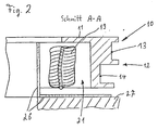
- FIG. 2 forms on the Holding device 10 or its ring 11 arranged, in particular molded, tires 12 with the ring 11 radially an L-profile on the inside.
- This L-profile limits together with a complementary, fixed relative to the headlight arranged L-profile 26, the circumferential channel 21.
- the L-profile 26 extends over a circumferential angle that is the maximum Angle of rotation of the holding device 10 corresponds, for example over a circumferential angle of at least 180 ° to 270 °.
- the complementary L-profile is the correspondingly long and peripheral channel 21 essentially closed on all sides formed for receiving the feed cable 19.
- Fig. 2 is also a piece of one designed as a front plate 27 Fastener to recognize that with the The headlight is connected and the aperture angle is like an aperture of the headlight defined.
- the L-profile 26 is attached to the front panel 27.
- the front panel 27 can either a component of the headlight, a separate one Component or part of the facility.
- the pinion 17 is also rotatably mounted on the front plate 27 and in this way, as well as that associated with the pinion 17 Drive, mounted on the front plate 27.
- the mirror images form those facing each other L profiles essentially closed on all sides Channel with rectangular or square Cross-section.
- the feed cable 19, which is designed as a flat cable is kept secure within this channel. Besides, will sufficient radial space for the formation of the mentioned Reverse loop 24 created.
- the axial distance of the rotatably mounted holding device 10 from the front plate 27 is through the mentioned bearing rollers 15th guaranteed due to their placement in the in FIG upper circumferential groove 13.
- bearing rollers 15 can also be that of FIG. 2 be assigned to the lower circumferential groove 14. Then the Inclusion of the drive chain 16 within the upper circumferential groove 13.
- a defined guidance of the supply cable closed by a cross section framed channel guaranteed.
- the channel prevented in particular evading the reverse loop to the outside and the associated disruptive effect mentioned at the beginning.
- the holding device 30 shown in FIG. 4 is for holding one electrically operated device can be used to influence of light from a headlight with the headlight is connectable.
- the octagonal ring 48 on Light emission of the headlights attached that he the one Light has a dimming effect all around.
- the octagonal Ring 48 is part of the fastener 31 or is with the fastener 31 when mounting the holding device 30 connectable.
- Four eight are shown uniformly in FIG Screw connections distributed over the octagonal ring 48 49 to an annular plate of the fastener 31.
- the electrically operated part can in particular be a Anti-glare flap that is opened by an electric motor or can be closed.
- the electrically powered part is connected to the rotating ring 32.
- the rotating ring 32 surrounds one in a central potential Light propagation direction 28 rotating axis 20 all around in Distance. It is about the axis of rotation 20 relative to the fastener 31 rotatably mounted.
- the holding device has 30 an annular ring (not shown) between the fastening element 31 and the rotary ring 32 arranged rotary bearing, preferably a ball bearing.
- a rotary movement can, for example, that described with reference to FIGS. 1 and 3 Drive arrangement can be used.
- a flat cable 39 supply cable from a connector 43 on the outer periphery of the fastener 31 along via a cable deflection roller 33 on which the flat cable 39 is deflected approximately in the reverse direction up to electrically operated part of the facility.
- the flat cable 39 ends at a rotary stop 47 in the right half of the picture.
- the flat cable 39 fixed relative in another way to the rotating element 32 or to the electrically operated part to position the facility.
- the third cable section 42 is under tension in a continuous range of rotational positions.
- the tension is applied by a transmission element 36 formed from a pull cord 37 and a helical spring 38.
- the third cable section 42 also exerts a tensile force on the transmission element 36 which causes a tension of the transmission element 36.
- the transmission element 36 is connected at its first end to the outer circumference of the fastening element 31. At its second end 45 it is connected to a rotary stop 47 which can be seen in FIGS. 4 and 5 in the left half of the figure.
- the helical spring 38 connects the rotary stop 47 to the end of the pull cord 37.
- the cable deflection roller 33 has a central, axial bore or recess in which a shaft 53 is arranged.
- the shaft 53 is at its ends each provided with an external thread, one on each Nut 52 is screwed on. One end protrudes a hole in a connecting plate 46 through to the side of the connecting plate facing away from the cable deflection roller 33 46.
- the drawstring pulley 34 connected to the connecting plate 46.
- the cable deflection roller 33 has a profile rectangular groove 50 for receiving the flat cable 39.
- the Drawstring pulley 34 has a conical profile tapering groove 51 for receiving the pull cord 37.
- the groove-like tread 35 only a small groove profile depth, d. H. the supernatant of the two Walls laterally on the tread 35 in the radial direction to the outside is small.
- the device according to the invention in particular by the is particularly preferred embodiment described above reliable routing of a supply cable within of a defined spatial area over a continuous range of rotational positions of the device guaranteed. Due to the special construction of the Holding device of the device is handling, especially the assembly and maintenance, compared to the facility already known facilities simplified.
Landscapes
- Engineering & Computer Science (AREA)
- General Engineering & Computer Science (AREA)
- Physics & Mathematics (AREA)
- Spectroscopy & Molecular Physics (AREA)
- Lighting Device Outwards From Vehicle And Optical Signal (AREA)
- Non-Portable Lighting Devices Or Systems Thereof (AREA)
- Storing, Repeated Paying-Out, And Re-Storing Of Elongated Articles (AREA)
- Circuit Arrangements For Discharge Lamps (AREA)
Abstract
Description
Die Erfindung betrifft eine elektrisch betriebene Einrichtung, insbesondere eine elektromotorisch angetriebene Einrichtung, wie Farbwechsler, Abblendklappe, Lichtjalousie oder dergleichen, für einen Scheinwerfer, insbesondere für einen Bühnenscheinwerfer.The invention relates to an electrically operated device, in particular an electric motor-driven device, such as color changer, anti-dazzle flap, light blind or the like, for a spotlight, especially for a stage spotlight.
Die Einrichtung dient der Beeinflussung von Licht aus dem Scheinwerfer. Sie weist eine Haltevorrichtung auf, die zum Halten der Einrichtung über ein, vorzugsweise ringartiges, Befestigungselement mit dem Scheinwerfer verbindbar ist und die ein, vorzugsweise ringartiges, Drehelement aufweist, das um eine in eine potentielle Lichtausbreitungsrichtung verlaufende Drehachse relativ zu dem Befestigungselement drehbar ist. Das Befestigungselement und/oder das Drehelement umfangen die Drehachse zumindest teilweise mit Abstand.The device serves to influence light from the Headlights. It has a holding device for holding the device via a, preferably ring-like, fastening element is connectable to the headlight and the has a, preferably ring-like, rotating element which around one that runs in a potential light propagation direction Axis of rotation is rotatable relative to the fastener. The Fastening element and / or the rotary element encompass the Axis of rotation at least partially at a distance.
Einrichtungen der vorgenannten Art sind allgemein bekannt. Die Scheinwerfer sind vorzugsweise zwischen den beiden Schenkeln eines U-förmigen Traggestells um eine horizontale Achse schwenkbar gelagert. Das Traggestell selbst ist um eine vertikale Achse verschwenkbar gelagert. Damit läßt sich der Scheinwerfer praktisch auf jeden gewünschten Punkt ausrichten. Häufig ist es wünschenswert, die Haltevorrichtung der Einrichtung vor oder an dem Lichtaustritt des Scheinwerfers anzuordnen. Die Haltevorrichtung ist in der Regel drehbar gelagert, und zwar um eine in eine potentielle Lichtausbreitungsrichtung verlaufende Drehachse. Sofern die Einrichtung elektrisch betrieben wird, ist es erforderlich, eine elektrische Verbindung, vorzugsweise zwischen der Einrichtung an der drehbar gelagerten Haltevorrichtung und dem stationären Scheinwerfer herzustellen. Herkömmlich erfolgt diese elektrische Verbindung durch ein frei durchhängendes Zuführungskabel, welches die Drehbewegungen der Haltevorrichtung relativ zum Scheinwerfer erlaubt. Das Zuführungskabel muß eine dem Drehbereich entsprechende Länge haben. Aufgrund dieser Länge kann das Zuführungskabel störend wirken, insbesondere dann, wenn der Scheinwerfer dicht über dem Boden angeordnet ist. Es besteht dann die Gefahr, daß Personen, insbesondere Bühnenarbeiter, am Zuführungskabel hängenbleiben, oder daß bei der Montage des Scheinwerfers der freihängende Teil des Zuführungskabels beschädigt wird.Devices of the aforementioned type are generally known. The Headlights are preferably between the two legs a U-shaped support frame around a horizontal axis pivoted. The support frame itself is vertical Axially pivoted. So that the headlight Align practically to any desired point. Often it is desirable to provide the holding device to the device or to be arranged at the light outlet of the headlight. The Holding device is usually rotatably mounted, namely one that runs in a potential light propagation direction Axis of rotation. If the device is operated electrically, it is necessary to make an electrical connection, preferably between the device on the rotatably mounted holding device and to manufacture the stationary headlight. Traditionally this electrical connection is made by a free sagging supply cable, which the rotation of the Holding device allowed relative to the headlight. The feed cable must have a length corresponding to the range of rotation. Because of this length, the feed cable can be annoying act, especially when the headlight is close above the Floor is arranged. There is then a risk that people especially stage workers, get stuck on the supply cable, or that when mounting the headlight the free hanging Part of the supply cable is damaged.
Aufgabe der vorliegenden Erfindung ist es, eine elektrisch betriebene, insbesondere eine elektromotorisch angetriebene, Einrichtung zum Beeinflussen von Licht aus einem Scheinwerfer, insbesondere aus einem Bühnenscheinwerfer, der eingangs genannten Art anzugeben, bei der ein Zuführungskabel möglichst nach außen strörungsfrei und platzsparend angeordnet ist.The object of the present invention is an electrical operated, in particular an electric motor driven, Device for influencing light from a headlight, especially from a stage spotlight at the beginning Specify the type mentioned, where possible with a supply cable is arranged outside in a trouble-free and space-saving manner.
Diese Aufgabe wird durch eine Einrichtung mit den Merkmalen des Anspruchs 1 gelöst. Weiterbildungen sind Gegenstand der abhängigen Ansprüche.This task is carried out by a facility with the characteristics of Claim 1 solved. Further training is the subject of dependent claims.
Die erfindungsgemäße Einrichtung für einen Scheinwerfer weist eine Haltevorrichtung auf, die zum Halten der Einrichtung über ein, vorzugsweise ringartiges, Befestigungselement mit dem Scheinwerfer verbindbar ist und die ein, vorzugsweise ringartiges, Drehelement aufweist, das um eine in eine potentielle Lichtausbreitungsrichtung verlaufende Drehachse relativ zu dem Befestigungselement drehbar ist. Das Befestigungselement und/oder das Drehelement umfangen die Drehachse zumindest teilweise mit Abstand. Ein elektrisches Zuführungskabel für die Einrichtung ist an einem ersten Kabelabschnitt ortsfest relativ zu dem Befestigungselement und an einem zweiten Kabelabschnitt ortsfest relativ zu dem Drehelement positionierbar bzw. positioniert. Ein etwa in Umfangsrichtung verlaufender dritter Kabelabschnitt, der im Verlauf des Kabels zwischen dem ersten Kabelabschnitt und dem zweiten Kabelabschnitt liegt, führt derart zumindest an einer Kabelstelle unter Ausbildung einer Umkehrschleife etwa in Umkehrrichtung zurück, daß sich bei Drehung der Haltevorrichtung die Position der Umkehrschleife relativ zu dem ersten und zu dem zweiten Kabelabschnitt ändert.The device according to the invention for a headlight has a holding device which is used to hold the device a, preferably ring-like, fastener with the Headlight is connectable and the one, preferably ring-like, Has rotary element, which in one potential Direction of light propagation axis of rotation relative to the Fastener is rotatable. The fastener and / or the rotary element at least partially encompass the axis of rotation with distance. An electrical supply cable for the The device is fixed relative to a first cable section to the fastener and to a second cable section stationary relative to the rotating element. A third running approximately in the circumferential direction Section of cable that runs in the course of the cable between the first Cable section and the second cable section lies leads such at least at a cable point with the formation of a Reverse loop back in the reverse direction that at Rotation of the holding device the position of the reversing loop changes relative to the first and second cable sections.
Der Kern der Erfindung liegt also darin, das etwa in Umfangsrichtung verlaufende elektrische Zuführungskabel unter Ausbildung einer Umkehrschleife zurückzuführen, so daß, unter Veränderung der relativen Position der Umkehrschleife zu den ortsfesten Kabelstellen am Befestigungselement bzw. Scheinwerfer und am Drehelement, das Drehelement gegen das Befestigungselement verdrehbar ist. Damit kann sich das Kabel in jeder Drehstellung in Umfangsrichtung hin- und zurückerstrecken. Es muß daher insbesondere nicht von der Einrichtung bzw. vom Scheinwerfer störend herunterhängen, um eine Verdrehung zu ermöglichen.The essence of the invention therefore lies in the fact that in Electrical supply cable running under circumferential direction Formation of a reverse loop attributed so that, under Change the relative position of the reverse loop to the stationary cable points on the fastening element or Headlights and on the rotating element, the rotating element against that Fastener is rotatable. So that the cable can back and forth in every rotational position in the circumferential direction stretch back. In particular, it does not have to be from Hanging device or hanging from the headlight to to allow twisting.
Die vorgegebene Umkehrschleife verhindert weiterhin eine Stauchungsgefahr des Kabels, da sich die Umkehrschleife je nach Drehbewegung der Haltevorrichtung mit dieser mitbewegt. Insbesondere kann eine Festklemmung des Kabels am stationären Bühnenscheinwerfer einerseits und an der drehbeweglich gelagerten Haltevorrichtung andererseits so erfolgen, daß die festgeklemmten Enden jeweils in dieselbe Umfangsrichtung weisen.The predetermined reverse loop continues to prevent one Danger of compression of the cable, since the reversing loop varies depending on Rotational movement of the holding device moves with it. In particular, the cable can be clamped on the stationary Stage lights on the one hand and on the rotating stored holding device on the other hand so that the clamped ends in the same circumferential direction point.
Bei einer Ausgestaltung der Erfindung ist das Zuführungskabel, das dann vorzugsweise als Flachkabel ausgebildet ist, zwischen dem stationären Bühnenscheinwerfer und der drehbeweglich gelagerten Haltevorrichtung so angeordnet, daß es von außen her weder zugänglich noch sichtbar ist. Die Anordnung des Kabels erfolgt innerhalb eines Umfangskanals bzw. Kanalabschnitts im Bereich der Drehlagerung zwischen Bühnenscheinwerfer und Haltevorrichtung. In one embodiment of the invention, the feed cable is which is then preferably designed as a flat cable between the stationary stage spotlight and the rotating one mounted holding device arranged so that it from the outside is neither accessible nor visible. The arrangement of the cable takes place within a circumferential channel or channel section in Area of the pivot bearing between stage lights and Holding device.
Vorzugsweise ist der dritte Kabelabschnitt, der im Verlauf des Kabels zwischen dem ersten und dem zweiten Kabelabschnitt liegt, durch ein Umlenkelement etwa in Umkehrrichtung umgelenkt bzw. umlenkbar, wobei das Umlenkelement entlang einer Führung an einem Außenumfang des Drehelementes und/oder des Befestigungselementes derart bewegbar ist, daß in einem kontinuierlichen Bereich von Drehstellungen der dritte Kabelabschnitt unter Zugspannung steht.Preferably, the third cable section, which is in the course of Cable between the first and the second cable section is deflected by a deflecting element approximately in the reverse direction or deflectable, the deflecting element along a guide on an outer circumference of the rotating element and / or the fastening element is so movable that in a continuous Range of rotational positions of the third section of cable is under tension.
Aufgrund des geführten Umlenkelementes ist eine kanalartig geschlossene Führung nicht erforderlich, wenn auch möglich. Somit kann die Führung derart ausgeführt werden, daß der bewegbare dritte Kabelabschnitt leicht zugänglich ist, so daß das Zuführungskabel beispielsweise einfach ausgewechselt werden kann oder erst nach dem Anbringen der Haltevorrichtung an dem Scheinwerfer montiert werden kann. Aufgrund der Zugspannung, unter der der dritte Kabelabschnitt steht, ist sichergestellt, daß der dritte Kabelabschnitt keine unerwünschten Schlaufen bildet und sich daher an Teilen der Einrichtung verklemmt oder verhakt. Insbesondere ist es möglich, alle Kabelarten zu verwenden, wobei jedoch ein in dem dritten Kabelabschnitt reversibel biegbares Kabel zu verwenden ist.Because of the guided deflection element, a channel-like one is closed Guided tour not necessary, if possible. Consequently can be carried out such that the movable third cable section is easily accessible, so that Feed cables can be easily replaced, for example can or only after attaching the holding device to the Headlights can be mounted. Because of the tension, under which the third cable section is located, is ensured that the third cable section has no unwanted loops forms and therefore jammed on parts of the device or hooked. In particular, it is possible to use all types of cables however, one in the third cable section is reversible bendable cable is to be used.
Bei einer Weiterbildung der Einrichtung weist die Haltevorrichtung ein längliches, zumindest in einem Abschnitt reversibel biegbares Übertragungselement zum Übertragen einer Zugkraft auf den dritten Kabelabschnitt auf. Das Befestigungselement ist mit einem ersten Ende des Übertragungselementes verbunden. Das Übertragungselement erstreckt sich ungefähr in Umfangsrichtung an dem Außenumfang des Drehelementes und/oder des Befestigungselementes, ist durch ein entlang der Führung bewegbares Umlenkelement etwa in Umkehrrichtung umgelenkt und ist an einem zweiten Ende mit dem Drehelement verbunden. Auf diese Weise ist die Zugspannung auf den dritten Kabelabschnitt besonders einfach aufzubringen. Das Übertragungselement und der dritte Kabelabschnitt können in unterschiedlichen räumlichen Bereichen an dem Außenumfang verlaufen, so daß eine störende Reibung des Übertragungselementes an dem dritten Kabelabschnitt ausgeschlossen ist.In a development of the device, the holding device an elongated, at least in one section reversible bendable transmission element for transmitting a tensile force the third cable section. The fastener is with connected to a first end of the transmission element. The Transmission element extends approximately in the circumferential direction on the outer circumference of the rotating element and / or the fastening element, is by a deflecting element movable along the guide deflected approximately in the reverse direction and is on a second End connected to the rotating element. That way it is Tension on the third cable section is particularly easy to apply. The transmission element and the third cable section can be in different spatial areas on the Outer circumference run, so that a disturbing friction of the transmission element excluded on the third cable section is.
Vorzugsweise enthält das Übertragungselement ein elastisches Zugelement zum Aufbringen der Zugspannung. Besonders günstig ist es, wenn das Zugelement geringfügig beabstandet von dem Außenumfang an dem einen Ende des Übertragungselementes angeordnet ist, damit eine freie, ungestörte Längenänderung und damit die volle Funktionsfähigkeit des Zugelementes gewährleistet ist. Bevorzugtermaßen ist das Zugelement eine Schraubenfeder. Das Zugelement gleicht aufgrund seiner Elastizität Längenänderungen, beispielsweise plastische Dehnungen, des Übertragungselementes und des Zuführungskabels aus. Eine Schraubenfeder ist dabei besonders vorteilhaft, da sie kostengünstig beschafft werden kann und relativ zu ihrer Länge im entspannten Zustand eine große reversible Längenänderung zuläßt.The transmission element preferably contains an elastic element Tension element for applying tension. Very cheap it is when the pulling element is slightly spaced from the outer circumference arranged at one end of the transmission element is for a free, undisturbed change in length and thus ensuring the full functionality of the tension element is. The tension element is preferably one Coil spring. The tension element is the same due to its Elasticity changes in length, for example plastic Strains, the transmission element and the feed cable out. A coil spring is particularly advantageous because it can be obtained inexpensively and relative to yours Length in the relaxed state a large reversible Allows length change.
Bei einer Weiterbildung weist das Drehelement einen Drehanschlag auf, mit dem das zweite Ende des Übertragungselementes verbunden ist. Der Drehanschlag erfüllt somit zwei Funktionen. Vorzugsweise ist der Drehanschlag im Abstand zu dem Außenumfang des Befestigungselementes angeordnet, an dem die Führung für das Umlenkelement ausgebildet ist. Der Drehanschlag liegt dabei in radialer Richtung weiter entfernt von der Drehachse als der Außenumfang. Ein Vorteil dieser Ausgestaltung ist eine gute Zugänglichkeit des Übertragungselementes und damit eine Montagefreundlichkeit bei gleichzeitiger Sicherstellung der ungehinderten Verdrehbarkeit der Haltevorrichtung.In one development, the rotary element has a rotary stop with which the second end of the transmission element connected is. The rotary stop therefore fulfills two functions. The rotary stop is preferably at a distance from the outer circumference arranged of the fastener on which the guide for the deflection element is formed. The rotation stop is there in the radial direction further away from the axis of rotation than that Outer circumference. An advantage of this configuration is good accessibility of the transmission element and thus ease of installation while ensuring the unhindered The holding device can be rotated.
Das Umlenkelement zum Umlenken des Zuführungskabels und das Umlenkelement zum Umlenken des Übertragungselementes können ein und dasselbe Bauteil sein. Bevorzugt wird jedoch, daß das Umlenkelement zum Umlenken des Zuführungskabels ein erstes Umlenkelement ist, daß das Umlenkelement zum Umlenken des Übertragungselementes ein zweites Umlenkelement ist und daß die beiden Umlenkelemente in Umfangrichtung hintereinander und in einer festen Position relativ zueinander angeordnet sind. Durch die Verteilung der Umlenkfunktionen auf zwei Umlenkelemente wird eine leichtere Handhabbarkeit und eine leichtere Anpassung an die Eigenschaften, z. B. Abmessungen, Reibungskoeffizienten oder Biegefähigkeit, der umzulenkenden Teile ermöglicht.The deflecting element for deflecting the feed cable and the deflecting element to redirect the transmission element can and be the same component. However, it is preferred that the deflecting element a first deflecting element for deflecting the feed cable is that the deflecting element for deflecting the transmission element is a second deflecting element and that the two deflection elements in the circumferential direction one behind the other and in are arranged in a fixed position relative to each other. By the distribution of the diverting functions over two diverting elements becomes easier to handle and easier to adjust to the properties, e.g. B. dimensions, coefficient of friction or the ability to bend the parts to be deflected.
Bevorzugt wird eine Weiterbildung, bei der das Umlenkelement bzw. mindestens eines der Umlenkelemente eine Umlenkrolle mit einer Nut zur Führung des Zuführungskabels bzw. des Übertragungselementes ist. Das Zuführungskabel bzw. das Übertragungselement kann entweder schlupffrei an der Nut abrollen, mit Schlupf abrollen oder lediglich in der Nut geführt abgleiten, wenn die Haltevorrichtung eine Drehbewegung ausführt. Ist ein Schlupf zu erwarten, wird für die Umlenkrolle ein Material bevorzugt, insbesondere ein Lagerwerkstoff, mit dem sich besonders reibungsarme Oberflächen herstellen lassen. Geringe Reibung verhindert zum einen Verschleiß und zum anderen eine nennenswerte Geräuschentwicklung. Bevorzugt wird, daß die mindestens eine Umlenkrolle so, vorzugsweise auf einer Welle, drehbar gelagert ist, daß sie bei Verdrehung des Drehelementes an der Führung abrollt. Für diese Abrollbewegung gilt das zuvor gesagte entsprechend.A further development is preferred in which the deflecting element or at least one of the deflection elements with a deflection roller a groove for guiding the supply cable or the transmission element is. The supply cable or the transmission element can either roll on the groove without slipping, with Unroll slip or just slide in the groove, when the holding device rotates. Is a Expected slippage, a material is preferred for the guide roller, in particular a bearing material with which special Have low-friction surfaces produced. Low friction prevents wear and tear on the one hand significant noise development. It is preferred that the at least one deflection roller like this, preferably on a shaft, is rotatably mounted so that when the rotating element is rotated rolls on the guide. This previously applies to this rolling motion said accordingly.
Günstig ist es, wenn das Drehelement an seinem Außenumfang eine in Umfangsrichtung verlaufende, nutartig seitlich bewandete Lauffläche hat, die die Führung für das Umlenkelement bzw. die Umlenkelemente ist. Die Lauffläche ist vorzugsweise eine geglättete, insbesondere polierte, Metalloberfläche. Alternativ zu dieser Ausgestaltung befindet sich in der Lauffläche eine in Umfangsrichtung verlaufende Vertiefung, durch die das Umlenkelement seitlich geführt ist. Bei der zuerst genannten Alternative ist die Herstellung besonders einfach, da beispielsweise die Lauffläche durch den Außenumfang einer kreisringförmigen Platte gebildet ist, an der zur seitlichen Bewandung der Lauffläche koaxial zwei dünnere ebenfalls kreisringförmige Platten mit größerem Außenradius montiert sind.It is favorable if the rotary element has a on its outer circumference in the circumferential direction, laterally walled groove-like Has tread that the guide for the deflecting element or Deflection elements is. The tread is preferably a smooth, especially polished, metal surface. Alternatively for this configuration there is an in in the tread Recess extending circumference through which the deflecting element is guided laterally. In the first alternative the production is particularly simple because, for example the tread through the outer circumference of an annular Plate is formed on the side wall of the tread coaxial two thinner, also circular plates with a larger outer radius.
Die erfindungsgemäße Einrichtung erlaubt prinzipiell die Verwendung von Zuführungskabeln mit beliebigen Querschnitten. Bevorzugt wird jedoch ein Zuführungskabel, das als Flachkabel ausgebildet ist und das so angeordnet oder anordenbar ist, daß sich in dem dritten Kabelabschnitt eine flache Seite ungefähr entlang der Führung, insbesondere der Lauffläche, erstreckt. Bei geeigneter Ausführung des Umlenkelementes, z. B. bei Verwendung einer Umlenkrolle, unterstützt ein derart angeordnetes oder anordenbares Flachkabel die Führung bei der Ausübung ihrer Funktion.In principle, the device according to the invention permits use of supply cables with any cross-section. Prefers however, becomes a feed cable that is called a flat cable is formed and which is arranged or can be arranged so that a flat side approximately in the third cable section extends along the guide, in particular the tread. With a suitable design of the deflecting element, for. B. in use a deflection roller, supports one arranged in this way or arrangable flat cable to guide you in the exercise of your Function.
Die Erfindung wird im folgenden anhand der beigefügten Zeichnung beispielhaft näher erläutert. Sie ist jedoch nicht auf die in der Zeichnung gezeigten Ausführungsbeispiele beschränkt. Die einzelnen Figuren der Zeichnung zeigen:
- Fig. 1
- den wesentlichen Teil einer an dem Lichtaustritt eines nicht näher dargestellten Scheinwerfers drehbar gelagerten Haltevorrichtung in schematischer Draufsicht,
- Fig. 2
- die Konstruktion gemäß Fig. 1 im Schnitt längs der Linie A-A in Fig. 1 und
- Fig. 3
- die Haltevorrichtung gemäß Fig. 1 in einer gegenüber Fig. 1 geänderten Drehstellung.
- Fig. 4
- eine perspektivische Darstellung einer Haltevorrichtung eines zweiten Ausführungsbeispiels der Erfindung,
- Fig. 5
- eine weitere perspektivische Darstellung der Haltevorrichtung in Teilansicht und
- Fig. 6
- eine Seitenansicht zweier miteinander verbundener Umlenkrollen der Haltevorrichtung gemäß Fig. 4 und 5.
- Fig. 1
- the essential part of a holding device rotatably mounted on the light exit of a headlight, not shown, in a schematic plan view,
- Fig. 2
- the section of FIG. 1 in section along the line AA in Fig. 1 and
- Fig. 3
- 1 in a changed rotational position compared to FIG. 1.
- Fig. 4
- 2 shows a perspective illustration of a holding device of a second exemplary embodiment of the invention,
- Fig. 5
- a further perspective view of the holding device in partial view and
- Fig. 6
- a side view of two interconnected pulleys of the holding device according to FIGS. 4 and 5.
Eine erste Ausführungsform der Erfindung wird nun anhand von Fig. 1 bis Fig. 3 beschrieben. A first embodiment of the invention will now be described with reference to 1 to 3 are described.
Die Haltevorrichtung 10 zum Beeinflussen von Licht aus einem
nicht dargestellten Scheinwerfer dient dem Halten einer oder
mehrerer elektrisch betriebener Einrichtungen, wie Farbwechslern,
Abblendklappen, Lichtjalousien oder dergleichen, die
ebenfalls nicht dargestellt sind.The holding
Ein Grundelement der Haltevorrichtung 10 ist ein Ring 11, auf
den beispielsweise eine Montageplatte montierbar ist, die die
vorerwähnten Einrichtungen trägt und mit der diese Einrichtungen
um eine Drehachse 20 drehbar sind, die in Fig. 1 und Fig. 3
senkrecht auf der Bildebene steht. An der dem Scheinwerfer zugewandten
Seite des Rings 11 ist ein umlaufender Reifen 12 angeordnet,
der radial außenseitig ein E-förmiges Profil aufweist,
wobei die eine so gebildete Umfangsnut 13 zur Aufnahme
von wenigstens drei gleichmäßig über den Umfang des
Lichtaustritts des Scheinwerfers verteilt angeordneten, jeweils
drehbar gelagerten, insbesondere kugel- oder nadelgelagerten,
Lagerrollen 15 dient. Die andere Umfangsnut 14 dient der
Aufnahme einer Antriebskette 16 oder alternativ eines Antriebsriemens,
wobei die Antriebskette 16 mit einem Ritzel 17 eines
am Scheinwerfers montierten Elektromotors, insbesondere eines
Schritt- oder Getriebemotors, gekoppelt ist. Damit die Mitnahme
des Rings 11 und damit des drehbaren Teils der Haltevorrichtung
10, durch die Antriebskette 16 sichergestellt ist, ist diese an
wenigstens einem Punkt mit dem Ring 11 bzw. mit dem mit diesem
verbundenen Reifen 12 verbunden. Gleichzeitig bewirkt diese Fixierung
der Kette eine Drehwinkelbegrenzung für die Haltevorrichtung
10.A basic element of the holding
Die Haltevorrichtung 10 sowie die in den Fig. 1 bis Fig. 3
nicht dargestellte Montageplatte weisen eine zentrale Durchgangsöffnung
18 für das Licht aus dem Scheinwerfer auf, so daß
die Haltevorrichtung 10 die Drehachse 20 vollständig mit Abstand
umfängt. Insbesondere begrenzt die Haltevorrichtung 10
den Lichtaustritt des Scheinwerfers umfangsmäßig aufgrund ihrer
Anordnung vor dem Lichtaustritt des Scheinwerfers. The holding
Die elektrische Verbindung zu dem drehbaren Teil der elektrisch
betriebenen Einrichtung ist durch ein Zuführungskabel 19 hergestellt,
das als Flachkabel ausgeführt ist. Ein Abschnitt des
Zuführungskabels 19 erstreckt sich innerhalb eines durch die
Haltevorrichtung 10 ausgebildeten Umfangskanals 21, wobei eine
flache Seite der Drehachse 20 zugewandt ist. Jeweils ein weiterer
Kabelabschnitt, insbesondere ein Ende, ist ortsfest relativ
zu dem Bühnenscheinwerfer, bzw. zu einem mit dem
Bühnenscheinwerfer verbundenen Befestigungselement, und zu dem
drehbaren Teil der Haltevorrichtung 10 positioniert,
insbesondere festgeklemmt. Die Drehachse der Haltevorrichtung
ist in den Figuren 1 und 3 mit der Bezugsziffer 20
gekennzeichnet. Diese Drehachse fluchtet vorzugsweise mit der
optischen Achse des Bühnenscheinwerfers.The electrical connection to the rotatable part of the electrical
operated device is manufactured by a
Innerhalb des Umfangskanals 21 ist das Zuführungskabel 19 unter
Ausbildung einer Umkehrschleife 24 plaziert, so daß es ohne
Gefahr einer Stauchung bei Drehung der Haltevorrichtung 10
innerhalb des Umfangskanals bewegt wird. Die Umkehrschleife 24
verändert dabei ihre Position innerhalb des Umfangskanals 21,
und zwar jeweils etwa um die Hälfte des Drehwinkels der
Haltevorrichtung 10.Within the
Wie aus Fig. 2 erkennbar ist, bildet der an der
Haltevorrichtung 10 bzw. dessen Ring 11 angeordnete,
insbesondere angeformte, Reifen 12 mit dem Ring 11 radial
innenseitig ein L-Profil. Dieses L-Profil begrenzt zusammen mit
einem komplementären, relativ zu dem Scheinwerfer ortsfest
angeordneten L-Profil 26 den Umfangskanal 21. Das L-Profil 26
erstreckt sich über einen Umfangswinkel, der dem maximalen
Drehwinkel der Haltevorrichtung 10 entspricht, beispielsweise
über einen Umfangswinkel von wenigstens 180° bis 270°. Durch
die komplementären L-Profile ist der entsprechend lange und
nach allen Seiten im wesentlichen geschlossene Umfangskanal 21
für die Aufnahme des Zuführungskabels 19 gebildet.As can be seen from Fig. 2, forms on the
In Fig. 2 ist außerdem ein Stück eines als Frontplatte 27 ausgebildeten
Befestigungselementes zu erkennen, das mit dem
Scheinwerfer verbunden ist und blendenartig den Lichtausbreitungswinkel
des Scheinwerferlichts definiert. Das L-Profil 26
ist an der Frontplatte 27 befestigt. Die Frontplatte 27 kann
entweder ein Bestandteil des Scheinwerfers, ein separates
Bauteil oder ein Bestandteil der Einrichtung sein. Vorzugsweise
ist an der Frontplatte 27 auch das Ritzel 17 drehbar gelagert
und auf diese Weise, ebenso wie der dem Ritzel 17 zugeordnete
Antrieb, an der Frontplatte 27 montiert.In Fig. 2 is also a piece of one designed as a
Wie Figur 2 zeigt, bilden die spiegelbildlich einander zugekehrten
L-Profile einen im wesentlichen allseitig geschlossenen
Kanal mit rechteckförmigem oder quadratischem
Querschnitt. Das als Flachkabel audgeführte Zuführungskabel 19
ist innerhalb dieses Kanals sicher gehalten. Außerdem wird
ausreichend radialer Raum für die Ausbildung der erwähnten
Umkehrschleife 24 geschaffen.As FIG. 2 shows, the mirror images form those facing each other
L profiles essentially closed on all sides
Channel with rectangular or square
Cross-section. The
Der axiale Abstand der drehbar gelagerten Haltevorrichtung 10
von der Frontplatte 27 wird durch die erwähnten Lagerrollen 15
gewährleistet, aufgrund ihrer Plazierung in der in Figur 2
oberen Umfangsnut 13.The axial distance of the rotatably mounted holding
Alternativ können die Lagerrollen 15 auch der in Figur 2
unteren Umfangsnut 14 zugeordnet sein. Dann erfolgt die
Aufnahme der Antriebskette 16 innerhalb der oberen Umfangsnut
13.Alternatively, the bearing
Es sei auch noch darauf hingewiesen, daß an den Festklemmpunkten
22, 23 des Flachkabels 19 dieses jeweils umgefaltet ist
derart, daß die Endabschnitte des Flachkabels sich in einem
Winkel von 90° gegenüber dem Flachkabel innerhalb der Ebene
desselben erstrecken.It should also be noted that at the clamping points
22, 23 of the
Bei der beschriebenen Ausführungsform wird eine definierte Führung des Zuführungskabels durch einen im Querschnitt geschlossen umrandeten Kanal gewährleistet. Der Kanal verhindert insbesondere ein Ausweichen der Umkehrschlaufe nach außen und die damit verbundene, eingangs erwähnte störende Wirkung. In the described embodiment, a defined guidance of the supply cable closed by a cross section framed channel guaranteed. The channel prevented in particular evading the reverse loop to the outside and the associated disruptive effect mentioned at the beginning.
Nun wird anhand der Fig. 4 bis 6 eine zweite, besonders bevorzugte Ausführungsform der Erfindung beschrieben. Sämtliche im Zusammenhang mit der ersten Ausführungsform offenbarten Merkmale kommen aber einzeln oder zu mehreren für eine Kombination mit Merkmalen der zweiten Ausführungsform in Betracht, soweit eine solche Kombination sinnvoll ist. Beispielsweise kann die unten beschriebene Anordnung von Umlenkrollen in einem geschlossen umrandeten Kanal nach Fig. 2 angeordnet sein.4 to 6, a second one, especially described preferred embodiment of the invention. All disclosed in connection with the first embodiment Characteristics come individually or in groups for one Combination with features of the second embodiment in Consider if such a combination makes sense. For example, the arrangement of Deflection rollers in a closed-edged channel according to FIG. 2 be arranged.
Bei der zweiten Ausführungsform ist eine definierte Führung für einen beweglichen Abschnitt eines Zuführungskabels vorhanden, wobei der bewegliche Abschnitt gut zugänglich ist.In the second embodiment, a defined guide for there is a movable section of a feed cable, the movable section being easily accessible.
Die in Fig. 4 gezeigte Haltevorrichtung 30 ist zum Halten einer
elektrisch betriebenen Einrichtung einsetzbar, die zum Beeinflussen
von Licht aus einem Scheinwerfer mit dem Scheinwerfer
verbindbar ist. Hierzu wird der achteckige Ring 48 so am
Lichtaustritt des Scheinwerfers befestigt, daß er eine das
Licht seitlich rundherum abblendende Wirkung hat. Der 8-eckige
Ring 48 ist Bestandteil des Befestigungselementes 31 oder ist
mit dem Befestigungselement 31 bei der Montage der Haltevorrichtung
30 verbindbar. Gezeigt sind in Fig. 4 acht gleichmäßig
über den 8-eckigen Ring 48 verteilt angeordnete Schraubverbindungen
49 zu einer ringförmigen Platte des Befestigungselementes
31. An der Unterseite der Haltevorrichtung
30, die in montiertem Zustand die von dem Scheinwerfer abgewandte
Seite der Haltevorrichtung 30 bildet, ist der elektrisch
betriebene, hier nicht dargestellte, Teil der Einrichtung montiert.
Der elektrisch betriebene Teil kann insbesondere eine
Abblendklappe sein, die elektromotorisch angetrieben geöffnet
oder geschlossen werden kann. Der elektrisch betriebene Teil
ist mit dem Drehring 32 verbunden.The holding
Der Drehring 32 umfängt eine in eine zentrale potentielle
Lichtausbreitungsrichtung 28 verlaufende Drehachse 20 rundum in
Abstand. Er ist um die Drehachse 20 relativ zu dem Befestigungselement
31 drehbar gelagert. Hierzu weist die Haltevorrichtung
30 ein nicht gezeigtes ringförmig zwischen dem Befestigungselement
31 und dem Drehring 32 angeordnetes Drehlager,
vorzugsweise ein Kugellager, auf. Zum Antrieb einer Drehbewegung
kann beispielsweise die anhand von Fig. 1 und Fig. 3 beschriebene
Antriebsanordnung verwendet werden.The rotating
Für den elektrisch betriebenen Teil der Einrichtung führt ein
als Flachkabel 39 ausgeführtes Zuführungskabel von einem Anschlußstecker
43 an dem Außenumfang des Befestigungselementes
31 entlang über eine Kabel-Umlenkrolle 33, an der das Flachkabel
39 ungefähr in Umkehrrichtung umgelenkt wird, bis zu dem
elektrisch betriebenen Teil der Einrichtung. In der Darstellung
der Fig. 4 und Fig. 5 endet das Flachkabel 39 an einem Drehanschlag
47 in der rechten Bildhälfte. Bei vollständig montierter
Einrichtung kann an diesem Drehanschlag 47 beispielsweise eine
Zugentlastung für das Flachkabel 39 befestigt sein. Es ist aber
ebenso möglich, das Flachkabel 39 auf andere Weise fest relativ
zu dem Drehelement 32 bzw. zu dem elektrisch betriebenen Teil
der Einrichtung zu positionieren. In jedem Fall jedoch weist
das Zuführungskabel, hier das Flachkabel 39, einen ersten Kabelabschnitt
40, an dem es ortsfest relativ zu dem Befestigungselement
31 positioniert ist, einen zweiten Kabelabschnitt
41, an dem es ortsfest relativ zu dem Drehelement 32 positioniert
ist, und einen dritten Kabelabschnitt 42, der bei Drehbewegungen
der Haltevorrichtung sowohl relativ zu dem Befestigungselement
31 als auch relativ zu dem Drehring 32 bewegt
wird, auf.Introduces for the electrically powered part of the facility
as a
Der dritte Kabelabschnitt 42 steht in einem kontinuierlichen
Bereich von Drehstellungen unter Zugspannung. Die Zugspannung
wird durch ein aus einer Zugschnur 37 und einer Schraubenfeder
38 gebildetes Übertragungselement 36 aufgebracht. Umgekehrt übt
gemäß dem Newtonschen Axiom Actio gleich Reactio auch der
dritte Kabelabschnitt 42 eine eine Zugspannung des Übertragungselementes
36 bewirkende Zugkraft auf das Übertragungselement
36 aus. Das Übertragungselement 36 ist an seinem ersten
Ende am Außenumfang des Befestigungselementes 31 mit diesem
verbunden. An seinem zweiten Ende 45 ist es mit einem in Fig. 4
und Fig. 5 in der linken Bildhälfte erkennbaren Drehanschlag 47
verbunden. Dort verbindet die Schraubenfeder 38 den Drehanschlag
47 mit dem Ende der Zugschnur 37. Insbesondere bei Verwendung
einer Zugschnur 37, die nur geringfügig dehnbar ist,
ist somit eine wirksame und dennoch einfache Führung des
dritten Kabelabschnitts 42 sichergestellt. Wesentlich hierfür
ist auch die Lauffläche 35, an der das Flachkabel 39, das Übertragungselement
36 und die jeweilige Umlenkrolle 33; 34 in Umfangsrichtung
geführt sind. Im Unterschied zu der bereits bekannten,
eingangs beschriebenen Ausführungsform einer gattungsgemäßen
Einrichtung fehlt hier eine außenseitige Führung für
den dritten Kabelabschnitt 42. Die Funktion einer solchen
außenseitigen Führung wird durch die von dem Übertragungselement
36 und dem Flachkabel 39 gegenseitig aufeinander ausgeübten
Kräfte übernommen.The
Die Konstruktion der Umlenkrollen 33; 34 und ihre Verbindung
werden anhand von Fig. 6 beschrieben. Die Kabel-Umlenkrolle 33
weist eine zentrale, axiale Bohrung oder Ausnehmung auf, in der
eine Welle 53 angeordnet ist. Die Welle 53 ist an ihren Enden
jeweils mit einem Außengewinde versehen, auf das jeweils eine
Mutter 52 aufgeschraubt ist. Dabei ragt das eine Ende durch
eine Bohrung in einer Verbindungsplatte 46 hindurch bis zu der
von der Kabel-Umlenkrolle 33 abgewandten Seite der Verbindungsplatte
46. In ähnlicher Weise ist die Zugschnur-Umlenkrolle 34
mit der Verbindungsplatte 46 verbunden. Jedoch ist die rechte,
verdeckt gezeichnete Mutter 52 zur Montage der Kabel-Umlenkrolle
33 innerhalb einer in dieser ausgebildeten Ausnehmung
angeordnet. Die Kabel-Umlenkrolle 33 weist eine im Profil etwa
rechteckförmige Nut 50 zur Aufnahme des Flachkabels 39 auf. Die
Zugschnur-Umlenkrolle 34 weist dagegen eine im Profil konisch
zulaufende Nut 51 zur Aufnahme der Zugschnur 37 auf. Die durch
die Nut 51 definierte Laufebene für die Zugschnur 37 unterteilt
die Nut 50 in zwei etwa gleichgroße, zueinander symmetrische
Hälften, so daß eine einwandfreie zentrale Führung durch die
Zugschnur 37 an der Lauffläche 35 (Fig. 5) gegeben ist. Aus
diesem Grund weist die nutartig bewandete Lauffläche 35 nur
eine geringe Nutprofiltiefe auf, d. h. der Überstand der beiden
Wandungen seitlich an der Lauffläche 35 in radialer Richtung
nach außen ist gering.The construction of the
Durch die erfindungsgemäße Einrichtung, insbesondere durch die zuvor beschriebene besonders bevorzugte Ausführungsform ist eine zuverlässige Führung eines Zuführungskabels innerhalb eines definierten räumlichen Bereiches über einen kontinuierlichen Bereich von Drehstellungen der Einrichtung gewährleistet. Aufgrund der besonderen Konstruktion der Haltevorrichtung der Einrichtung ist die Handhabung, insbesondere die Montage und Wartung, der Einrichtung gegenüber bereits bekannten Einrichtungen vereinfacht. By the device according to the invention, in particular by the is particularly preferred embodiment described above reliable routing of a supply cable within of a defined spatial area over a continuous range of rotational positions of the device guaranteed. Due to the special construction of the Holding device of the device is handling, especially the assembly and maintenance, compared to the facility already known facilities simplified.
- 1010th
- HaltevorrichtungHolding device
- 1111
- Ringring
- 1212th
- Reifentires
- 1313
- UmfangsnutCircumferential groove
- 1414
- UmfangsnutCircumferential groove
- 1515
- LagerrolleStorage role
- 1616
- AntriebsketteDrive chain
- 1717th
- Ritzelpinion
- 1818th
- DurchgangsöffnungThrough opening
- 1919th
- ZuführungskabelSupply cable
- 2020th
- DrehachseAxis of rotation
- 2121
- UmfangskanalCircumferential channel
- 2222
- Kabel-Klemmstelle am ScheinwerferCable clamping point on the headlight
- 2323
- Kabel-Klemmstelle am DrehelementCable clamping point on the rotating element
- 2424th
- UmkehrschleifeReverse loop
- 2525th
- DrehrichtungDirection of rotation
- 2626
- L-ProfilL-profile
- 2727
- FrontplatteFront panel
- 2828
- zentrale potentielle Lichtausbreitungsrichtungcentral potential Direction of light propagation
- 3030th
- HaltevorrichtungHolding device
- 3131
- BefestigungselementFastener
- 3232
- DrehringRotating ring
- 3333
- Kabel-UmlenkrolleCable pulley
- 3434
- Zugschnur-UmlenkrolleDrawstring pulley
- 3535
- nutartig bewandete Laufflächegrooved tread
- 3636
- ÜbertragungselementTransmission element
- 3737
- ZugschnurPull cord
- 3838
- SchraubenfederCoil spring
- 3939
- FlachkabelFlat cable
- 4040
- erster Kabelabschnittfirst cable section
- 4141
- zweiter Kabelabschnittsecond section of cable
- 4242
- dritter Kabelabschnittthird section of cable
- 4343
- AnschlußsteckerConnector
- 4444
- erstes Ende first end
- 4545
- zweites Endesecond end
- 4646
- VerbindungsplatteConnecting plate
- 4747
- DrehanschlagRotary stop
- 4848
- 8-eckiger RingOctagonal ring
- 4949
- SchraubverbindungScrew connection
- 5050
- NutGroove
- 5151
- NutGroove
- 5252
- Muttermother
- 5353
- Wellewave
- 5454
- Wellewave
Claims (18)
dadurch gekennzeichnet, daß
ein elektrisches Zuführungskabel (19, 39) für die Einrichtung, das an einem ersten Kabelabschnitt (22, 40) ortsfest relativ zu dem Befestigungselement (31) und an einem zweiten Kabelabschnitt (23, 41) ortsfest relativ zu dem Drehelement (11, 12, 32) positioniert bzw. positionierbar ist, in einem etwa in Umfangsrichtung verlaufenden dritten Kabelabschnitt (42), der zwischen dem ersten (22, 40) und dem zweiten (23, 41) Kabelabschnitt unter Ausbildung einer Umkehrschleife (24) derart in Umkehrrichtung zurückführt, daß sich bei Drehung der Haltevorrichtung (10, 30) die Position der Umkehrschleife relativ zu dem ersten (22, 40) und relativ zu dem zweiten (23, 41) Kabelabschnitt ändert.Electrically operated device, in particular an electric motor-driven device, such as a color changer, dimming flap, light blind or the like, for influencing light from a spotlight, in particular from a stage spotlight, with a holding device (10, 30) which is used to hold the device via a, in particular ring-like fastening element (31) can be connected to the headlight and has a, in particular ring-like, rotating element (11, 12, 32) which is rotatable relative to the fastening element (31) about an axis of rotation (20) running in a potential light propagation direction (28), in particular driven by rotation, the fastening element (31) and / or the rotating element (11, 12, 32) extending at least partially at a distance around the axis of rotation (20),
characterized in that
an electrical supply cable (19, 39) for the device, which is stationary on a first cable section (22, 40) relative to the fastening element (31) and on a second cable section (23, 41) stationary relative to the rotating element (11, 12, 32) is positioned or can be positioned, in a third cable section (42) which runs approximately in the circumferential direction and which leads back in the reverse direction between the first (22, 40) and the second (23, 41) cable section, forming a reversing loop (24), that when the holding device (10, 30) rotates, the position of the reversing loop changes relative to the first (22, 40) and relative to the second (23, 41) cable section.
dadurch gekennzeichnet, daß
das Zuführungskabel (19) als Flachkabel ausgebildet ist und sich in den dritten Kabelabschnitt mit der Flachseite etwa parallel zur Drehachse (20) der Haltevorrichtung (10) erstreckt.Device according to claim 1,
characterized in that
the feed cable (19) is designed as a flat cable and extends into the third cable section with the flat side approximately parallel to the axis of rotation (20) of the holding device (10).
dadurch gekennzeichnet, daß
das Zuführungskabel (19) sich innerhalb eines zwischen der Haltevorrichtung (10) und dem Bühnenscheinwerfer ausgebildeten Umfangskanals (21) erstreckt.Device according to claim 1 or 2,
characterized in that
the feed cable (19) extends within a circumferential channel (21) formed between the holding device (10) and the stage spotlight.
dadurch gekennzeichnet, daß
die Haltevorrichtung (10) einen Montagering (11) sowie eine darauf montierte Montageplatte mit einer zentralen Durchgangsöffnung (18) für den Lichtaustritt umfaßt.Device according to claim 3,
characterized in that
the holding device (10) comprises a mounting ring (11) and a mounting plate mounted thereon with a central through opening (18) for the light exit.
dadurch gekennzeichnet, daß
ein Drehlager zwischen Bühnenscheinwerfer und Haltevorrichtung (10) durch einen an der Haltevorrichtung (10) angeordneten Reifen (12) einerseits und durch am Bühnenscheinwerfer in Zuordnung zum Reifen (12) wenigstens drei gleichmäßig über dessen Umfang verteilt angeordnete und an diesem abrollbare Lagerrollen (15) andererseits - bzw. umgekehrt - gebildet ist.Device according to one of claims 1 to 4,
characterized in that
a pivot bearing between the stage spotlight and the holding device (10) by means of a tire (12) arranged on the holding device (10) on the one hand and by at least three bearing rollers (15) arranged on the stage spotlight in association with the tire (12) and evenly distributed over its circumference and which can be unrolled thereon on the other hand - or vice versa - is formed.
dadurch gekennzeichnet, daß
der an der Haltevorrichtung (10) angeordnete Reifen (12) radial außenseitig als E-Profil ausgebildet ist, wobei die eine Umfangsnut (13) zur Aufnahme der wenigstens drei Lagerrollen (15) und die andere Umfangsnut (14) zur Aufnahme einer Antriebskette (16) oder eines Antriebsriemens dient, die bzw. der mit einem Ritzel (17) oder einer Antriebsscheibe eines am Bühnenscheinwerfer montierten Elektromotors, insbesondere Schritt- oder Getriebemotors, gekoppelt ist.Device according to claim 5,
characterized in that
the tire (12) arranged on the holding device (10) is designed radially on the outside as an E-profile, the one circumferential groove (13) for receiving the at least three bearing rollers (15) and the other circumferential groove (14) for receiving a drive chain (16 ) or a drive belt, which is coupled to a pinion (17) or a drive pulley of an electric motor mounted on the stage spotlight, in particular a stepping or geared motor.
dadurch gekennzeichnet, daß
der an der Haltevorrichtung (10) angeordnete Reifen (12) radial innenseitig als L-Profil ausgebildet ist, das im montierten Zustand der Haltevorrichtung (10) mit einem umgekehrt am Bühnenscheinwerfer um dessen Lichtaustritt herum montierten L-Profil (26) den Umfangskanal (21) für die Aufnahme des Zuführungskabels (19) begrenzt.Device according to claim 5 or 6,
characterized in that
the tire (12) arranged on the holding device (10) is formed radially on the inside as an L-profile, which, in the assembled state of the holding device (10), has an L-profile (26), which is mounted upside down on the stage spotlight around its light outlet, the peripheral channel (21 ) for receiving the supply cable (19) limited.
dadurch gekennzeichnet, daß
das am Bühnenscheinwerfer sich um den Lichtaustritt herum erstreckende L-Profil (26) ein Profilabschnitt ist, der sich über einen Umfangswinkel erstreckt, der dem maximalen Drehwinkel der Haltevorrichtung (10) entspricht, insbesondere über einen Winkel von wenigstens 180° bis etwa 270°, so daß ein entsprechend langer und nach allen Seiten hin im wesentlichen geschlossener Umfangskanal (21) für die Aufnahme des Zuführungskabels (19) definiert ist, und zwar so, daß die Umkehrschleife (24) des Zuführungskabels (19) innerhalb des Umfangskanals (21) zwängungsfrei der Drehbewegung der Haltevorrichtung (10) folgen kann.Device according to claim 7,
characterized in that
the L-profile (26) which extends around the light exit on the stage spotlight is a profile section which extends over a circumferential angle which corresponds to the maximum angle of rotation of the holding device (10), in particular over an angle of at least 180 ° to approximately 270 °, so that a correspondingly long and essentially closed peripheral channel (21) for receiving the supply cable (19) is defined, so that the reversing loop (24) of the supply cable (19) within the peripheral channel (21) without constraint can follow the rotational movement of the holding device (10).
dadurch gekennzeichnet, daß
der dritte Kabelabschnitt (42) durch ein Umlenkelement (33) unter Ausbildung der Umkehrschleife etwa in Umkehrrichtung umgelenkt ist oder umlenkbar ist und daß das Umlenkelement (33) entlang einer Führung (35) an einem Außenumfang des Drehelementes (32) und/oder des Befestigungselementes (31) derart bewegbar ist, daß in einem kontinuierlichen Bereich von Drehstellungen der dritte Kabelabschnitt (42) unter Zugspannung steht.Device according to one of claims 1 to 8,
characterized in that
the third cable section (42) is deflected or can be deflected by a deflection element (33) to form the reversing loop, and that the deflection element (33) along a guide (35) on an outer circumference of the rotating element (32) and / or the fastening element (31) is movable such that the third cable section (42) is under tension in a continuous range of rotational positions.
dadurch gekennzeichnet, daß
die Haltevorrichtung (30) ein längliches, zumindest in einem Abschnitt reversibel biegbares Übertragungselement (36) zum Übertragen einer Zugkraft auf den dritten Kabelabschnitt (42) aufweist, daß das Befestigungselement (32) mit einem ersten Ende (44) des Übertragungselementes (36) verbunden ist und daß das Übertagungselement (36) sich etwa in Umfangsrichtung erstreckt, durch ein entlang der Führung (35) bewegbares Umlenkelement (34) etwa in Umkehrrichtung umgelenkt ist und an einem zweiten Ende (45) mit dem Drehelement (32) verbunden ist.Device according to claim 9,
characterized in that
the holding device (30) has an elongated, at least in one section reversibly bendable transmission element (36) for transmitting a tensile force to the third cable section (42), that the fastening element (32) is connected to a first end (44) of the transmission element (36) and that the transmission element (36) extends approximately in the circumferential direction, is deflected approximately in the reverse direction by a deflection element (34) movable along the guide (35) and is connected at a second end (45) to the rotary element (32).
dadurch gekennzeichnet, daß
das Übertragungselement (36) ein elastisches Zugelement (38) zum Aufbringen der Zugspannung enthält.Device according to claim 10,
characterized in that
the transmission element (36) contains an elastic tension element (38) for applying the tension.
dadurch gekennzeichnet, daß
das Zugelement (38) eine Schraubenfeder ist.Device according to claim 11,
characterized in that
the tension element (38) is a coil spring.
dadurch gekennzeichnet, daß
das Drehelement (32) einen Drehanschlag (47) aufweist, mit dem das zweite Ende (45) des Übertragungselementes (36) verbunden ist.Device according to one of claims 10 to 12,
characterized in that
the rotary element (32) has a rotary stop (47) to which the second end (45) of the transmission element (36) is connected.
dadurch gekennzeichnet, daß
das Umlenkelement (33) nach Anspruch 9 ein erstes Umlenkelement ist, daß das Umlenkelement (34) nach Anspruch 10 ein zweites Umlenkelement ist und daß die beiden Umlenkelemente (33; 34) in Umfangsrichtung hintereinander und in einer festen Position relativ zueinander angeordnet sind.Device according to one of claims 10 to 13,
characterized in that
the deflecting element (33) according to claim 9 is a first deflecting element, that the deflecting element (34) according to claim 10 is a second deflecting element and that the two deflecting elements (33; 34) are arranged one behind the other in the circumferential direction and in a fixed position relative to one another.
dadurch gekennzeichnet, daß
das Umlenkelement (33) nach Anspruch 9 bzw. mindestens eines der Umlenkelemente (33; 34) nach Anspruch 14 eine Umlenkrolle mit einer Nut (50; 51) zur Führung des Zuführungskabels (39) bzw. des Übertragungselementes (36) ist.Device according to one of claims 9 to 14,
characterized in that
the deflection element (33) according to claim 9 or at least one of the deflection elements (33; 34) according to claim 14 is a deflection roller with a groove (50; 51) for guiding the supply cable (39) or the transmission element (36).
dadurch gekennzeichnet, daß
die mindestens eine Umlenkrolle so, vorzugsweise auf einer Welle (53; 54), drehbar gelagert ist, daß sie bei Verdrehung des Drehelementes (32) an der Führung (35) abrollt.Device according to claim 15,
characterized in that
the at least one deflecting roller is rotatably mounted, preferably on a shaft (53; 54), that it rolls on the guide (35) when the rotating element (32) is rotated.
dadurch gekennzeichnet, daß
das Drehelement (32) an seinem Außenumfang eine in Umfangsrichtung verlaufende, nutartig seitlich bewandete Lauffläche hat, die die Führung (35) für das Umlenkelement bzw. die Umlenkelemente (33; 34) ist.Device according to one of claims 9 to 16,
characterized in that
the rotating element (32) has on its outer circumference a circumferential groove-like, laterally walled running surface which is the guide (35) for the deflecting element or the deflecting elements (33; 34).
dadurch gekennzeichnet, daß
das Zuführungskabel (39) als Flachkabel ausgebildet ist, das so angeordnet oder anordenbar ist, daß sich in dem dritten Kabelabschnitt (42) eine flache Seite ungefähr entlang der Lauffläche erstreckt.Device according to claim 17,
characterized in that
the feed cable (39) is designed as a flat cable which can be arranged or arranged such that a flat side extends approximately along the running surface in the third cable section (42).
Applications Claiming Priority (4)
| Application Number | Priority Date | Filing Date | Title |
|---|---|---|---|
| DE29705129U | 1997-03-20 | ||
| DE29705129U DE29705129U1 (en) | 1997-03-20 | 1997-03-20 | Lighting device |
| DE29713757U DE29713757U1 (en) | 1997-08-01 | 1997-08-01 | Electrically operated device for headlights |
| DE29713757U | 1997-08-01 |
Publications (3)
| Publication Number | Publication Date |
|---|---|
| EP0866262A2 true EP0866262A2 (en) | 1998-09-23 |
| EP0866262A3 EP0866262A3 (en) | 2000-11-02 |
| EP0866262B1 EP0866262B1 (en) | 2004-10-06 |
Family
ID=26060099
Family Applications (1)
| Application Number | Title | Priority Date | Filing Date |
|---|---|---|---|
| EP98105133A Expired - Lifetime EP0866262B1 (en) | 1997-03-20 | 1998-03-20 | Electrically operated apparatus for spotlight |
Country Status (4)
| Country | Link |
|---|---|
| EP (1) | EP0866262B1 (en) |
| AT (1) | ATE278907T1 (en) |
| DE (1) | DE59812055D1 (en) |
| ES (1) | ES2230632T3 (en) |
Family Cites Families (3)
| Publication number | Priority date | Publication date | Assignee | Title |
|---|---|---|---|---|
| DE8519583U1 (en) * | 1985-07-12 | 1986-11-27 | Quartzcolor Ianiro S.P.A., Rom/Roma, It | |
| US4729071A (en) * | 1986-11-03 | 1988-03-01 | Altman Stage Lighting Co. | Low-inertial beam direction lighting system |
| GB2270969A (en) * | 1992-09-29 | 1994-03-30 | Strand Lighting Ltd | Luminaire closure assembly |
-
1998
- 1998-03-20 AT AT98105133T patent/ATE278907T1/en active
- 1998-03-20 DE DE59812055T patent/DE59812055D1/en not_active Expired - Lifetime
- 1998-03-20 EP EP98105133A patent/EP0866262B1/en not_active Expired - Lifetime
- 1998-03-20 ES ES98105133T patent/ES2230632T3/en not_active Expired - Lifetime
Non-Patent Citations (1)
| Title |
|---|
| None |
Also Published As
| Publication number | Publication date |
|---|---|
| DE59812055D1 (en) | 2004-11-11 |
| ATE278907T1 (en) | 2004-10-15 |
| EP0866262A3 (en) | 2000-11-02 |
| ES2230632T3 (en) | 2005-05-01 |
| EP0866262B1 (en) | 2004-10-06 |
Similar Documents
| Publication | Publication Date | Title |
|---|---|---|
| DE4318607C2 (en) | Wide-angle hinge with an opening angle of approx. 180 ° | |
| DE69735102T2 (en) | WEAR BELT WRAPPING DEVICE FOR WINDOW COVER | |
| DE602004001992T2 (en) | GEARBOX WITH SCREW, NUT AND ROPE | |
| DE2729491A1 (en) | STRIPED CURTAIN | |
| DE10232536A1 (en) | net device | |
| DE10059456C2 (en) | Drive device for motor vehicle sunroofs | |
| EP0313809B1 (en) | Rolling shutter for roof windows | |
| EP4015848B1 (en) | Cable drive device of a motor vehicle | |
| DE19610268C2 (en) | Roller blind device for an insulating glass element | |
| DE2831870A1 (en) | Universal cord actuator for motor vehicle windows - has grooved drum on plate and parallel guide tubes for cords | |
| DE2303782C3 (en) | ||
| DE2853763A1 (en) | VERTICAL BLINDS WITH BLADES SWIVELING AROUND THEIR RIGHT AXIS AND SLIDING SLIDES | |
| DE3037725A1 (en) | REEL SLAT STORE | |
| DE3415551A1 (en) | Roller shutter for roof windows | |
| EP0866262B1 (en) | Electrically operated apparatus for spotlight | |
| DE4105865A1 (en) | Dual motorised winder for roller-blind or awning - is stopped in fully retracted position by switches opened when motor mountings pivot with cables slackened | |
| EP0377844B1 (en) | Raising device for a blind | |
| DE4327230C1 (en) | Roller blind for roof windows | |
| EP0651123A1 (en) | Assembly arrangement for the connection of a drive shaft of a door panel to different motor-drive sets | |
| DE102009001667A1 (en) | Actuator for use in e.g. motor vehicle, has housing parts movable relative to each other, and drawing units e.g. cables, chain or belts, provided for transmission of motor movement to one housing part | |
| EP1319772A1 (en) | Positive return awning with one sided length compensating device | |
| DE3901994C2 (en) | ||
| EP3486421B1 (en) | Vertical awning | |
| DE10238089B4 (en) | External blind with tape rolls | |
| EP0662559A1 (en) | Doorhinge |
Legal Events
| Date | Code | Title | Description |
|---|---|---|---|
| PUAI | Public reference made under article 153(3) epc to a published international application that has entered the european phase |
Free format text: ORIGINAL CODE: 0009012 |
|
| AK | Designated contracting states |
Kind code of ref document: A2 Designated state(s): AT DE ES FR GB IT |
|
| AX | Request for extension of the european patent |
Free format text: AL;LT;LV;MK;RO;SI |
|
| PUAL | Search report despatched |
Free format text: ORIGINAL CODE: 0009013 |
|
| AK | Designated contracting states |
Kind code of ref document: A3 Designated state(s): AT BE CH DE DK ES FI FR GB GR IE IT LI LU MC NL PT SE |
|
| AX | Request for extension of the european patent |
Free format text: AL;LT;LV;MK;RO;SI |
|
| 17P | Request for examination filed |
Effective date: 20001208 |
|
| AKX | Designation fees paid |
Free format text: AT DE ES FR GB IT |
|
| GRAP | Despatch of communication of intention to grant a patent |
Free format text: ORIGINAL CODE: EPIDOSNIGR1 |
|
| GRAS | Grant fee paid |
Free format text: ORIGINAL CODE: EPIDOSNIGR3 |
|
| GRAA | (expected) grant |
Free format text: ORIGINAL CODE: 0009210 |
|
| RIC1 | Information provided on ipc code assigned before grant |
Ipc: 7F 21V 21/30 B Ipc: 7F 21S 8/00 A |
|
| AK | Designated contracting states |
Kind code of ref document: B1 Designated state(s): AT DE ES FR GB IT |
|
| REG | Reference to a national code |
Ref country code: GB Ref legal event code: FG4D Free format text: NOT ENGLISH |
|
| REF | Corresponds to: |
Ref document number: 59812055 Country of ref document: DE Date of ref document: 20041111 Kind code of ref document: P |
|
| GBT | Gb: translation of ep patent filed (gb section 77(6)(a)/1977) |
Effective date: 20050201 |
|
| REG | Reference to a national code |
Ref country code: ES Ref legal event code: FG2A Ref document number: 2230632 Country of ref document: ES Kind code of ref document: T3 |
|
| PLBE | No opposition filed within time limit |
Free format text: ORIGINAL CODE: 0009261 |
|
| STAA | Information on the status of an ep patent application or granted ep patent |
Free format text: STATUS: NO OPPOSITION FILED WITHIN TIME LIMIT |
|
| ET | Fr: translation filed | ||
| 26N | No opposition filed |
Effective date: 20050707 |
|
| PGFP | Annual fee paid to national office [announced via postgrant information from national office to epo] |
Ref country code: ES Payment date: 20070308 Year of fee payment: 10 |
|
| REG | Reference to a national code |
Ref country code: ES Ref legal event code: FD2A Effective date: 20080322 |
|
| PG25 | Lapsed in a contracting state [announced via postgrant information from national office to epo] |
Ref country code: ES Free format text: LAPSE BECAUSE OF NON-PAYMENT OF DUE FEES Effective date: 20080322 |
|
| REG | Reference to a national code |
Ref country code: FR Ref legal event code: PLFP Year of fee payment: 19 |
|
| PG25 | Lapsed in a contracting state [announced via postgrant information from national office to epo] |
Ref country code: IT Free format text: LAPSE BECAUSE OF NON-PAYMENT OF DUE FEES Effective date: 20160320 |
|
| REG | Reference to a national code |
Ref country code: FR Ref legal event code: PLFP Year of fee payment: 20 |
|
| PGFP | Annual fee paid to national office [announced via postgrant information from national office to epo] |
Ref country code: FR Payment date: 20170327 Year of fee payment: 20 |
|
| PGFP | Annual fee paid to national office [announced via postgrant information from national office to epo] |
Ref country code: AT Payment date: 20170328 Year of fee payment: 20 Ref country code: GB Payment date: 20170328 Year of fee payment: 20 |
|
| PGFP | Annual fee paid to national office [announced via postgrant information from national office to epo] |
Ref country code: DE Payment date: 20170330 Year of fee payment: 20 |
|
| PG25 | Lapsed in a contracting state [announced via postgrant information from national office to epo] |
Ref country code: IT Free format text: LAPSE BECAUSE OF NON-PAYMENT OF DUE FEES Effective date: 20160320 |
|
| PGFP | Annual fee paid to national office [announced via postgrant information from national office to epo] |
Ref country code: IT Payment date: 20170323 Year of fee payment: 20 |
|
| PGRI | Patent reinstated in contracting state [announced from national office to epo] |
Ref country code: IT Effective date: 20170710 |
|
| REG | Reference to a national code |
Ref country code: DE Ref legal event code: R071 Ref document number: 59812055 Country of ref document: DE |
|
| REG | Reference to a national code |
Ref country code: GB Ref legal event code: PE20 Expiry date: 20180319 |
|
| PG25 | Lapsed in a contracting state [announced via postgrant information from national office to epo] |
Ref country code: GB Free format text: LAPSE BECAUSE OF EXPIRATION OF PROTECTION Effective date: 20180319 |
|
| REG | Reference to a national code |
Ref country code: AT Ref legal event code: MK07 Ref document number: 278907 Country of ref document: AT Kind code of ref document: T Effective date: 20180320 |