EP0866230A1 - Dispositif de fixation de deux organes l'un sur l'autre - Google Patents
Dispositif de fixation de deux organes l'un sur l'autre Download PDFInfo
- Publication number
- EP0866230A1 EP0866230A1 EP98400615A EP98400615A EP0866230A1 EP 0866230 A1 EP0866230 A1 EP 0866230A1 EP 98400615 A EP98400615 A EP 98400615A EP 98400615 A EP98400615 A EP 98400615A EP 0866230 A1 EP0866230 A1 EP 0866230A1
- Authority
- EP
- European Patent Office
- Prior art keywords
- rod
- orientation
- fastening device
- imprint
- organ
- Prior art date
- Legal status (The legal status is an assumption and is not a legal conclusion. Google has not performed a legal analysis and makes no representation as to the accuracy of the status listed.)
- Withdrawn
Links
Images

Classifications
-
- B—PERFORMING OPERATIONS; TRANSPORTING
- B62—LAND VEHICLES FOR TRAVELLING OTHERWISE THAN ON RAILS
- B62D—MOTOR VEHICLES; TRAILERS
- B62D1/00—Steering controls, i.e. means for initiating a change of direction of the vehicle
- B62D1/02—Steering controls, i.e. means for initiating a change of direction of the vehicle vehicle-mounted
- B62D1/16—Steering columns
- B62D1/18—Steering columns yieldable or adjustable, e.g. tiltable
- B62D1/184—Mechanisms for locking columns at selected positions
Definitions
- the present invention relates to a device for attachment of two organs to each other, one of which is a set of vehicle steering column automobile and the other of which is a fixing structure of it on the rest of the vehicle structure.
- a set of column of motor vehicle steering has a body of steering column, in which is rotatably mounted a steering shaft one end of which is adapted for receive a vehicle steering wheel and one of which other end is adapted to be connected for example through a cardan joint, at rest of the vehicle's steering mechanism.
- Such an assembly comprises close to each from its ends fixing means adapted for ensure the attachment of it on a structure of attachment associated with the rest of the vehicle structure.
- the fixing means provided one end of this body includes means adjustment thereof for example in angular positions and axial.
- the fixing means provided at the other end column body then include for example means for guiding the latter, for example comprising means of articulation of this body relative to the rest of the fixing structure.
- these means of articulation include for example arms or complementary rods of the column body and rest of the fixing structure, these arms or rods having recesses for passage of a rod of attachment adapted to ensure the attachment of this end of the column body over the rest of the fixing structure.
- the object of the invention is therefore to resolve these problems.
- the subject of the invention is a device for fixing two members to each other, one of which is a set of steering column of motor vehicle and the other, a mounting structure of it on the rest of the vehicle structure, characterized in that a first of the organs comprises at minus an obviously rotating reception of a rod hooking it on the second of the organs, said rod having a flattened section having a small and large dimensions, in that the second organ has at least one imprint for receiving this rod, having a first shaped portion lateral opening of the rod engagement by its small dimension, in a first orientation, and a second locking portion by tightening thereof, when it is moved angularly from its first orientation to a second orientation, offset by compared to the first, in the imprint, and in that the rod and one of the organs includes means complementary locking of this rod in its second orientation.
- the rod and the first organ include additional disengageable means of retention thereof in a predetermined orientation with respect to this first organ, corresponding to the first orientation of engagement of this rod in the imprint of the second organ.
- a fixing device ensures the attachment of two organs to each other, one of these organs being a set of steering column of motor vehicle, designated by the general reference 1 in Figure 1, while the other member is a fixing structure of it on the rest of the structure of the vehicle, this fixing structure being designated by the general reference 2.
- the steering column assembly designated by the general reference 1 comprises for example a body of steering column, having at its end corresponding for example two articulation arms designated by the general references 3 and 4 on this Figure 1, on which are articulated for example suspension rods, designated by the references general 5 and 6.
- suspension rods 5 and 6 include for example recesses 7 and 8 of rotating reception of a hooking rod thereof on the second of the organs.
- This rod is designated by the general reference 9 in these figures.
- this rod has a flattened section having a small dimension and a large dimension.
- the second member 2 may in turn include example two support arms, designated by the references general 10 and 11 in these figures, which are each provided for example a rod receiving imprint attachment 9, these fingerprints being designated by the general references 12 and 13 respectively.
- each footprint of reception 12,13 has a first portion 12a, 13a in form of lateral opening for engagement of the rod by its small dimension, in a first orientation, and a second portion 12b, 13b including at least one area has a dimension smaller than the large size of the rod, to lock it by tightening when it is moved angularly from its first orientation to a second orientation, offset by compared to the first, in the imprint.
- the attachment rod 9 can be produced by cutting and rolling a sheet metal blank to present a certain elasticity, this attachment rod 9 comprising at a end a radial tongue 14 for example coming from material with the rest of it, and suitable for constitute axial stop means at this end of this rod.
- this hooking rod 9 comprises for example an operating lever, designated by the general reference 15, allowing an operator to move it between its first and second directions.
- This operating lever 15 can also by example to have come from the rest of the rod 9 and have a shoulder, designated by the reference 15a in Figures 1 and 2, constituting axial stop means at the corresponding end of this rod, to ensure axial retention in the position of the rod, relative to the members to be fixed.
- this rod 9 can also have, for example at its end provided with the lever 15, an elastic tongue, designated by the reference general 16, the end of which protrudes beyond the lever 15 through an obviously 15b of it for be able to be accessible to an operator.
- this tongue 16 can constitute both releasable retaining means of this rod 9 in a predetermined orientation with respect to the first organ 1, to allow its direct engagement in the or each corresponding imprint of the second organ and means locking this rod in its second orientation compared to this second organ.
- the column set of direction 1 can take the form of a subsystem, in which the hooking rod 9 is engaged in the corresponding recesses 7 and 8 of the rods 5 and 6 of suspension of this assembly.
- the attachment rod 9 is retained relative to this first member, for example by tightening or other in the recesses of the rods thereof, in a predetermined orientation corresponding to the first orientation of direct engagement of the latter in the or each imprint of the second organ.
- the elastic tongue 16 described above can also cooperate for example with means complementary to this first organ, arranged for example in the corresponding recess for rotating reception of this, provided in the corresponding link of suspension.
- this hanging rod 9 in this orientation can be ensured for example by friction between the elastic tongue 16 and the rest of the corresponding link or by engagement of this tab in a corresponding recess of this link.
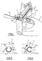
- the rod is presented according to its small size, as can be seen in the figure 3, so that it can pass directly through the first 12a, 13a in the form of a lateral opening commitment of the or each imprint of the second organ, without intervention of the assembly operator.
- this rod is fully engaged in the or each imprint, it is found in the second 12b, 13b thereof, so the operator can then operate the movement lever 15 angular of this rod 9 of the first orientation of engagement shown in Figure 3, towards a second locking orientation in the position shown in FIG. 4, which is therefore angularly offset by compared to the first one, to allow a blocking of this rod by clamping in this second portion 12b, 13b of the imprint, this having for example at least one dimension area smaller than the large dimension of the rod.
- this area of the imprint has then an evolving profile allowing progressive tightening of the rod during its angular displacement between its two directions.
- the operator can be forced to press the elastic tab 16 to free it from a corresponding offset from the first organ as previously stated.
- This release can also be automatic when the rod is engaged in the first portion in the form of a lateral opening of the imprint corresponding (figure 3).
- the tongue 16 can be adapted to come and get involved, as we can see in figure 4, by example in a 13c offset of this imprint, so ensure a locking in position of this rod in the imprint, in its second orientation.
- the stem can therefore no longer be released accidentally from the corresponding fingerprint.
- the operator can act on the tongue 16 to release it the corresponding offset 13c of this imprint, this which allows it to move the rod angularly to attach its second orientation to its first orientation to allow clearance of the rod and so disassembly of the column assembly from the fixing structure.
- the first and the second organs can be provided with only one recess for rotating reception of the rod and a single imprint of receipt thereof, respectively.
- the rod can also have forms different from those described, and be performed in a different way from that described.
- this rod can for example be molded in one piece of plastic instead to be made from a cut head blank and rolled.
- the elastic tongue 16 of this rod can also be adapted to extend into the second orientation of it, in the first portion in the form of a lateral opening for engaging the imprint corresponding, this tab then cooperating with the edges of this opening to prevent release accidental stem, imprint.
- a tab of this type can also be provided at each end of the rod.
- the fixing device according to the invention has a number of advantages with respect to the devices of the state of the art to the extent that the organ hooking rod one on the other is carried by one of these, which allows an automatic mounting of these members one on the other, locking in position of the organs relative to one another to the other by a simple angular displacement of the rod relative to these organs, between a first angular orientation of rod engagement carried by one of the organs in an imprint of the other organ, and a second orientation, tightening and locking of the rod in the hooking position, in this other member.
- the assembly under stress of the rod in the corresponding imprint provides a assembly without play of the parts one on the other.
- These means may for example include a shaped portion adapted to cooperate with a tool removable.
- Locking by tightening the rod in the or each print can also be obtained in a way different from that described, as well as the lock of it in its second orientation in this or these fingerprints of the second organ.
Landscapes
- Engineering & Computer Science (AREA)
- Chemical & Material Sciences (AREA)
- Combustion & Propulsion (AREA)
- Transportation (AREA)
- Mechanical Engineering (AREA)
- Clamps And Clips (AREA)
- Steering Controls (AREA)
Abstract
Description
- la figure 1 représente une vue en perspective illustrant un exemple de réalisation d'un dispositif de fixation de deux organes selon l'invention ;
- la figure 2 représente une vue en perspective d'un exemple de réalisation d'une tige d'accrochage entrant dans la constitution d'un tel dispositif ;
- les figures 3 et 4 illustrent le fonctionnement d'un tel dispositif de fixation ; et
- la figure 5 représente une vue de dessus d'un flan de tôle à partir duquel peut être réalisée une tige d'accrochage entrant dans la constitution du dispositif de fixation selon l'invention.
Claims (13)
- Dispositif de fixation de deux organes l'un sur l'autre, dont l'un (1) est un ensemble de colonne de direction de véhicule automobile et l'autre (2), une structure de fixation de celui-ci sur le reste de la structure du véhicule, caractérisé en ce qu'un premier (1) des organes comporte au moins un évidemment (7,8) de réception à rotation d'une tige d'accrochage (9) de celui-ci sur le second des organes (2), ladite tige (9) ayant une section aplatie présentant une petite et une grande dimensions, en ce que le second organe (2) comporte au moins une empreinte (12,13) de réception de cette tige (9), présentant une première portion (12a,13a) en forme d'ouverture latérale d'engagement de la tige (9) par sa petite dimension, dans une première orientation, et une seconde portion (12b,13b) de blocage par serrage de celle-ci, lorsqu'elle est déplacée angulairement de sa première orientation vers sa seconde orientation, décalée par rapport à la première, dans l'empreinte, et en ce que la tige (9) et l'un des organes (2) comportent des moyens (16,13c) de verrouillage de cette tige (9) dans sa seconde orientation.
- Dispositif de fixation selon la revendication 1, caractérisé en ce que la tige (9) et le premier organe (1) comportent des moyens complémentaires débrayables (16,7) de retenue de celle-ci dans une orientation prédéterminée par rapport à cet organe, correspondant à la première orientation d'engagement de cette tige (9) dans la ou chaque empreinte (12,13) du second organe.
- Dispositif de fixation selon la revendication 1 ou 2, caractérisé en ce que les moyens de verrouillage de la tige (9) dans la seconde orientation comprennent au moins une languette élastique (16) de la tige (9) adaptée pour coopérer avec un décrochement (13c) du second organe pour la verrouiller en position.
- Dispositif de fixation selon la revendication 2 ou 3, caractérisé en ce que les moyens complémentaires débrayables de retenue de la tige (9) dans l'orientation prédéterminée par rapport au premier organe (1) comprennent au moins une languette élastique (16) de la tige adaptée pour coopérer avec le ou l'un des évidements (7) de cet organe pour la retenir dans cette orientation.
- Dispositif de fixation selon les revendications 3 et 4, caractérisé en ce que la languette des moyens de verrouillage et des moyens de retenue est constituée par une seule et même languette (16) de la tige (9).
- Dispositif de fixation selon l'une quelconque des revendications précédente, caractérisé en ce que la tige (9) comporte à chacune de ses extrémités des moyens de butée axiale.
- Dispositif de fixation selon l'une quelconque des revendications précédentes, caractérisé en ce que la tige (9) comporte à au moins l'une de ses extrémités, des moyens de manoeuvre (15) permettant son déplacement entre ses première et seconde orientations.
- Dispositif de fixation selon la revendication 7, caractérisé en ce que les moyens de manoeuvre se présentent sous la forme d'un levier (15) actionnable pour un opérateur de montage.
- Dispositif de fixation selon les revendications 6,7 et 8, caractérisé en ce que les moyens de butée axiale prévus à l'une des extrémités de la tige (9) se présentent sous la forme d'une partie en saillie radiale (14) de celle-ci, tandis que les moyens de butée prévus à l'autre extrémité de la tige sont constitués par un épaulement (15a) du levier (15).
- Dispositif de fixation selon la revendication 9, caractérisé en ce que l'extrémité correspondante de la languette élastique (16) des moyens de verrouillage et de retenue est adaptée pour faire saillie au delà du levier (15) à travers un évidemment (15b) de celui-ci pour permettre son actionnement par un opérateur.
- Dispositif de fixation selon l'une quelconque des revendications précédentes, caractérisé en ce que la seconde portion (12b,13b) de la ou chaque empreinte présente au moins une zone de dimension inférieure à la grande dimension de la tige (9) et de profil évolutif permettant un serrage progressif de la tige (9).
- Dispositif de fixation selon l'une quelconque des revendications précédentes, caractérisé en ce que ladite tige d'accrochage (9) est réalisée à partir d'un flan de tôle découpé et roulé.
- Dispositif de fixation selon l'une quelconque des revendications 1 à 11, caractérisé en ce que ladite tige d'accrochage est réalisée en matière plastique par moulage.
Applications Claiming Priority (2)
| Application Number | Priority Date | Filing Date | Title |
|---|---|---|---|
| FR9703354A FR2761121A1 (fr) | 1997-03-19 | 1997-03-19 | Dispositif de fixation de deux organes l'un sur l'autre |
| FR9703354 | 1997-03-19 |
Publications (1)
| Publication Number | Publication Date |
|---|---|
| EP0866230A1 true EP0866230A1 (fr) | 1998-09-23 |
Family
ID=9504970
Family Applications (1)
| Application Number | Title | Priority Date | Filing Date |
|---|---|---|---|
| EP98400615A Withdrawn EP0866230A1 (fr) | 1997-03-19 | 1998-03-16 | Dispositif de fixation de deux organes l'un sur l'autre |
Country Status (2)
| Country | Link |
|---|---|
| EP (1) | EP0866230A1 (fr) |
| FR (1) | FR2761121A1 (fr) |
Cited By (1)
| Publication number | Priority date | Publication date | Assignee | Title |
|---|---|---|---|---|
| EP1847440A1 (fr) * | 2006-04-20 | 2007-10-24 | Delphi Technologies, Inc. | Ensemble de colonne de direction d'un véhicule |
Citations (5)
| Publication number | Priority date | Publication date | Assignee | Title |
|---|---|---|---|---|
| US2235949A (en) * | 1938-06-14 | 1941-03-25 | Shawlock Inc | Lock, coupling, and the like |
| GB2173578A (en) * | 1985-04-12 | 1986-10-15 | Ford Motor Co | Tiltable steering wheel |
| DE8803714U1 (fr) * | 1988-03-18 | 1988-05-26 | Gross, Ulrich, Dipl.-Designer, 8936 Langerringen, De | |
| JPH03183883A (ja) * | 1989-12-13 | 1991-08-09 | Wacoal Corp | 蝶番装置 |
| GB2263756A (en) * | 1992-01-24 | 1993-08-04 | Ford Motor Co | Adjustment mechanism for vehicle steering columns. |
-
1997
- 1997-03-19 FR FR9703354A patent/FR2761121A1/fr active Pending
-
1998
- 1998-03-16 EP EP98400615A patent/EP0866230A1/fr not_active Withdrawn
Patent Citations (5)
| Publication number | Priority date | Publication date | Assignee | Title |
|---|---|---|---|---|
| US2235949A (en) * | 1938-06-14 | 1941-03-25 | Shawlock Inc | Lock, coupling, and the like |
| GB2173578A (en) * | 1985-04-12 | 1986-10-15 | Ford Motor Co | Tiltable steering wheel |
| DE8803714U1 (fr) * | 1988-03-18 | 1988-05-26 | Gross, Ulrich, Dipl.-Designer, 8936 Langerringen, De | |
| JPH03183883A (ja) * | 1989-12-13 | 1991-08-09 | Wacoal Corp | 蝶番装置 |
| GB2263756A (en) * | 1992-01-24 | 1993-08-04 | Ford Motor Co | Adjustment mechanism for vehicle steering columns. |
Non-Patent Citations (1)
| Title |
|---|
| PATENT ABSTRACTS OF JAPAN vol. 015, no. 437 (M - 1176) 7 November 1991 (1991-11-07) * |
Cited By (1)
| Publication number | Priority date | Publication date | Assignee | Title |
|---|---|---|---|---|
| EP1847440A1 (fr) * | 2006-04-20 | 2007-10-24 | Delphi Technologies, Inc. | Ensemble de colonne de direction d'un véhicule |
Also Published As
| Publication number | Publication date |
|---|---|
| FR2761121A1 (fr) | 1998-09-25 |
Similar Documents
| Publication | Publication Date | Title |
|---|---|---|
| EP1574638B1 (fr) | Ensemble de support de poignée, organe de blocage et élément externe de poignée et procédé de fixation de l'élément externe dans le support de poignée. | |
| EP0497655B1 (fr) | Enjoliveur de roue, notamment de véhicule automobile | |
| FR2900897A1 (fr) | Fixation glissante d'une aile a une caisse en blanc de vehicule automobile et procede de fixation utilisant une telle fixation | |
| FR2843725A1 (fr) | Agencement pour l'accouplement d'une tige de commande d'un servomoteur | |
| EP0943758B1 (fr) | Verrou à débrayage axial perfectionné pour un mécanisme de serrure de véhicule automobile | |
| EP0866230A1 (fr) | Dispositif de fixation de deux organes l'un sur l'autre | |
| EP0296961B1 (fr) | Dispositif de fixation | |
| WO2004081325A1 (fr) | Serrure renforcee pour ouvrant de vehicule automobile | |
| EP1721795B1 (fr) | Dispositif et procédé de fixation d'un mécanisme d'essuie-vitre sur une partie de caisse de véhicule, et véhicule automobile équipé d'un tel dispositif | |
| FR2796012A1 (fr) | Dispositif de fixation dans une chape d'un axe de montage d'une pedale de vehicule | |
| FR2733285A1 (fr) | Dispositif de fixation mecanique rigide destine a une rotule, ensemble le comprenant et procedes de montage et demontage | |
| EP0365396B1 (fr) | Platine de frein à main pour véhicule automobile | |
| FR2652374A1 (fr) | Poignee pour portiere de vehicule a moteur. | |
| FR2900681A1 (fr) | Raccord de tringle d'huisserie | |
| EP0794337A1 (fr) | Attache rapide de type à baionnette | |
| FR3049016B1 (fr) | Dispositif de fixation d'un soufflet sur un pommeau de levier de commande de boite de vitesses. | |
| EP4114693B1 (fr) | Support de boite a rotule, bielle et procede d'assemblage correspondants | |
| EP0820915A1 (fr) | Dispositif de fixation d'un moyeu de volant de direction de véhicule, sur une extrémité d'un arbre de direction | |
| EP0828050B1 (fr) | Charnière de porte, notamment pour véhicule automobile | |
| EP0913591A1 (fr) | Attache rapide pour la fixation de deux organes l'un sur l'autre | |
| FR2688255A1 (fr) | Support a alignement automatique pour poignee de porte, fenetre et analogues. | |
| FR2715111A1 (fr) | Procédé pour fixer un tableau de commande de chauffage-ventilation sur la planche de bord d'un véhicule. | |
| FR2737869A1 (fr) | Retroviseur exterieur pour vehicules automobiles | |
| FR3066975A1 (fr) | Palier d'une timonerie d'un mecanisme d'essuyage comprenant un bras de maintien de la timonerie dans une position de transport, sous-ensemble de timonerie et timonerie associes, et procede de blocage en position de transport de cette timonerie | |
| FR2746743A1 (fr) | Bras d'essuie-glace, notamment pour vehicule automobile |
Legal Events
| Date | Code | Title | Description |
|---|---|---|---|
| PUAI | Public reference made under article 153(3) epc to a published international application that has entered the european phase |
Free format text: ORIGINAL CODE: 0009012 |
|
| AK | Designated contracting states |
Kind code of ref document: A1 Designated state(s): AT BE CH LI |
|
| AX | Request for extension of the european patent |
Free format text: AL;LT;LV;MK;RO;SI |
|
| 17P | Request for examination filed |
Effective date: 19981016 |
|
| AKX | Designation fees paid |
Free format text: AT BE CH LI |
|
| RBV | Designated contracting states (corrected) |
Designated state(s): AT BE CH LI |
|
| RBV | Designated contracting states (corrected) |
Designated state(s): DE FR GB |
|
| REG | Reference to a national code |
Ref country code: DE Ref legal event code: 8566 |
|
| STAA | Information on the status of an ep patent application or granted ep patent |
Free format text: STATUS: THE APPLICATION HAS BEEN WITHDRAWN |
|
| 18W | Application withdrawn |
Withdrawal date: 20000217 |