EP0866005B1 - Vorrichtung zum Handhaben von Gegenständen - Google Patents
Vorrichtung zum Handhaben von Gegenständen Download PDFInfo
- Publication number
- EP0866005B1 EP0866005B1 EP19980301646 EP98301646A EP0866005B1 EP 0866005 B1 EP0866005 B1 EP 0866005B1 EP 19980301646 EP19980301646 EP 19980301646 EP 98301646 A EP98301646 A EP 98301646A EP 0866005 B1 EP0866005 B1 EP 0866005B1
- Authority
- EP
- European Patent Office
- Prior art keywords
- conduit
- articles
- closure
- gate
- rotatable
- Prior art date
- Legal status (The legal status is an assumption and is not a legal conclusion. Google has not performed a legal analysis and makes no representation as to the accuracy of the status listed.)
- Expired - Lifetime
Links
- 238000007789 sealing Methods 0.000 claims 1
- 238000011144 upstream manufacturing Methods 0.000 claims 1
- 238000005303 weighing Methods 0.000 description 4
- 238000004519 manufacturing process Methods 0.000 description 3
- 230000001133 acceleration Effects 0.000 description 1
- 230000004888 barrier function Effects 0.000 description 1
- 230000007257 malfunction Effects 0.000 description 1
- 238000004806 packaging method and process Methods 0.000 description 1
- 230000002093 peripheral effect Effects 0.000 description 1
- 238000000926 separation method Methods 0.000 description 1
Images


Classifications
-
- B—PERFORMING OPERATIONS; TRANSPORTING
- B65—CONVEYING; PACKING; STORING; HANDLING THIN OR FILAMENTARY MATERIAL
- B65G—TRANSPORT OR STORAGE DEVICES, e.g. CONVEYORS FOR LOADING OR TIPPING, SHOP CONVEYOR SYSTEMS OR PNEUMATIC TUBE CONVEYORS
- B65G53/00—Conveying materials in bulk through troughs, pipes or tubes by floating the materials or by flow of gas, liquid or foam
- B65G53/34—Details
-
- B—PERFORMING OPERATIONS; TRANSPORTING
- B65—CONVEYING; PACKING; STORING; HANDLING THIN OR FILAMENTARY MATERIAL
- B65G—TRANSPORT OR STORAGE DEVICES, e.g. CONVEYORS FOR LOADING OR TIPPING, SHOP CONVEYOR SYSTEMS OR PNEUMATIC TUBE CONVEYORS
- B65G53/00—Conveying materials in bulk through troughs, pipes or tubes by floating the materials or by flow of gas, liquid or foam
- B65G53/04—Conveying materials in bulk pneumatically through pipes or tubes; Air slides
- B65G53/06—Gas pressure systems operating without fluidisation of the materials
- B65G53/10—Gas pressure systems operating without fluidisation of the materials with pneumatic injection of the materials by the propelling gas
- B65G53/14—Gas pressure systems operating without fluidisation of the materials with pneumatic injection of the materials by the propelling gas the gas flow inducing feed of the materials by suction effect
-
- B—PERFORMING OPERATIONS; TRANSPORTING
- B65—CONVEYING; PACKING; STORING; HANDLING THIN OR FILAMENTARY MATERIAL
- B65G—TRANSPORT OR STORAGE DEVICES, e.g. CONVEYORS FOR LOADING OR TIPPING, SHOP CONVEYOR SYSTEMS OR PNEUMATIC TUBE CONVEYORS
- B65G53/00—Conveying materials in bulk through troughs, pipes or tubes by floating the materials or by flow of gas, liquid or foam
- B65G53/34—Details
- B65G53/40—Feeding or discharging devices
- B65G53/46—Gates or sluices, e.g. rotary wheels
-
- B—PERFORMING OPERATIONS; TRANSPORTING
- B65—CONVEYING; PACKING; STORING; HANDLING THIN OR FILAMENTARY MATERIAL
- B65G—TRANSPORT OR STORAGE DEVICES, e.g. CONVEYORS FOR LOADING OR TIPPING, SHOP CONVEYOR SYSTEMS OR PNEUMATIC TUBE CONVEYORS
- B65G53/00—Conveying materials in bulk through troughs, pipes or tubes by floating the materials or by flow of gas, liquid or foam
- B65G53/34—Details
- B65G53/60—Devices for separating the materials from propellant gas
Definitions
- This invention relates to the handling of a series of individual articles, eg. to control the movement of the articles or to collect batches of the articles.
- the invention is concerned with the batching of articles that are being manufactured at high production rates.
- the articles are relatively fragile it can be difficult to collect them in batches of predetermined quantities as they emerge from the production process, eg. for weighing and/or packaging.
- apparatus for releasing articles in batches comprising a conduit having an exit provided with a closure gate rotatable to open and close the conduit, characterised in that said gate comprises at least one closure member mounted on a rotary axis at or adjacent a side wall of the conduit to be rotatable about said axis generally in the direction of movement of the articles through the conduit to a position extending across the conduit to close the exit for the articles, and is further rotatable in the same direction from said closing position to open the exit.
- closure members arranged side by side at the exit passage and rotatable in opposite directions to each other for said opening and closing of the exit.
- the closure member or members can thus be employed to temporarily cut off the flow of articles when a predetermined batch has been counted through.
- one or more rotatable members as a gate to stop the flow of articles from the conduit it is possible to handle a continuous stream of articles and to batch predetermined quantities of articles from that stream.
- the conduit exit can be closed by the gate while the batch of articles is transferred away or is weighed or subjected to other tests, the continuing stream of articles arriving meanwhile being accumulated at the gate. It is only necessary to ensure that each batch has moved on further in time to accommodate the following batch.
- the accumulated articles can be cleared from the gate rapidly as it is opened. Also, if the or each member moves in the same direction to close the gate its motion can be more easily timed to synchronise with brief intervals between the arrival of successive articles, in order to avoid the risk of trapping articles during the closure of the gate.
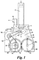
- the apparatus illustrated in Figs. 1 and 2 of the drawings is intended to be positioned between a vertical flow-fill apparatus (not shown) which delivers a stream of articles into the top entry of a tube 2 forming the entry duct of a vertical conduit through the apparatus, and a conveyor (not shown) which lies below the bottom of the conduit.
- the flow-fill apparatus and the conveyor can each be of conventional design and do not need to be described further. They may be replaced by other apparatus and devices if desired, for example a weighing hopper can be placed below the conduit exit.
- the tube 2 leads downwards through a suction chamber 4 which forms an annulus around a lower region of the tube.
- a pair of opposed comb plates 24 are rotatable on parallel shafts 26,26a to form a closure gate. From the central shaft of each comb plate corresponding sets of parallel teeth 30 project in diametrically opposite directions.
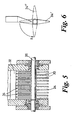
- the comb plates 24 are shown in a vertical position in Fig. 1, in which they leave the outlet of the exit chamber open. In Fig. 6 the comb plate is shown in full lines in this position, indicated by the reference 24', and is shown in phantom lines and indicated by the reference 24" in a position in which it forms a barrier across the outlet.
- Side walls 32 of the exit chamber extending upwards from close to the comb plate shafts 28 are slotted to form a series of fins 34 (Fig. 5) which allow free passage for the comb plates as these are rotated on their mountings through the vertical position.
- rollers are driven by a belt drive 54 from a constant speed motor 56.
- a further belt drive 58 from the motor 56 drives the gate comb plates 24 which are similarly coupled together by toothed gears 60 to rotate synchronously in opposite directions.
- the comb plates move in 90° steps between the vertical and horizontal positions shown in Figs. 6, for which purpose they are driven through a "CB6 Super" wrap spring clutch 66 manufactured by Warner Electric Rotary Motion Division of Pitman, New Jersey.
- the clutch 66 comprises a stop collar 68, (Fig. 4) having four equally spaced stop faces 70 for movement in 90° steps in known manner.
- the gate belt drive 58 applies a continuous rotation to a pulley 72 rotatably mounted on the shaft 26 of the rear comb plate 24.
- a solenoid-operated pawl 74 (Fig. 4) is engageable with the stop collar 68 of the clutch to hold it fixed, during which time the drive is not transmitted from the pulley 72 and both comb plates 24 are held braked.
- the pawl 74 releases the stop collar 68 the brake imposed by the clutch 66 is released and the pulley drive is engaged with the shaft 26 of the rear comb plate to rotate the shaft and the stop collar 76 as one.
- Both comb plates of course rotate together in opposite directions and when a 90' rotation has been completed, the pawl 74 arrests the stop collar 68.
- the clutch then instantaneously brakes the comb plates and decouples them from the drive pulley 72
- a first operation of the clutch will rotate the comb plates through 90° in the directions indicated by the arrows X in Figs. 1 and 6 to close the gate.
- the next operation of the clutch will reopen the gate as the comb plates are rotated in the same direction through a further 90°, so that the comb plates in the path of the articles always move generally in the direction of movement of the articles.
- the comb plates 24 are normally held in their vertical positions, leaving open the outlet from the exit chamber 22 while a required number of articles are counted through the apparatus by conventional counter means (not shown), or by a timer if appropriate, and into whatever receiver (not shown) is provided for them below the conduit. At the end of the required count the comb plates are rotated to the horizontal position, so holding back further articles, while the batch of articles counted out is transferred away, and possibly weighed. Once the receiver has been cleared, eg.
- the receiving conveyor has moved on or the weighing hopper has been emptied, the comb plates rotate to open the gate again to release the first articles of the next batch which will have accumulated in the conduit in the meanwhile, and the gate is then kept open until the remainder of that batch have passed through.
- the comb plates 24 move through the exit chamber in the general direction of movement of the articles, and the peripheral speed of the comb plates is preferably approximately equal to the speed of descent of the articles past them. By moving at a similar speed to the articles it can be ensured that the comb plates will not block the discharge of collected articles when the gate is opened and that they impose a precise cut off on the flow of articles from the apparatus when the gate is closed.
- a sensor 78 (Fig. 1) is able to detect that the closure gate is in an open state. If the gate mechanism should malfunction, it is thereby possible to automatically stop the flow of articles into the apparatus by employing the sensor output to actuate means (not shown) for stopping the production of further articles or for diverting the flow of articles elsewhere.
- the drive arrangement employing the wrap spring clutch 66 with a continuous input drive allows the gate to be opened and closed extremely rapidly without risk of trapping articles between the comb plates, in particular when the flow is being stopped.
- the acceleration given to the articles by the suction acting in the tube 2 increases the separation of the articles and so makes it easier to close the gate in the interval between succeeding articles. Consequently, the apparatus can be employed with high rates of article throughflow, for example of the order of 900 articles per minute, delivering batches of ten articles at a time, without making it necessary to interrupt the passage of articles into the apparatus to count through each batch of articles accurately.
- Fig. 7 illustrates a modified form of apparatus according to the invention in which parts which have already been described are indicated by the same reference numbers.
- the drawing indicates that the orientation of the path through the suction chamber can be varied if desired, and that it is possible to employ a longer suction tube 102 if it is required to deliver the batches of articles to a receiving location remote from the article-producing apparatus, such as to a container 104 on a conveyor 106.
- the drive arrangement for the comb plates 24 may be as already described.
Landscapes
- Engineering & Computer Science (AREA)
- Mechanical Engineering (AREA)
- Air Transport Of Granular Materials (AREA)
- Containers And Plastic Fillers For Packaging (AREA)
- Filling Or Emptying Of Bunkers, Hoppers, And Tanks (AREA)
Claims (7)
- Vorrichtung zum Freigeben von Gegenständen in Chargen, mit einer Leitung (2) mit einem Ausgang (22), der mit einer zum Öffnen und Schließen der Leitung drehbaren Verschlussschranke versehen ist, dadurch gekennzeichnet, dass die Schranke mindestens ein Verschlusselement (24) aufweist, das auf einer drehbaren Achse (26, 26a) an oder benachbart einer Seitenwand (32) der Leitung so befestigt ist, dass es um diese Achse im Allgemeinen in der Bewegungsrichtung der Gegenstände durch die Leitung in eine Position drehbar ist, die sich quer zur Leitung zum Schließen des Ausgangs für die Gegenstände erstreckt, und in derselben Richtung aus der Schließposition zum Öffnen des Ausgangs weiter drehbar ist, wobei das mindestens eine Verschlusselement eine Reihe von Elementen (24) umfasst, die in Abständen entlang der Drehachse (26, 26a) vorliegen und von dieser nach außen ragen, und eine benachbarte Wand (32) der Leitung, die zur Verschlussschranke führt, eine Reihe von im Abstand voneinander befindlichen Elementen (34) aufweist, die mit den Elementen des Verschlusselements kämmen, wenn dieses gedreht wird.
- Vorrichtung nach Anspruch 1, wobei das mindestens eine Verschlusselement ein im Wesentlichen planes Element ist.
- Vorrichtung nach Anspruch 1 oder 2, wobei das mindestens eine Verschlusselement aus einer Position, die im Wesentlichen koplanar mit einem angrenzenden Bereich der Leitungswand ist, in die Schließposition drehbar ist.
- Vorrichtung nach einem der Ansprüche 1 bis 3, wobei das mindestens eine Verschlusselement diametral gegenüberliegende Elemente (24) aufweist, die symmetrisch in Bezug auf die Drehachse (26, 26a) angeordnet sind, wobei das Verschlusselement zwischen Öffnungs- und Schließpositionen in gleichen 90°-Schritten drehbar ist.
- Vorrichtung nach einem der vorhergehenden Ansprüche, welche ein Paar von drehbaren Verschlusselementen (24), die auf Drehachsen (26, 26a) an oder benachbart gegenüberliegen Seitenwänden der Leitung befestigt sind, und Mittel (56, 58) zum gemeinsamen Drehen der Verschlusselemente in entgegengesetzte Richtungen zum gemeinsamen Öffnen und Schließen des Ausgangs umfasst.
- Vorrichtung nach einem der vorhergehenden Ansprüche, wobei die Leitung einen abwärts gerichteten Weg für die durch das Öffnen der Verschlussschranke freigegebenen Gegenstände vorsieht.
- Vorrichtung nach einem der vorhergehenden Ansprüche, welche Saugmittel (4, 16) in einem zur Leitung führenden Weg für die Gegenstände, und sich in Gegenrichtung drehende Rollen (52) aufweist, die diesen Weg vor der Verschlussschranke zumindest teilweise verschließen, und wobei mindestens eine der Rollen einen nachgiebigen Umfang hat, um ein Passieren von Gegenständen zwischen den Rollen durch Verformen des Umfangs oder der Umfänge zu ermöglichen.
Priority Applications (1)
| Application Number | Priority Date | Filing Date | Title |
|---|---|---|---|
| EP19980301646 EP0866005B1 (de) | 1997-03-19 | 1998-03-05 | Vorrichtung zum Handhaben von Gegenständen |
Applications Claiming Priority (3)
| Application Number | Priority Date | Filing Date | Title |
|---|---|---|---|
| EP97301861 | 1997-03-19 | ||
| EP97301861 | 1997-03-19 | ||
| EP19980301646 EP0866005B1 (de) | 1997-03-19 | 1998-03-05 | Vorrichtung zum Handhaben von Gegenständen |
Publications (3)
| Publication Number | Publication Date |
|---|---|
| EP0866005A2 EP0866005A2 (de) | 1998-09-23 |
| EP0866005A3 EP0866005A3 (de) | 2000-05-17 |
| EP0866005B1 true EP0866005B1 (de) | 2004-06-02 |
Family
ID=26147349
Family Applications (1)
| Application Number | Title | Priority Date | Filing Date |
|---|---|---|---|
| EP19980301646 Expired - Lifetime EP0866005B1 (de) | 1997-03-19 | 1998-03-05 | Vorrichtung zum Handhaben von Gegenständen |
Country Status (1)
| Country | Link |
|---|---|
| EP (1) | EP0866005B1 (de) |
Family Cites Families (2)
| Publication number | Priority date | Publication date | Assignee | Title |
|---|---|---|---|---|
| DE1294883B (de) * | 1966-08-03 | 1969-05-08 | Steinmueller Gmbh L & C | Schuettgutrohrschleuse |
| US5156499A (en) * | 1991-03-19 | 1992-10-20 | Miklich Henry A | Roller injection air lock |
-
1998
- 1998-03-05 EP EP19980301646 patent/EP0866005B1/de not_active Expired - Lifetime
Also Published As
| Publication number | Publication date |
|---|---|
| EP0866005A2 (de) | 1998-09-23 |
| EP0866005A3 (de) | 2000-05-17 |
Similar Documents
| Publication | Publication Date | Title |
|---|---|---|
| EP0752967B1 (de) | Abgabevorrichtung | |
| CA3134676C (en) | Gating system for accumulating items and related filling machine and methods | |
| US4085563A (en) | Cookie dispensing apparatus | |
| US6053302A (en) | Object singulating and counting device | |
| CN1200807A (zh) | 称重小制品例如胶囊的装置 | |
| US5653328A (en) | Equipment for forming ordered groups of articles from a generally flat flow of articles, particularly for automatic packaging systems | |
| EP2755904A1 (de) | Verfahren zum automatischen verpacken von sanitärartikeln und entsprechendes system | |
| JPH0536021B2 (de) | ||
| US5997238A (en) | On-line package stacking apparatus and method | |
| US7516836B2 (en) | Centrifugal filling apparatus and method | |
| US3266614A (en) | Article spacing system | |
| US3018595A (en) | Package filling apparatus | |
| EP0349800A1 (de) | Pulverzuführeinrichtung | |
| US6296423B1 (en) | Article handling apparatus | |
| EP0866005A2 (de) | Vorrichtung zum Handhaben von Gegenständen | |
| US2899784A (en) | Method and apparatus for counting and packaging articles | |
| USRE25013E (en) | Apparatus for counting and packaging articles | |
| US2111921A (en) | Automatic weighing apparatus | |
| TW202139961A (zh) | 錠劑送出裝置、具有錠劑送出裝置的藥劑分包機、錠劑分類裝置 | |
| JP4330884B2 (ja) | 薬剤分配装置及び薬剤分包装置 | |
| JP4330886B2 (ja) | 薬剤分配装置及び薬剤分包装置 | |
| JP2021053114A (ja) | 薬剤供給装置及び薬剤分包装置 | |
| JP4330885B2 (ja) | 薬剤分配装置及び薬剤分包装置 | |
| JP5634719B2 (ja) | ホッパおよび計量装置 | |
| JP4486152B2 (ja) | 薬剤分配装置及び薬剤分包装置 |
Legal Events
| Date | Code | Title | Description |
|---|---|---|---|
| PUAI | Public reference made under article 153(3) epc to a published international application that has entered the european phase |
Free format text: ORIGINAL CODE: 0009012 |
|
| AK | Designated contracting states |
Kind code of ref document: A2 Designated state(s): DE ES FR GB IT |
|
| AX | Request for extension of the european patent |
Free format text: AL;LT;LV;MK;RO;SI |
|
| 17P | Request for examination filed |
Effective date: 19991203 |
|
| PUAL | Search report despatched |
Free format text: ORIGINAL CODE: 0009013 |
|
| AK | Designated contracting states |
Kind code of ref document: A3 Designated state(s): AT BE CH DE DK ES FI FR GB GR IE IT LI LU MC NL PT SE |
|
| AX | Request for extension of the european patent |
Free format text: AL;LT;LV;MK;RO;SI |
|
| AKX | Designation fees paid |
Free format text: DE ES FR GB IT |
|
| RAP1 | Party data changed (applicant data changed or rights of an application transferred) |
Owner name: UNILEVER N.V. Owner name: UNILEVER PLC |
|
| 17Q | First examination report despatched |
Effective date: 20030428 |
|
| GRAP | Despatch of communication of intention to grant a patent |
Free format text: ORIGINAL CODE: EPIDOSNIGR1 |
|
| GRAS | Grant fee paid |
Free format text: ORIGINAL CODE: EPIDOSNIGR3 |
|
| GRAA | (expected) grant |
Free format text: ORIGINAL CODE: 0009210 |
|
| AK | Designated contracting states |
Kind code of ref document: B1 Designated state(s): DE ES FR GB IT |
|
| PG25 | Lapsed in a contracting state [announced via postgrant information from national office to epo] |
Ref country code: FR Free format text: LAPSE BECAUSE OF FAILURE TO SUBMIT A TRANSLATION OF THE DESCRIPTION OR TO PAY THE FEE WITHIN THE PRESCRIBED TIME-LIMIT Effective date: 20040602 |
|
| REG | Reference to a national code |
Ref country code: GB Ref legal event code: FG4D |
|
| REF | Corresponds to: |
Ref document number: 69824223 Country of ref document: DE Date of ref document: 20040708 Kind code of ref document: P |
|
| PG25 | Lapsed in a contracting state [announced via postgrant information from national office to epo] |
Ref country code: ES Free format text: LAPSE BECAUSE OF FAILURE TO SUBMIT A TRANSLATION OF THE DESCRIPTION OR TO PAY THE FEE WITHIN THE PRESCRIBED TIME-LIMIT Effective date: 20040913 |
|
| PLBE | No opposition filed within time limit |
Free format text: ORIGINAL CODE: 0009261 |
|
| STAA | Information on the status of an ep patent application or granted ep patent |
Free format text: STATUS: NO OPPOSITION FILED WITHIN TIME LIMIT |
|
| 26N | No opposition filed |
Effective date: 20050303 |
|
| EN | Fr: translation not filed | ||
| PGFP | Annual fee paid to national office [announced via postgrant information from national office to epo] |
Ref country code: GB Payment date: 20100326 Year of fee payment: 13 |
|
| PGFP | Annual fee paid to national office [announced via postgrant information from national office to epo] |
Ref country code: IT Payment date: 20100329 Year of fee payment: 13 Ref country code: DE Payment date: 20100329 Year of fee payment: 13 |
|
| GBPC | Gb: european patent ceased through non-payment of renewal fee |
Effective date: 20110305 |
|
| PG25 | Lapsed in a contracting state [announced via postgrant information from national office to epo] |
Ref country code: DE Free format text: LAPSE BECAUSE OF NON-PAYMENT OF DUE FEES Effective date: 20111001 |
|
| REG | Reference to a national code |
Ref country code: DE Ref legal event code: R119 Ref document number: 69824223 Country of ref document: DE Effective date: 20111001 |
|
| PG25 | Lapsed in a contracting state [announced via postgrant information from national office to epo] |
Ref country code: IT Free format text: LAPSE BECAUSE OF NON-PAYMENT OF DUE FEES Effective date: 20110305 Ref country code: GB Free format text: LAPSE BECAUSE OF NON-PAYMENT OF DUE FEES Effective date: 20110305 |