EP0864744B1 - Improvements to devices for controlling a contactor for a vehicle starter motor - Google Patents
Improvements to devices for controlling a contactor for a vehicle starter motor Download PDFInfo
- Publication number
- EP0864744B1 EP0864744B1 EP98400553A EP98400553A EP0864744B1 EP 0864744 B1 EP0864744 B1 EP 0864744B1 EP 98400553 A EP98400553 A EP 98400553A EP 98400553 A EP98400553 A EP 98400553A EP 0864744 B1 EP0864744 B1 EP 0864744B1
- Authority
- EP
- European Patent Office
- Prior art keywords
- contactor
- coil
- transistor
- controlling
- starter motor
- Prior art date
- Legal status (The legal status is an assumption and is not a legal conclusion. Google has not performed a legal analysis and makes no representation as to the accuracy of the status listed.)
- Expired - Lifetime
Links
Images
Classifications
-
- F—MECHANICAL ENGINEERING; LIGHTING; HEATING; WEAPONS; BLASTING
- F02—COMBUSTION ENGINES; HOT-GAS OR COMBUSTION-PRODUCT ENGINE PLANTS
- F02N—STARTING OF COMBUSTION ENGINES; STARTING AIDS FOR SUCH ENGINES, NOT OTHERWISE PROVIDED FOR
- F02N11/00—Starting of engines by means of electric motors
- F02N11/08—Circuits or control means specially adapted for starting of engines
- F02N11/087—Details of the switching means in starting circuits, e.g. relays or electronic switches
-
- F—MECHANICAL ENGINEERING; LIGHTING; HEATING; WEAPONS; BLASTING
- F02—COMBUSTION ENGINES; HOT-GAS OR COMBUSTION-PRODUCT ENGINE PLANTS
- F02N—STARTING OF COMBUSTION ENGINES; STARTING AIDS FOR SUCH ENGINES, NOT OTHERWISE PROVIDED FOR
- F02N11/00—Starting of engines by means of electric motors
- F02N11/10—Safety devices
- F02N11/106—Safety devices for stopping or interrupting starter actuation
-
- F—MECHANICAL ENGINEERING; LIGHTING; HEATING; WEAPONS; BLASTING
- F02—COMBUSTION ENGINES; HOT-GAS OR COMBUSTION-PRODUCT ENGINE PLANTS
- F02N—STARTING OF COMBUSTION ENGINES; STARTING AIDS FOR SUCH ENGINES, NOT OTHERWISE PROVIDED FOR
- F02N2200/00—Parameters used for control of starting apparatus
- F02N2200/06—Parameters used for control of starting apparatus said parameters being related to the power supply or driving circuits for the starter
- F02N2200/063—Battery voltage
Definitions
- the present invention relates to devices for controlling a vehicle starter switch automobile.
- a starter D which includes an electric motor M mounted between a terminal B + power supply to battery voltage and ground.
- Electric motor supply is controlled by a contactor 1 mounted between said terminal B + and the motor M.
- This contactor 1 is a relay which includes a plunger core (not shown) actuated by a winding call 2 and a holding coil 3 for pushing and maintain a power contact in the closed position 1a.
- the call winding 2 is mounted between the end of the motor M which is opposite to the ground and the winding 3, said coil 3 being connected to ground by its end opposite.
- the coils 2 and 3 are connected to the source of a transistor 4 whose drain is connected to terminal B +, via the ignition key switch 6.
- This transistor 4 is controlled, for example in all or nothing, by a microprocessor 5 - also connected to the supply terminal B + - which injects a voltage of control on the gate of transistor 4.
- This microprocessor 5 is for example, as illustrated in FIG. 1, integrated with relay 1 and transistor 4 inside of the starter housing. It can also be located outside the starter, anywhere in the vehicle.
- the call coil 2 is chosen with very resistance lower than that of the holding coil 3.
- the transistor 4 supplying only the coil of maintenance 3, whose current consumption is low, the heating of said transistor 4 is considerably reduced.
- the transistor 4 is then very quickly destroyed by excessive heating.
- US-A-5,345,901 describes such a device, but uses a relay instead of a transistor. To avoid overheating of the call coil of the power under the above conditions, the voltage difference between the power contact terminals is monitored and the relay is blocked if after closing the contact switch, this voltage difference is not below a predetermined threshold.
- An object of the invention is to overcome this disadvantage.
- said contactor comprising a contact power which controls the supply of the electric motor of the starter and at least one coil which controls the displacement of said contact
- said device comprising a unit for managing the starter control, as well that a transistor, controlled by said unit, which controls the supply of the contactor coil (s), characterized in that the management unit includes means to block the transistor when the fall of voltage at a point supplied with battery voltage between two successive instants following the closing of the contact switch is below a given threshold.
- the invention also relates to a device for control of the power supply of a vehicle starter automobile which comprises a contactor comprising a power contact which controls the motor supply starter motor and at least one coil which controls the movement of said contact, characterized in that that it further comprises a device for controlling contactor of the aforementioned type.
- the control device is of a structure general similar to that illustrated in Figure 1.
- the microprocessor 5 On its input which is connected to terminal B + by through the ignition key switch 6, the microprocessor 5 includes an analog converter digital which allows him to measure the voltage on terminal B + when switch 6 is closed.
- the microprocessor 5 starts the start-up process by closing the transistor 4 (step 15 on the flowchart in FIG. 3) and measures the voltage U 2 in a time T 2 following the closure of switch 6 (step 16).
- the time T 2 corresponds to approximately 10 to 20 milliseconds after the transistor 4 has switched to its on state.
- the microprocessor 5 checks the appearance of a significant voltage drop after a time T s , T s generally being between a few tenths of seconds and a few seconds.
- the microprocessor 5 checks whether or not the voltage at time T 2 + T s is greater than U 2 - dU, where dU corresponds to the expected minimum voltage drop (step 17).
- the microprocessor 5 blocks the transistor 4 to avoid its deterioration (step 18).
- microprocessor 5 continues the start-up process (step 19).
- the time T s is obviously determined so that the heating remains low enough so that the transistor 4 is not damaged.
- This solution has the advantage of allowing do not damage the power transistor 4 by a extended operation in call mode and does not require no additional components to achieve this function.
- the relay can then have only one coil instead a call coil and a holding coil.
- the device for electronic starter control illustrated in the figure 1 has the advantage of being of the "autonomous" type, that is to say not to require any other electrical connection than those used by conventional starters not electronic, namely a control cable allowing the connection with the vehicle's contact switch, a power supply cable connected to a terminal such as the positive terminal of the battery, and a return to ground by the carcass of the starter.
Description
La présente invention est relative aux dispositifs pour la commande d'un contacteur de démarreur de véhicule automobile.The present invention relates to devices for controlling a vehicle starter switch automobile.
On a illustré sur la figure 1 un démarreur D, qui comporte un moteur électrique M monté entre une borne B+ d'alimentation à la tension de la batterie et la masse.Illustrated in Figure 1 a starter D, which includes an electric motor M mounted between a terminal B + power supply to battery voltage and ground.
L'alimentation du moteur électrique est commandée
par un contacteur 1 monté entre ladite borne B+ et le
moteur M.Electric motor supply is controlled
by a
Ce contacteur 1 est un relais qui comporte un
noyau plongeur (non représenté) actionné par un bobinage
d'appel 2 et un bobinage de maintien 3 pour pousser et
maintenir en position de fermeture un contact de puissance
1a.This
Le bobinage d'appel 2 est monté entre l'extrémité
du moteur M qui est opposée à la masse et le bobinage 3,
ledit bobinage 3 étant relié à la masse par son extrémité
opposée.The call winding 2 is mounted between the end
of the motor M which is opposite to the ground and the winding 3,
said
A leur extrémité commune, les bobinages 2 et 3
sont reliés à la source d'un transistor 4 dont le drain
est relié à la borne B+, par l'intermédiaire de
l'interrupteur de clé de contact 6.At their common end, the
Ce transistor 4 est commandé, par exemple en tout
ou rien, par un microprocesseur 5 - également relié à la
borne d'alimentation B+ - qui injecte une tension de
commande sur la grille du transistor 4. Ce microprocesseur
5 est par exemple, ainsi qu'illustré sur la figure 1,
intégré avec le relais 1 et le transistor 4 à l'intérieur
de la carcasse du démarreur. Il peut également être
disposé hors du démarreur, en un endroit quelconque du
véhicule.This
Lorsque ledit transistor 4 devient passant, la
bobine d'appel 2 et la bobine de maintien 3 sont
alimentées simultanément.When said
Pour permettre une force d'appel importante, la
bobine d'appel 2 est choisie avec une résistance très
inférieure à celle de la bobine de maintien 3. La
résistance du moteur électrique M à l'arrêt étant
négligeable par rapport à la résistance des bobinages 2 et
3, l'intensité qui passe dans ledit transistor 4 est
maximale tant que le contacteur 1 n'est pas fermé. Ceci
produit un échauffement important et rapide du transistor
4.To allow a significant appeal force, the
Les forces développées par les bobines 2 et 3 du
contacteur mettent en mouvement le noyau plongeur qui, en
fin de course, ferme le contact de puissance 1a.The forces developed by
Le point - référencé par 7 - entre la bobine 2, le
moteur M et le contact la se trouve alors porté au
potentiel du B+. La bobine 2 ne consomme alors
pratiquement plus de courant puisque ses deux extrémités
sont très voisines de la tension d'alimentation de la
borne B+.The point - referenced by 7 - between
Le transistor 4 n'alimentant plus que la bobine de
maintien 3, dont la consommation en courant est faible,
l'échauffement dudit transistor 4 se trouve
considérablement réduit.The
Toutefois, il peut arriver, par exemple du fait de
la présence de particules de matières isolantes sur les
faces du contact la ou encore du fait d'un blocage
mécanique de certains composants du relais, que le contact
de puissance la soit empêché de se fermer convenablement.
Le bobinage 2 reste alors constamment alimenté par le
transistor 4, puisque son extrémité qui est reliée au
moteur M (point 7) reste à un potentiel voisin de celui de
la masse.However, it can happen, for example due to
the presence of insulating material particles on the
contact faces or due to a blockage
mechanics of some relay components, that the contact
power is prevented from closing properly.
The
Le transistor 4 est alors très rapidement détruit
par un échauffement excessif.The
Le document US-A- 5 345 901 décrit un tel dispositif, mais utilise un relais au lieu d'un transistor. Pour éviter un échauffement de la bobine d'appel du contact de puissance sous les conditions susmentionnés, la différence de tension entre les bornes du contact de puissance est surveillée et le relais est bloqué si, après la fermeture de l'interrupteur de contact, cette différence de tension n'est pas inférieure à un seuil prédéterminé.US-A-5,345,901 describes such a device, but uses a relay instead of a transistor. To avoid overheating of the call coil of the power under the above conditions, the voltage difference between the power contact terminals is monitored and the relay is blocked if after closing the contact switch, this voltage difference is not below a predetermined threshold.
Un but de l'invention est de pallier cet inconvénient.An object of the invention is to overcome this disadvantage.
Elle propose à cet effet un dispositif pour la commande d'un contacteur de démarreur de véhicule automobile, ledit contacteur comportant un contact de puissance qui commande l'alimentation du moteur électrique du démarreur et au moins une bobine qui commande le déplacement dudit contact, ledit dispositif comportant une unité pour la gestion de la commande du démarreur, ainsi qu'un transistor, contrôlé par ladite unité, qui commande l'alimentation de la ou des bobines du contacteur, caractérisé en ce que l'unité de gestion comporte des moyens pour bloquer le transistor lorsque la chute de tension en un point alimenté à la tension de la batterie entre deux instants successifs suivant la fermeture de l'interrupteur de contact est inférieure à un seuil donné.To this end, it offers a device for vehicle starter switch control automotive, said contactor comprising a contact power which controls the supply of the electric motor of the starter and at least one coil which controls the displacement of said contact, said device comprising a unit for managing the starter control, as well that a transistor, controlled by said unit, which controls the supply of the contactor coil (s), characterized in that the management unit includes means to block the transistor when the fall of voltage at a point supplied with battery voltage between two successive instants following the closing of the contact switch is below a given threshold.
Un tel dispositif est avantageusement complété par les différentes caractéristiques suivantes prises seules ou selon toutes leurs combinaisons possibles :
- l'unité de gestion est un microprocesseur dont une entrée à convertisseur analogique/numérique est reliée audit point alimenté à la tension de la batterie et ledit microprocesseur détermine la chute de tension entre lesdits instants successifs suivant la fermeture de l'interrupteur de contact et compare cette chute de tension audit seuil ;
- le transistor est commandé par le microprocesseur de façon tout ou rien ;
- le microprocesseur commande le transistor de façon à réaliser une alimentation progressive de la ou des bobines du contacteur.
- the management unit is a microprocessor, an analog / digital converter input of which is connected to said point supplied with battery voltage and said microprocessor determines the voltage drop between said successive instants following the closing of the contact switch and compares this drop in voltage at said threshold;
- the transistor is controlled by the microprocessor all or nothing;
- the microprocessor controls the transistor so as to produce a progressive supply of the contactor coil (s).
L'invention concerne également un dispositif pour la commande de l'alimentation d'un démarreur de véhicule automobile qui comprend un contacteur comportant un contact de puissance qui commande l'alimentation du moteur électrique du démarreur et au moins une bobine qui commande le déplacement dudit contact, caractérisé en ce qu'il comporte en outre un dispositif de commande de contacteur du type précité.The invention also relates to a device for control of the power supply of a vehicle starter automobile which comprises a contactor comprising a power contact which controls the motor supply starter motor and at least one coil which controls the movement of said contact, characterized in that that it further comprises a device for controlling contactor of the aforementioned type.
Elle concerne en outre un démarreur qui intègre un tel dispositif de commande.It also relates to a starter which incorporates a such control device.
D'autres caractéristiques et avantages de l'invention ressortiront encore de la description qui suit. Cette description est purement illustrative et non limitative. Elle doit être lue en regard des dessins annexés sur lesquels :
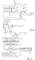
- la figure 1, déjà analysée, représente schématiquement un démarreur comportant un dispositif de commande électronisé ;
- la figure 2, qui illustre le principe mis en oeuvre par l'invention, est un graphe sur lequel on a porté l'évolution de la tension de la borne d'alimentation à la tension de la batterie lors du processus de fermeture du contact de puissance du contacteur de la figure 1 ;
- la figure 3 est un organigramme qui illustre différentes étapes mises en oeuvre par le microprocesseur d'un dispositif conforme à la variante illustrée sur la figure 2.
- FIG. 1, already analyzed, schematically represents a starter comprising an electronic control device;
- FIG. 2, which illustrates the principle implemented by the invention, is a graph on which the evolution of the voltage of the supply terminal to the voltage of the battery has been plotted during the process of closing the contact of power of the contactor of FIG. 1;
- FIG. 3 is a flowchart which illustrates different steps implemented by the microprocessor of a device according to the variant illustrated in FIG. 2.
Le dispositif de commande est d'une structure générale analogue à celle illustrée sur la figure 1.The control device is of a structure general similar to that illustrated in Figure 1.
Sur son entrée qui est reliée à la borne B+ par
l'intermédiaire de l'interrupteur de clé de contact 6, le
microprocesseur 5 comporte un convertisseur analogique
numérique qui lui permet de mesurer la tension
d'alimentation sur la borne B+ lorsque l'interrupteur 6
est fermé.On its input which is connected to terminal B + by
through the
A la fermeture de l'interrupteur de contact 6, le
microprocesseur 5 lance le processus de démarrage en
fermant le transistor 4 (étape 15 sur l'organigramme de la
figure 3) et mesure la tension U2 en un temps T2 suivant
la fermeture de l'interrupteur 6 (étape 16).When the
Le temps T2 correspond à environ 10 à 20
millisecondes après le basculement du transistor 4 sur son
état passant.The time T 2 corresponds to approximately 10 to 20 milliseconds after the
L'évolution de la tension de la borne d'alimentation B+ dans le cas d'un démarrage normal est représentée sur la figure 2.Evolution of the terminal voltage B + in the case of a normal start-up is shown in figure 2.
A la fermeture de l'interrupteur 6, la tension fait une première chute qui correspond à l'intensité absorbée par le contacteur. Du fait des effets selfiques et de la variation de réluctance du contacteur due au déplacement du noyau plongeur, la tension ne reste pas constante. De légères ondulations apparaissent dans cette phase de fonctionnement.When switch 6 closes, the voltage makes a first fall which corresponds to the intensity absorbed by the contactor. Because of the selfic effects and the reluctance variation of the contactor due to displacement of the plunger, the tension does not remain constant. Slight ripples appear in this operating phase.
Lorsque le contacteur de puissance la se ferme, la surintensité au démarrage du moteur électrique produit une nouvelle chute de tension, en pratique toujours supérieure à 1 volt.When the power contactor closes, the overcurrent when starting the electric motor produces a new voltage drop, in practice always higher at 1 volt.
Par conséquent, à l'issue de l'étape 16 le
microprocesseur 5 vérifie l'apparition d'une chute de
tension significative au bout d'un temps Ts, Ts étant
généralement compris entre quelques dixièmes de secondes
et quelques secondes.Consequently, at the end of
Par exemple, le microprocesseur 5 vérifie si la
tension au temps T2 + Ts est ou non supérieure à U2 - dU,
où dU correspond à la chute de tension minimale attendue
(étape 17).For example, the
Si la nouvelle tension n'est pas inférieure à
U2 - dU, c'est-à-dire si la chute de tension n'est pas
apparue, le microprocesseur 5 bloque le transistor 4 pour
éviter sa détérioration (étape 18).If the new voltage is not less than U 2 - dU, that is to say if the voltage drop has not appeared, the
Si ce n'est pas le cas, le microprocesseur 5
poursuit le processus de démarrage (étape 19).If not, the
Le temps Ts est évidemment déterminé pour que
l'échauffement reste suffisamment faible pour que le
transistor 4 ne soit pas détérioré.The time T s is obviously determined so that the heating remains low enough so that the
Cette solution présente l'avantage de permettre de
ne pas détériorer le transistor de puissance 4 par un
fonctionnement prolongé en mode d'appel et ne nécessite
aucun composant supplémentaire pour réaliser cette
fonction.This solution has the advantage of allowing
do not damage the
Bien entendu, la solution qui vient d'être décrite pourrait s'appliquer de la même façon dans le cas où la commande de courant que réalise le transistor serait non pas de type tout ou rien mais progressive, le relais pouvant alors ne comporter qu'une seule bobine à la place d'une bobine d'appel et d'une bobine de maintien.Of course, the solution which has just been described could apply in the same way in case the current control that the transistor performs would be non not all or nothing but progressive, the relay can then have only one coil instead a call coil and a holding coil.
Par ailleurs, on notera que le dispositif de commande électronique de démarreurs illustré sur la figure 1 présente l'avantage d'être de type "autonome", c'est-à-dire de ne nécessiter aucune autre liaison électrique que celles utilisées par les démarreurs conventionnels non électronisés, à savoir un câble de commande permettant la liaison avec l'interrupteur de contact du véhicule, un câble d'alimentation de puissance relié à une borne d'alimentation, telle que la borne positive de la batterie, et un retour à la masse par la carcasse du démarreur.Furthermore, it will be noted that the device for electronic starter control illustrated in the figure 1 has the advantage of being of the "autonomous" type, that is to say not to require any other electrical connection than those used by conventional starters not electronic, namely a control cable allowing the connection with the vehicle's contact switch, a power supply cable connected to a terminal such as the positive terminal of the battery, and a return to ground by the carcass of the starter.
Claims (7)
- A device for controlling a contactor of a starter motor (D) of an automobile vehicle, said contactor (1) including a power contact (1a) controlling the supply of power to the electric motor (M) of the starter motor (D) and at least one coil (2, 3) controlling the movement of said contact (1a), said device including a unit (5) for controlling the starter motor (D) and a transistor (4) controlled by said unit (5) that controls the energizing of the coil(s) of the contactor (1), said control unit (5) including means for turning off the transistor if, between two successive times (T2 and T2 + Ts) following closing of the starter switch (6), the voltage drop (dU) at a point connected to receive the battery voltage (B+) is smaller than a given threshold.
- A device according to claim 1, characterized in that the control unit (5) is a microprocessor having an analogue-to-digital converter at its input connected to said point connected to receive the battery voltage and in that said microprocessor (5) determines the voltage drop (dU) between said successive times (T2 and T2 + Ts) following closing of the starter switch (6) and compares said voltage drop (dU) to said threshold.
- A device according to claim 1 or claim 2, characterized in that the microprocessor (5) controls the transistor (4) on an on/off basis.
- A device according to claim 1 or claim 2, characterized in that the microprocessor (5) controls the transistor (4) so as to energize the coil or coils of the contactor (1) progressively.
- A device for controlling the supply of power to an automobile vehicle starter motor (D) that includes a contactor (1) having a power contact (1a) that controls the supply of power to the electric motor (M) of the starter motor (D) and at least one coil (2, 3) that controls the movement of said contact (1a), the device being characterized in that it further includes a control device for the contactor (1) according to any preceding claim.
- A device according to claim 5, characterized in that the contactor (1) includes an actuator coil (2) and a latching coil (3).
- An automobile vehicle starter motor characterized in that it integrates a power supply control device according to claim 6.
Applications Claiming Priority (2)
| Application Number | Priority Date | Filing Date | Title |
|---|---|---|---|
| FR9703089A FR2760891B1 (en) | 1997-03-14 | 1997-03-14 | IMPROVEMENT IN DEVICES FOR CONTROLLING A MOTOR VEHICLE STARTER CONTACTOR |
| FR9703089 | 1997-03-14 |
Publications (2)
| Publication Number | Publication Date |
|---|---|
| EP0864744A1 EP0864744A1 (en) | 1998-09-16 |
| EP0864744B1 true EP0864744B1 (en) | 2002-12-11 |
Family
ID=9504778
Family Applications (1)
| Application Number | Title | Priority Date | Filing Date |
|---|---|---|---|
| EP98400553A Expired - Lifetime EP0864744B1 (en) | 1997-03-14 | 1998-03-10 | Improvements to devices for controlling a contactor for a vehicle starter motor |
Country Status (5)
| Country | Link |
|---|---|
| US (1) | US6011317A (en) |
| EP (1) | EP0864744B1 (en) |
| DE (1) | DE69809984T2 (en) |
| ES (1) | ES2189104T3 (en) |
| FR (1) | FR2760891B1 (en) |
Families Citing this family (3)
| Publication number | Priority date | Publication date | Assignee | Title |
|---|---|---|---|---|
| FR2839344B1 (en) | 2002-03-29 | 2005-12-02 | Valeo Equip Electr Moteur | ELECTRONIC CONTROL CIRCUIT FOR A MOTOR VEHICLE STARTER CONTACTOR EQUIPPED WITH CORRECTING MEANS IN THE EVENT OF NON-CLOSING OF THE POWER CONTACT |
| US7479711B2 (en) * | 2006-10-23 | 2009-01-20 | Ford Global Technologies, Llc | System and method for controlling cycling of a vehicle contactor |
| FR2987082B1 (en) * | 2012-02-17 | 2015-03-13 | Valeo Equip Electr Moteur | DEVICE FOR STARTING A THERMAL MOTOR OF A MOTOR VEHICLE EQUIPPED WITH A VOLTAGE MEASURING SYSTEM AND ASSOCIATED METHOD |
Citations (1)
| Publication number | Priority date | Publication date | Assignee | Title |
|---|---|---|---|---|
| US5345901A (en) * | 1993-07-26 | 1994-09-13 | Carrier Corporation | Starter motor protection system |
Family Cites Families (11)
| Publication number | Priority date | Publication date | Assignee | Title |
|---|---|---|---|---|
| US3893007A (en) * | 1973-07-06 | 1975-07-01 | Nippon Denso Co | Vehicle starter protective system |
| JPS5985377U (en) * | 1982-11-30 | 1984-06-09 | 三菱電機株式会社 | Engine starter protection device |
| JPH076469B2 (en) * | 1987-05-28 | 1995-01-30 | 三菱電機株式会社 | Automatic engine starting method and device |
| US4947051A (en) * | 1988-01-22 | 1990-08-07 | Mitsubishi Denki Kabushiki Kaisha | Starter protector for an engine |
| US4917411A (en) * | 1988-12-12 | 1990-04-17 | General Motors Corporation | Electronic starting motor control with low voltage protection |
| US4906857A (en) * | 1988-12-12 | 1990-03-06 | Kikusui Line Co., Ltd. | Electronic starting motor control having fail safe and overvoltage protection |
| DE4026232C2 (en) * | 1990-08-18 | 2003-09-04 | Bosch Gmbh Robert | Device for monitoring a speed sensor |
| US5459357A (en) * | 1991-08-08 | 1995-10-17 | Minks; Floyd M. | Engine operated switch for controlling operation of electrical load responsive to alternator voltage and/or battery voltage |
| US5287831A (en) * | 1991-08-15 | 1994-02-22 | Nartron Corporation | Vehicle starter and electrical system protection |
| DE19503537A1 (en) * | 1995-02-03 | 1996-08-08 | Bosch Gmbh Robert | Control circuit for motor vehicle IC engine starter motor |
| US5564375A (en) * | 1995-05-15 | 1996-10-15 | Wacker Corporation | Start circuit with anti-restart circuitry |
-
1997
- 1997-03-14 FR FR9703089A patent/FR2760891B1/en not_active Expired - Fee Related
-
1998
- 1998-03-10 ES ES98400553T patent/ES2189104T3/en not_active Expired - Lifetime
- 1998-03-10 EP EP98400553A patent/EP0864744B1/en not_active Expired - Lifetime
- 1998-03-10 DE DE69809984T patent/DE69809984T2/en not_active Expired - Lifetime
- 1998-03-13 US US09/042,169 patent/US6011317A/en not_active Expired - Lifetime
Patent Citations (1)
| Publication number | Priority date | Publication date | Assignee | Title |
|---|---|---|---|---|
| US5345901A (en) * | 1993-07-26 | 1994-09-13 | Carrier Corporation | Starter motor protection system |
Also Published As
| Publication number | Publication date |
|---|---|
| US6011317A (en) | 2000-01-04 |
| DE69809984T2 (en) | 2003-07-24 |
| FR2760891A1 (en) | 1998-09-18 |
| EP0864744A1 (en) | 1998-09-16 |
| ES2189104T3 (en) | 2003-07-01 |
| FR2760891B1 (en) | 1999-05-28 |
| DE69809984D1 (en) | 2003-01-23 |
Similar Documents
| Publication | Publication Date | Title |
|---|---|---|
| EP0911953B1 (en) | Control device for a vehicle starter | |
| FR2957386A1 (en) | SYSTEM FOR STARTING AN INTERNAL COMBUSTION ENGINE WITH OPERATION OF AN ELECTRIC MOTOR IN HIGH SPEED AND LOW SPEED MODES | |
| EP2385538A1 (en) | Electromagnetic contactor with a double contact and starter for a heat engine having the same | |
| EP0796992B1 (en) | Method and device for controlling a driving contactor for a vehicle starter motor | |
| EP1041277B1 (en) | Vehicle starter control device for preventing wear | |
| FR2960265A1 (en) | Heat engine starting device for vehicle, has short-circuit switch short-circuiting resistor and comprising normally closed contact that is switched to closed-circuit after contact of starter switch is switched to closed-circuit | |
| EP0814258B1 (en) | Power cut-off system for motor vehicle starter | |
| EP1058785B1 (en) | Device for controlling a motor vehicle starter | |
| EP0864744B1 (en) | Improvements to devices for controlling a contactor for a vehicle starter motor | |
| EP0833051B1 (en) | Method and device for actioning the interruption of a vehicle engine starter motor | |
| EP0864745B1 (en) | Device for controlling a contactor for a vehicle starter motor | |
| EP0921305B1 (en) | Method and device for the alimentation control of a bobbin for a contactor of an automotive vehicle starter | |
| FR2870986A1 (en) | RELAY CONTROL DEVICE FOR DIRECT CURRENT ELECTRICAL APPARATUS | |
| FR2792416A1 (en) | METHOD FOR CONTROLLING THE LIMIT SWITCH OF A MOBILE MEMBER AND DEVICE FOR IMPLEMENTING IT | |
| EP0921306B1 (en) | Control device for an automotive vehicle starter | |
| WO2003083288A1 (en) | Electronic control circuit for a starting switch of a motor vehicle | |
| EP1462645B1 (en) | Control device of an engine starter of a vehicle | |
| FR2802364A1 (en) | METHOD AND DEVICE FOR CONTROLLING THE POWER SUPPLY OF A ROTOR WINDING OF AN ELECTRIC MACHINE SUCH AS AN ALTERNATOR OR ALTERNATOR-STARTER OF A VEHICLE, IN PARTICULAR A MOTOR VEHICLE | |
| FR2802363A1 (en) | Improved rotor winding current control for an automobile alternator, starter or alternator/starter has provision for short-term operation with over-excitation | |
| FR2843782A1 (en) | STARTING SYSTEM WITH SEPARATE STARTER CONTROL DEVICE | |
| EP1041276A1 (en) | Vehicle starter with reduced wear | |
| FR2896346A1 (en) | Circuit breaker assembly for vehicle`s storage battery, has movable contact unit displaced to close or open electric contact between terminals of assembly, and electronic circuit with microprocessor for managing displacement of contact unit | |
| FR2841941A1 (en) | Starter motor for motor vehicle has output shaft with solenoid actuated throw out clutch | |
| FR2860338A1 (en) | Device for controlling power supply to electric window motor of vehicle, has electromechanical relay and power transistor connected in series, with transistor being blocked before switching on interrupter | |
| FR2489425A1 (en) | Starter for IC engine driving heat pump compressor - uses conventional automotive starter motor supplied from AC mains through step-down transformer and rectifier |
Legal Events
| Date | Code | Title | Description |
|---|---|---|---|
| PUAI | Public reference made under article 153(3) epc to a published international application that has entered the european phase |
Free format text: ORIGINAL CODE: 0009012 |
|
| AK | Designated contracting states |
Kind code of ref document: A1 Designated state(s): DE ES GB IT |
|
| AX | Request for extension of the european patent |
Free format text: AL;LT;LV;MK;RO;SI |
|
| 17P | Request for examination filed |
Effective date: 19990301 |
|
| AKX | Designation fees paid |
Free format text: DE ES GB IT |
|
| RBV | Designated contracting states (corrected) |
Designated state(s): DE ES GB IT |
|
| GRAG | Despatch of communication of intention to grant |
Free format text: ORIGINAL CODE: EPIDOS AGRA |
|
| 17Q | First examination report despatched |
Effective date: 20020314 |
|
| GRAG | Despatch of communication of intention to grant |
Free format text: ORIGINAL CODE: EPIDOS AGRA |
|
| GRAH | Despatch of communication of intention to grant a patent |
Free format text: ORIGINAL CODE: EPIDOS IGRA |
|
| GRAH | Despatch of communication of intention to grant a patent |
Free format text: ORIGINAL CODE: EPIDOS IGRA |
|
| GRAA | (expected) grant |
Free format text: ORIGINAL CODE: 0009210 |
|
| AK | Designated contracting states |
Kind code of ref document: B1 Designated state(s): DE ES GB IT |
|
| REG | Reference to a national code |
Ref country code: GB Ref legal event code: FG4D Free format text: NOT ENGLISH |
|
| REF | Corresponds to: |
Ref document number: 69809984 Country of ref document: DE Date of ref document: 20030123 |
|
| PGFP | Annual fee paid to national office [announced via postgrant information from national office to epo] |
Ref country code: GB Payment date: 20030304 Year of fee payment: 6 |
|
| GBT | Gb: translation of ep patent filed (gb section 77(6)(a)/1977) |
Effective date: 20030219 |
|
| PGFP | Annual fee paid to national office [announced via postgrant information from national office to epo] |
Ref country code: ES Payment date: 20030314 Year of fee payment: 6 |
|
| REG | Reference to a national code |
Ref country code: ES Ref legal event code: FG2A Ref document number: 2189104 Country of ref document: ES Kind code of ref document: T3 |
|
| PLBE | No opposition filed within time limit |
Free format text: ORIGINAL CODE: 0009261 |
|
| STAA | Information on the status of an ep patent application or granted ep patent |
Free format text: STATUS: NO OPPOSITION FILED WITHIN TIME LIMIT |
|
| 26N | No opposition filed |
Effective date: 20030912 |
|
| PG25 | Lapsed in a contracting state [announced via postgrant information from national office to epo] |
Ref country code: GB Free format text: LAPSE BECAUSE OF NON-PAYMENT OF DUE FEES Effective date: 20040310 |
|
| PG25 | Lapsed in a contracting state [announced via postgrant information from national office to epo] |
Ref country code: ES Free format text: LAPSE BECAUSE OF NON-PAYMENT OF DUE FEES Effective date: 20040311 |
|
| GBPC | Gb: european patent ceased through non-payment of renewal fee |
Effective date: 20040310 |
|
| REG | Reference to a national code |
Ref country code: ES Ref legal event code: FD2A Effective date: 20040311 |
|
| PGFP | Annual fee paid to national office [announced via postgrant information from national office to epo] |
Ref country code: IT Payment date: 20080328 Year of fee payment: 11 |
|
| PG25 | Lapsed in a contracting state [announced via postgrant information from national office to epo] |
Ref country code: IT Free format text: LAPSE BECAUSE OF NON-PAYMENT OF DUE FEES Effective date: 20090310 |
|
| PGFP | Annual fee paid to national office [announced via postgrant information from national office to epo] |
Ref country code: DE Payment date: 20110310 Year of fee payment: 14 |
|
| REG | Reference to a national code |
Ref country code: DE Ref legal event code: R119 Ref document number: 69809984 Country of ref document: DE Effective date: 20121002 |
|
| PG25 | Lapsed in a contracting state [announced via postgrant information from national office to epo] |
Ref country code: DE Free format text: LAPSE BECAUSE OF NON-PAYMENT OF DUE FEES Effective date: 20121002 |