EP0864411A1 - Mould for manufacturing disc-like objects - Google Patents
Mould for manufacturing disc-like objects Download PDFInfo
- Publication number
- EP0864411A1 EP0864411A1 EP98200734A EP98200734A EP0864411A1 EP 0864411 A1 EP0864411 A1 EP 0864411A1 EP 98200734 A EP98200734 A EP 98200734A EP 98200734 A EP98200734 A EP 98200734A EP 0864411 A1 EP0864411 A1 EP 0864411A1
- Authority
- EP
- European Patent Office
- Prior art keywords
- mould
- tempering
- disc
- mould cavity
- cavity
- Prior art date
- Legal status (The legal status is an assumption and is not a legal conclusion. Google has not performed a legal analysis and makes no representation as to the accuracy of the status listed.)
- Granted
Links
- 238000004519 manufacturing process Methods 0.000 title claims abstract description 15
- 238000005496 tempering Methods 0.000 claims abstract description 48
- 238000002347 injection Methods 0.000 claims abstract description 34
- 239000007924 injection Substances 0.000 claims abstract description 34
- 239000004033 plastic Substances 0.000 claims abstract description 22
- 229920003023 plastic Polymers 0.000 claims abstract description 22
- 230000002093 peripheral effect Effects 0.000 claims description 17
- 239000000956 alloy Substances 0.000 claims description 5
- 229910045601 alloy Inorganic materials 0.000 claims description 5
- 239000006163 transport media Substances 0.000 claims description 4
- 229910000906 Bronze Inorganic materials 0.000 claims description 3
- 229910000831 Steel Inorganic materials 0.000 claims description 3
- 239000010974 bronze Substances 0.000 claims description 3
- 239000004020 conductor Substances 0.000 claims description 3
- KUNSUQLRTQLHQQ-UHFFFAOYSA-N copper tin Chemical compound [Cu].[Sn] KUNSUQLRTQLHQQ-UHFFFAOYSA-N 0.000 claims description 3
- 239000010959 steel Substances 0.000 claims description 3
- VYZAMTAEIAYCRO-UHFFFAOYSA-N Chromium Chemical compound [Cr] VYZAMTAEIAYCRO-UHFFFAOYSA-N 0.000 claims description 2
- NRTOMJZYCJJWKI-UHFFFAOYSA-N Titanium nitride Chemical compound [Ti]#N NRTOMJZYCJJWKI-UHFFFAOYSA-N 0.000 claims description 2
- DMFGNRRURHSENX-UHFFFAOYSA-N beryllium copper Chemical compound [Be].[Cu] DMFGNRRURHSENX-UHFFFAOYSA-N 0.000 claims description 2
- 239000011248 coating agent Substances 0.000 claims description 2
- 238000000576 coating method Methods 0.000 claims description 2
- XLYOFNOQVPJJNP-UHFFFAOYSA-N water Substances O XLYOFNOQVPJJNP-UHFFFAOYSA-N 0.000 claims description 2
- 238000001816 cooling Methods 0.000 description 32
- 238000013022 venting Methods 0.000 description 6
- 230000007423 decrease Effects 0.000 description 5
- 239000000969 carrier Substances 0.000 description 4
- 238000001746 injection moulding Methods 0.000 description 4
- 238000000034 method Methods 0.000 description 4
- 239000004417 polycarbonate Substances 0.000 description 4
- 229920000515 polycarbonate Polymers 0.000 description 4
- 238000003825 pressing Methods 0.000 description 4
- 238000009792 diffusion process Methods 0.000 description 3
- 230000006872 improvement Effects 0.000 description 3
- 239000000463 material Substances 0.000 description 3
- 230000003287 optical effect Effects 0.000 description 3
- 239000000758 substrate Substances 0.000 description 3
- PXHVJJICTQNCMI-UHFFFAOYSA-N Nickel Chemical compound [Ni] PXHVJJICTQNCMI-UHFFFAOYSA-N 0.000 description 2
- 230000008901 benefit Effects 0.000 description 2
- 238000005485 electric heating Methods 0.000 description 2
- 239000002609 medium Substances 0.000 description 2
- 230000008569 process Effects 0.000 description 2
- 230000009471 action Effects 0.000 description 1
- 230000008859 change Effects 0.000 description 1
- 229910052804 chromium Inorganic materials 0.000 description 1
- 239000011651 chromium Substances 0.000 description 1
- 230000006835 compression Effects 0.000 description 1
- 238000007906 compression Methods 0.000 description 1
- 239000000356 contaminant Substances 0.000 description 1
- 238000013461 design Methods 0.000 description 1
- 238000002474 experimental method Methods 0.000 description 1
- 238000007710 freezing Methods 0.000 description 1
- 230000008014 freezing Effects 0.000 description 1
- 238000005259 measurement Methods 0.000 description 1
- 229910052759 nickel Inorganic materials 0.000 description 1
- 230000005855 radiation Effects 0.000 description 1
- 230000010076 replication Effects 0.000 description 1
- 238000003860 storage Methods 0.000 description 1
Images


Classifications
-
- B—PERFORMING OPERATIONS; TRANSPORTING
- B29—WORKING OF PLASTICS; WORKING OF SUBSTANCES IN A PLASTIC STATE IN GENERAL
- B29C—SHAPING OR JOINING OF PLASTICS; SHAPING OF MATERIAL IN A PLASTIC STATE, NOT OTHERWISE PROVIDED FOR; AFTER-TREATMENT OF THE SHAPED PRODUCTS, e.g. REPAIRING
- B29C45/00—Injection moulding, i.e. forcing the required volume of moulding material through a nozzle into a closed mould; Apparatus therefor
- B29C45/17—Component parts, details or accessories; Auxiliary operations
- B29C45/26—Moulds
- B29C45/263—Moulds with mould wall parts provided with fine grooves or impressions, e.g. for record discs
- B29C45/2642—Heating or cooling means therefor
- B29C2045/2644—Heating or cooling means therefor for the outer peripheral ring
-
- Y—GENERAL TAGGING OF NEW TECHNOLOGICAL DEVELOPMENTS; GENERAL TAGGING OF CROSS-SECTIONAL TECHNOLOGIES SPANNING OVER SEVERAL SECTIONS OF THE IPC; TECHNICAL SUBJECTS COVERED BY FORMER USPC CROSS-REFERENCE ART COLLECTIONS [XRACs] AND DIGESTS
- Y10—TECHNICAL SUBJECTS COVERED BY FORMER USPC
- Y10S—TECHNICAL SUBJECTS COVERED BY FORMER USPC CROSS-REFERENCE ART COLLECTIONS [XRACs] AND DIGESTS
- Y10S425/00—Plastic article or earthenware shaping or treating: apparatus
- Y10S425/81—Sound record
Definitions
- the invention lies in the field of manufacturing disc-like plastic objects by means of a mould.
- the manufacture of disc-like objects by means of a mould is known.
- Diverse known techniques are, among others, injection moulding, injection pressing, injection compression and coining.
- the invention is applicable to all of these as well as other suitable techniques.
- the invention relates to a mould for manufacturing disc-like objects, which mould comprises:
- Such a mould is known generally and in many embodiments.
- the disc-like objects are in particular transparent information carriers such as CDs and DVDs.
- information carriers For a correct scanning of the digital information arranged thereon, such information carriers must comply with very specific technical requirements.
- technical requirements also include properties relating to birefringence, which must meet a required standard within close tolerances and must generally be as low as possible.
- the birefringence is an optical measurement value for internal material stresses. These internal stresses are introduced during manufacture by injection moulding or injection pressing of polycarbonate substrates. They are caused by shrinkage, flow lines and/or inclusions of air or other contaminants. The stresses result in the light of the laser being additionally diffused during scanning, whereby phase differences occur when a substrate is scanned. This diffusion of light rays results in a decrease in the effective intensity of the laser beam. Thereafter, light rays are also deflected and diffusion occurs when radiation transfers from the one medium to another medium with a different density.
- the wavelength of a scanning laser is roughly 780 nm in air and about 500 nm in polycarbonate.
- the light diffusion index is 1.55.
- this may vary by a maximum of 20% from the given value and may thus amount to a maximum of 100 nm.
- a larger variation will certainly result in problems. It is remarked here that in the case of production processes for mass-produced articles such as those under consideration, it must be ensured under all circumstances that the relevant norm is achieved, even in the most unfavourable conditions. It is therefore desirable to design a mould such that the birefringence is thus as low as possible in all conditions and is nominally considerably lower than the stated tolerance limits.
- the birefringence is measured in terms of phase differences and decrease in light intensity between a ⁇ -component and the ⁇ -component of polarized light.
- the birefringence is expressed in nanometres (nm).
- an optionally replaceable wall of the mould cavity is provided with a negative impression of information to be arranged on the disc-like object.
- Such information must be transferred with very great reliability and accuracy onto the disc-like object.
- a main purpose of the invention is to improve the quality of a manufactured disc-like object while reducing the cycle time.
- This operating window is understood to mean the total range in which combinations of parameter values are possible wherein the set requirements can be fulfilled.
- the invention provides a mould of the type stated in the preamble which has the feature that at least one of the two mould parts is provided with first tempering means which are active substantially only in the middle zone of the mould cavity for tempering the inflowing plastic during the inflow thereof via the pressure line and thus the filling of the mould cavity.
- an injection mould of which the so-called mirrors, i.e. the substantially plane walls of the mould cavity, the so-called punch and the injection conduit or injection bush are provided with cooling means.
- cooling means have not been found effective in realizing the above stated objectives of the invention.
- this mould has the feature that the ratio of the diameters of the middle zone and of the mould cavity lies in the range of (0.30 ⁇ 0.15).
- the plasticized plastic flowing in via the central zone is subjected at that position to a temperature change.
- At the location of this central zone there is a flow in substantially radial direction in order to fill the mould cavity.
- a certain "freezing" of the relevant material takes place, whereby the effective passage of the material is limited.
- This passage therefore varies during the injection of plasticized plastic. The smaller the passage becomes, the higher the pressure required to keep constant the flow rate of the inflowing plastic. If the pressure were to be kept the same, the flow rate of the inflowing plastic would then decrease. It will be apparent that it is possible to experiment with the given parameters until the quality of an obtained disc-like object is as high as possible, or at least lies within for instance a required norm.
- the mould has the feature that at least one of the two mould parts is provided with second tempering means which are active substantially only in the peripheral zone of the mould cavity for tempering the inflowing plastic during the inflow thereof via the injection conduit and thus the filling of the mould cavity.
- This variant in particular can have the special feature that the second tempering means co-act directly with the peripheral wall surface of the mould cavity.
- the second tempering means can be arranged in a moving, so-called venting ring.
- the advantage of this second tempering means is that the index of refraction can hereby be influenced in terms of the birefringence of a transparent information carrier.
- the birefringence displays a sharp rise on the outside of the disc-like information carrier and, as will be described hereinbelow, reaches a critical limit of about ⁇ 50 nm.
- the second tempering means By embodying the second tempering means such that the relevant peripheral zone has a higher temperature than the substantially plane end walls of the mould cavity, the cooling flow front of the injected plastic in the mould cavity will contact the relatively hot wall parts of the peripheral zone and thereby obtain a different build-up of stress than in the case where this plastic comes into contact there with a relatively cold peripheral zone.
- the said internal build-up of stress has immediate consequences for the optical qualities of the obtained transparent information carrier.
- a high internal stress corresponds to a high birefringence.
- a further variant has the feature that an additional mould part is arranged round the mould part through which said injection conduit extends, which additional mould part is provided with third tempering means which are active substantially only in the region of the relevant end wall of the mould cavity round the injection conduit for tempering the plastic flowing into the mould cavity during the filling of the mould cavity.
- Said additional mould part is cooled by means of the third tempering means and thus forms a buffer between the cold injection conduit and the relatively hot adjacent plane wall of the mould cavity.
- mould part in question can act either for instance as punch or as positioning means.
- a specific embodiment is provided with mechanical positioning means for fixedly holding, by engaging on the end zone of a central hole, at least one disc-like insert bearing the negative impression of information to be arranged on the disc-like object, which positioning means are provided with fourth tempering means which are active in the region of the said engagement.
- the described positioning means comprise a central hub which has an annular hook which extends into the mould cavity and is dimensioned such that it can be placed in engaging co-action with the peripheral zone of a central hole in the disc-like insert.
- tempering means comprise channels for heat transport medium arranged in the mould parts. It is noted in this respect that other embodiments of the tempering means are also possible, for instance electric heating and/or cooling means. Electric heating means can comprise resistance elements, while cooling means can for instance comprise Peltier elements.
- a very inexpensive and effective embodiment has the special feature that the heat transport medium is water.
- the relevant surfaces of the mould cavity at least in the region of the tempering means, consist of a thermally conductive material, for instance steel, bronze or other alloy. What is important is that the tempering means can make thermal contact via the relevant wall surfaces with the plasticized plastic during forming of an object.
- a simple embodiment has the special feature that the channels are at least partially formed by embodying a relevant mould part, divided by the main plane of a channel, in two sub-parts, at least one of which sub-parts is provided with a groove corresponding with the channel and is covered with the other sub-part.
- the embodiment is recommended in which the active surfaces in the region of the tempering means comprise an alloy with high thermal conduction coefficient, for instance beryllium copper or Ampco.
- Yet another variant has the special feature that the active surfaces in the region of the tempering means are provided with a hard coating, for instance of chromium, titanium nitride or the like.
- the mould according to the invention can serve to manufacture transparent information carriers such as CDs, VLPs, DVDs and the like. It is often deemed impractical to arrange the negative impression of the information to be arranged on the information carrier directly onto a surface of the mould cavity.
- a disc-like insert or "stamper" on which the relevant negative information is arranged. Such an insert must be replaced after a certain time has elapsed, for instance after a number of production cycles or in order to manufacture a different type of information carrier.
- the invention also provides a mould which is characterized by positioning means for positioning and holding at least one disc-like insert bearing a negative impression of information to be arranged on the disc-like object, which positioning means comprise an at least partly cylindrical bush of thermally conductive material, for instance steel, bronze or other alloy, wherein the first tempering means also co-act with the positioning means.
- Said positioning means are per se known.
- a disc-like insert which is often made of nickel, is for instance held fast by a hook-like element which engages the relevant insert on the peripheral zone of a central hole present therein.
- the positioning means can serve for exact positioning as well as for releasable holding of said insert, which is generally designated a "stamper".
- This embodiment is of mechanical character.
- the positioning function can also be separated from the holding function. Exact positioning of the insert is possible by means of a protruding edge which co-acts with a central hole in the insert, while holding can take place by making use of magnetic forces, underpressure or other suitable means.
- moulds of various types exist.
- the stamper is held in position by mechanical means, magnetic means, underpressure or other suitable means against a wall of the mould cavity located opposite the outflow opening of the injection conduit.
- the stamper is held on the wall in which the injection conduit debouches. The invention has the same advantages for these different embodiments.
- the additional mould part can serve as punch or as positioning means.
- the mould according to the invention can have the further feature that the tempering means are adapted to hold the relevant active surfaces at a specific chosen temperature. Attention is drawn in this respect to the fact that the desired temperature can greatly depend on the location where the relevant tempering means are active. The desired temperature also depends on the cycle time.
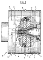
- Figures 1 and 2 show a mould 15 comprising two mould parts 16, 17.
- the central hub F comprises an annular hook with which stamper H is held.
- the central hook has an annular elevation which is ultimately delineated on the relevant zone of compact disc G.
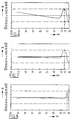
- Figure 3 shows the birefringence as a function of the radial position for a CD which is manufactured with a known mould provided with a cooled punch, a cooled injection bush and cooled mirrors.
- a recommended norm of ⁇ 50 nm is indicated with broken lines. The curve lies outside the given toleration limits particularly at about 57 and around 59 nm. It is further noticeable that in the range of about 30 mm - 50 mm the curve displays a fall in the amount of about 40 nm.
- the cooling by the first tempering means in the middle zone of the mould cavity causes a flatter progression of the curve.
- the total fall in the range of about 25 - 57 mm amounts to no more than about 15 nm.
- the maximum value of the birefringence will be reduced.
- the peak of the curve is also shifted outward close to the maximum radius of the information carrier. This is shown clearly in figure 5.
- the curve of figure 5 In the range between about 25 and 57 mm the curve of figure 5 generally shows a variation in the birefringence of no more than about 15 nm, while in the critical range 57 - 60 mm the curve also remains within the set toleration limits.
- the radial warpage decreases.
- the warpage can be compared with the general shape of a coolie hat. Due to the cooling of the peripheral zone the tangential warpage decreases. This corresponds with the general shape of a cowboy hat.
- Cycle time is understood to mean the total time duration required to manufacture one disc-like object with the mould according to the invention.
- FIGs 6, 7 and 8 show typical curves of the birefringence for the injection pressing process for comparison with the injection moulding process according to figures 3, 4 and 5.
- Figure 6 shows a typical curve without additional tempering
- figure 7 the curve where use is made of central tempering
- figure 8 a curve with both central tempering and peripheral tempering.
Landscapes
- Engineering & Computer Science (AREA)
- Manufacturing & Machinery (AREA)
- Mechanical Engineering (AREA)
- Moulds For Moulding Plastics Or The Like (AREA)
- Manufacturing Optical Record Carriers (AREA)
- Manufacture Of Macromolecular Shaped Articles (AREA)
- Moulding By Coating Moulds (AREA)
- Injection Moulding Of Plastics Or The Like (AREA)
Abstract
Description
- injection bush, punch: about 10°C - 30°C
- mirrors (plane surfaces of the mould cavity): about 40°C - 70°C
- peripheral zone: about 50°C - 100°C. The respective tempering means herefor specified in the claims can, subject to the wish to adjust specific temperatures, be adjustable either in combination or indeed individually.
- 1 inlet cooling channel punch;
- 2 outlet cooling channel punch;
- 3 inlet cooling channel injection bush;
- 4 outlet cooling channel injection bush;
- 5 outlet cooling channel front mirror;
- 6 inlet cooling channel front mirror;
- 7 inlet cooling channel venting ring;
- 8 outlet cooling channel venting ring;
- 9 cooling rear mirror;
- 10 inlet cooling channel central hub;
- 11 outlet cooling channel central hub;
- 12 inlet cooling channel punch;
- 13 outlet cooling channel punch;
- 14 suction line for holding stamper H via grooves;
- 15 mould;
- 16 first mould part;
- 17 second mould part.
Claims (13)
- Mould for manufacturing disc-like plastic objects, which mould comprises:at least two mould parts which are mutually movable between a closed position in which they bound a mould cavity, which mould cavity is connected to an injection conduit for admitting heated, plasticized plastic under pressure into said mould cavity, and an opened position in which a disc-like object can be removed; andremoving means for removing a central portion from a disc-like object to form a central hole present therein, which removing means comprise a cylindrical part which is movable in axial direction in the closed situation of the mould cavity,
characterized in thatat least one of the two mould parts is provided with first tempering means which are active substantially only in the middle zone of the mould cavity for tempering the inflowing plastic during the inflow thereof via the pressure line and thus the filling of the mould cavity. - Mould as claimed in claim 1,
characterized in thatthe ratio of the diameters of the middle zone and of the mould cavity lies in the range of (0.30 ± 0.15). - Mould as claimed in claim 1,
characterized in thatat least one of the two mould parts is provided with second tempering means which are active substantially only in the peripheral zone of the mould cavity for tempering the inflowing plastic during the inflow thereof via the injection conduit and thus the filling of the mould cavity. - Mould as claimed in claim 3,
characterized in thatthe second tempering means co-act directly with the peripheral wall surface of the mould cavity. - Mould as claimed in claim 1,
characterized in thatan additional mould part is arranged round the mould part through which said injection conduit extends, which additional mould part is provided with third tempering means which are active substantially only in the region of the relevant end wall of the mould cavity round the injection conduit for tempering the plastic flowing into the mould cavity during the filling of the mould cavity. - Mould as claimed in claim 1,
characterized by mechanical positioning means for fixedly holding, by engaging on the end zone of a central hole, at least one disc-like insert bearing the negative impression of information to be arranged on the disc-like object, which positioning means are provided with fourth tempering means which are active in the region of said engagement. - Mould as claimed in any of the foregoing claims,
characterized in thatthe tempering means comprise channels for heat transport medium arranged in the mould parts. - Mould as claimed in claim 7,
characterized in thatthe heat transport medium is water. - Mould as claimed in claim 7,
characterized in thatthe channels are at least partially formed by embodying a relevant mould part, divided by the main plane of a channel, in two sub-parts, at least one of which sub-parts is provided with a groove corresponding with the channel and is covered with the other sub-part. - Mould as claimed in claim 1,
characterized in thatthe active surfaces in the region of the tempering means comprise an alloy with high thermal conduction coefficient, for instance beryllium copper or Ampco. - Mould as claimed in claim 1,
characterized in thatthe active surfaces in the region of the tempering means are provided with a hard coating, for instance of chrome, titanium nitride or the like. - Mould as claimed in claim 1,
characterized bypositioning means for positioning and/or holding at least one disc-like insert bearing a negative impression of information to be arranged on the disc-like object, which positioning means comprise an at least partly cylindrical bush of thermally conductive material, for instance steel, bronze or other alloy, wherein the first tempering means also co-act with the positioning means. - Mould as claimed in claim 1,
characterized in thatthe tempering means are adapted to hold the relevant active surfaces at a specific chosen temperature.
Applications Claiming Priority (2)
| Application Number | Priority Date | Filing Date | Title |
|---|---|---|---|
| NL1005502A NL1005502C2 (en) | 1997-03-12 | 1997-03-12 | Die for manufacturing disc-shaped objects. |
| NL1005502 | 1997-03-12 |
Publications (2)
| Publication Number | Publication Date |
|---|---|
| EP0864411A1 true EP0864411A1 (en) | 1998-09-16 |
| EP0864411B1 EP0864411B1 (en) | 2004-06-02 |
Family
ID=19764580
Family Applications (1)
| Application Number | Title | Priority Date | Filing Date |
|---|---|---|---|
| EP98200734A Expired - Lifetime EP0864411B1 (en) | 1997-03-12 | 1998-03-09 | Mould for manufacturing disc-like objects |
Country Status (9)
| Country | Link |
|---|---|
| US (1) | US6322350B1 (en) |
| EP (1) | EP0864411B1 (en) |
| JP (1) | JP2939225B2 (en) |
| AT (1) | ATE268255T1 (en) |
| DE (1) | DE69824220T2 (en) |
| DK (1) | DK0864411T3 (en) |
| ES (1) | ES2218754T3 (en) |
| NL (1) | NL1005502C2 (en) |
| PT (1) | PT864411E (en) |
Cited By (6)
| Publication number | Priority date | Publication date | Assignee | Title |
|---|---|---|---|---|
| NL1016726C2 (en) * | 2000-11-29 | 2002-05-31 | Otb Group Bv | Injection molding method, has temperature of ring around first mold section regulated in order to control distance of gap between ring and mold section |
| EP1348531A1 (en) * | 2002-03-25 | 2003-10-01 | AWM Mold Tech AG | Injection mould for producing disc-shaped information carriers |
| EP1800823A1 (en) * | 2005-12-22 | 2007-06-27 | Thermal Cyclic Technologies TCTech i Stockholm AB | Injection mould with variable coolant flow rate, the corresponding method and injection mould with a venting ring |
| US7300609B2 (en) | 2003-09-08 | 2007-11-27 | Awm Mold Tech Ag | Injection-moulding tool for the production of information carriers in disc form |
| US7981350B2 (en) | 2005-12-22 | 2011-07-19 | Thermal Cyclic Technologies Tctech I Stockholm Ab | Method and apparatus for injection molding having an inductive coil heater |
| WO2016037640A1 (en) * | 2014-09-09 | 2016-03-17 | Qpharma Ab | An insertable mould assembly, a substrate and an injection moulding tool for the insertable mould assembly, method of using the insertable mould assembly and the injection moulding tool, objects obtained using same, and uses of the objects |
Families Citing this family (11)
| Publication number | Priority date | Publication date | Assignee | Title |
|---|---|---|---|---|
| US6467238B1 (en) * | 2000-06-15 | 2002-10-22 | Tetra Laval Holdings & Finance, Sa | Direct injection molded closure and method therefor |
| JP4053342B2 (en) * | 2002-04-19 | 2008-02-27 | 株式会社名機製作所 | Temperature control mechanism for disk mold |
| WO2004045822A1 (en) * | 2002-11-18 | 2004-06-03 | Sumitomo Heavy Industries, Ltd. | Molding die, molding method, disk substrate, and molding machine |
| TWI245699B (en) * | 2004-01-13 | 2005-12-21 | Asia Optical Co Inc | Shaping die with cooling runner |
| JP4028850B2 (en) * | 2004-02-04 | 2007-12-26 | 株式会社名機製作所 | Mold for molding disk substrate |
| US7802982B2 (en) * | 2005-05-09 | 2010-09-28 | Top Grade Molds, Ltd. | Grooved-surface air conduit for injection molds |
| ITMO20050224A1 (en) * | 2005-09-07 | 2007-03-08 | Sacmi | MOLDS FOR MOLDING OF PLASTIC ITEMS AND METHOD TO PRODUCE A MOLD ELEMENT |
| JP2007144880A (en) * | 2005-11-29 | 2007-06-14 | Seikoh Giken Co Ltd | Mold apparatus and mirror surfacing machine |
| DE102008036203B4 (en) | 2008-08-02 | 2012-09-20 | Optimal Media Production Gmbh | Injection molding tool for producing disk-shaped recording media |
| TWI404619B (en) * | 2009-04-07 | 2013-08-11 | 私立中原大學 | Gas mold surface heating system |
| KR20140117591A (en) | 2012-02-24 | 2014-10-07 | 더 프록터 앤드 갬블 캄파니 | Injection mold having a simplified cooling system |
Citations (12)
| Publication number | Priority date | Publication date | Assignee | Title |
|---|---|---|---|---|
| GB1209155A (en) * | 1966-11-29 | 1970-10-21 | Pathe Marconi Ind Music | Improvements in or relating to methods and apparatus for the manufacture of gramophone records |
| US4260360A (en) * | 1978-06-26 | 1981-04-07 | Mca Disco-Vision, Inc. | Method and means for replicating centrally apertured video disc records |
| JPS58224730A (en) * | 1982-06-25 | 1983-12-27 | Pioneer Electronic Corp | Temperature adjusting device of mold for injection molding |
| JPS6335320A (en) * | 1986-07-31 | 1988-02-16 | Idemitsu Petrochem Co Ltd | Injection molding equipment |
| EP0276897A2 (en) * | 1987-01-30 | 1988-08-03 | Canon Kabushiki Kaisha | Process for producing substrate for optical disk by annealing substrate with gradient double refraction distribution |
| JPS63295474A (en) * | 1987-05-27 | 1988-12-01 | Hitachi Metals Ltd | Mold for molding plastic disk |
| JPH01159221A (en) * | 1987-12-17 | 1989-06-22 | Tdk Corp | Molding device for optical disk |
| JPH01216807A (en) * | 1988-02-26 | 1989-08-30 | Toshiba Corp | Mold for disc |
| JPH05212766A (en) * | 1992-02-04 | 1993-08-24 | Mitsubishi Plastics Ind Ltd | Mold for molding disk substrate |
| JPH05278088A (en) * | 1992-03-04 | 1993-10-26 | Sharp Corp | Mold for molding optical disc |
| JPH068297A (en) * | 1991-07-19 | 1994-01-18 | Meiki Co Ltd | Injection mold for molding disc product |
| WO1994020288A1 (en) * | 1993-03-05 | 1994-09-15 | Ict Axxicon B.V. | Mould for manufacturing disc-shaped information carriers |
Family Cites Families (4)
| Publication number | Priority date | Publication date | Assignee | Title |
|---|---|---|---|---|
| GB1509362A (en) * | 1977-01-17 | 1978-05-04 | Emi Electrola Gmbh | Disc record press |
| JP2845394B2 (en) * | 1993-12-22 | 1999-01-13 | 住友重機械プラスチックマシナリー株式会社 | Injection mold |
| JP2839470B2 (en) * | 1995-12-12 | 1998-12-16 | 株式会社精工技研 | Cooling device for optical disc substrate injection mold |
| JP2965908B2 (en) * | 1996-07-05 | 1999-10-18 | 株式会社精工技研 | Mold device for optical disk molding provided with temperature-controlled liquid sealing means |
-
1997
- 1997-03-12 NL NL1005502A patent/NL1005502C2/en not_active IP Right Cessation
-
1998
- 1998-03-09 PT PT98200734T patent/PT864411E/en unknown
- 1998-03-09 DK DK98200734T patent/DK0864411T3/en active
- 1998-03-09 DE DE69824220T patent/DE69824220T2/en not_active Expired - Fee Related
- 1998-03-09 EP EP98200734A patent/EP0864411B1/en not_active Expired - Lifetime
- 1998-03-09 ES ES98200734T patent/ES2218754T3/en not_active Expired - Lifetime
- 1998-03-09 AT AT98200734T patent/ATE268255T1/en not_active IP Right Cessation
- 1998-03-10 US US09/037,648 patent/US6322350B1/en not_active Expired - Fee Related
- 1998-03-12 JP JP10061108A patent/JP2939225B2/en not_active Expired - Fee Related
Patent Citations (12)
| Publication number | Priority date | Publication date | Assignee | Title |
|---|---|---|---|---|
| GB1209155A (en) * | 1966-11-29 | 1970-10-21 | Pathe Marconi Ind Music | Improvements in or relating to methods and apparatus for the manufacture of gramophone records |
| US4260360A (en) * | 1978-06-26 | 1981-04-07 | Mca Disco-Vision, Inc. | Method and means for replicating centrally apertured video disc records |
| JPS58224730A (en) * | 1982-06-25 | 1983-12-27 | Pioneer Electronic Corp | Temperature adjusting device of mold for injection molding |
| JPS6335320A (en) * | 1986-07-31 | 1988-02-16 | Idemitsu Petrochem Co Ltd | Injection molding equipment |
| EP0276897A2 (en) * | 1987-01-30 | 1988-08-03 | Canon Kabushiki Kaisha | Process for producing substrate for optical disk by annealing substrate with gradient double refraction distribution |
| JPS63295474A (en) * | 1987-05-27 | 1988-12-01 | Hitachi Metals Ltd | Mold for molding plastic disk |
| JPH01159221A (en) * | 1987-12-17 | 1989-06-22 | Tdk Corp | Molding device for optical disk |
| JPH01216807A (en) * | 1988-02-26 | 1989-08-30 | Toshiba Corp | Mold for disc |
| JPH068297A (en) * | 1991-07-19 | 1994-01-18 | Meiki Co Ltd | Injection mold for molding disc product |
| JPH05212766A (en) * | 1992-02-04 | 1993-08-24 | Mitsubishi Plastics Ind Ltd | Mold for molding disk substrate |
| JPH05278088A (en) * | 1992-03-04 | 1993-10-26 | Sharp Corp | Mold for molding optical disc |
| WO1994020288A1 (en) * | 1993-03-05 | 1994-09-15 | Ict Axxicon B.V. | Mould for manufacturing disc-shaped information carriers |
Non-Patent Citations (8)
| Title |
|---|
| PATENT ABSTRACTS OF JAPAN vol. 12, no. 247 (M - 717)<3094> 13 July 1988 (1988-07-13) * |
| PATENT ABSTRACTS OF JAPAN vol. 13, no. 124 (C - 580)<3472> 27 March 1989 (1989-03-27) * |
| PATENT ABSTRACTS OF JAPAN vol. 13, no. 420 (M - 872)<3768> 19 September 1989 (1989-09-19) * |
| PATENT ABSTRACTS OF JAPAN vol. 13, no. 528 (M - 898)<3876> 24 November 1989 (1989-11-24) * |
| PATENT ABSTRACTS OF JAPAN vol. 17, no. 651 (M - 1519) 3 December 1993 (1993-12-03) * |
| PATENT ABSTRACTS OF JAPAN vol. 18, no. 206 (M - 1591) 12 April 1994 (1994-04-12) * |
| PATENT ABSTRACTS OF JAPAN vol. 18, no. 54 (M - 1549) 27 January 1994 (1994-01-27) * |
| PATENT ABSTRACTS OF JAPAN vol. 8, no. 80 (M - 289)<1517> 12 April 1984 (1984-04-12) * |
Cited By (6)
| Publication number | Priority date | Publication date | Assignee | Title |
|---|---|---|---|---|
| NL1016726C2 (en) * | 2000-11-29 | 2002-05-31 | Otb Group Bv | Injection molding method, has temperature of ring around first mold section regulated in order to control distance of gap between ring and mold section |
| EP1348531A1 (en) * | 2002-03-25 | 2003-10-01 | AWM Mold Tech AG | Injection mould for producing disc-shaped information carriers |
| US7300609B2 (en) | 2003-09-08 | 2007-11-27 | Awm Mold Tech Ag | Injection-moulding tool for the production of information carriers in disc form |
| EP1800823A1 (en) * | 2005-12-22 | 2007-06-27 | Thermal Cyclic Technologies TCTech i Stockholm AB | Injection mould with variable coolant flow rate, the corresponding method and injection mould with a venting ring |
| US7981350B2 (en) | 2005-12-22 | 2011-07-19 | Thermal Cyclic Technologies Tctech I Stockholm Ab | Method and apparatus for injection molding having an inductive coil heater |
| WO2016037640A1 (en) * | 2014-09-09 | 2016-03-17 | Qpharma Ab | An insertable mould assembly, a substrate and an injection moulding tool for the insertable mould assembly, method of using the insertable mould assembly and the injection moulding tool, objects obtained using same, and uses of the objects |
Also Published As
| Publication number | Publication date |
|---|---|
| DE69824220T2 (en) | 2005-07-14 |
| JP2939225B2 (en) | 1999-08-25 |
| NL1005502C2 (en) | 1998-09-15 |
| DK0864411T3 (en) | 2004-10-11 |
| PT864411E (en) | 2004-09-30 |
| JPH10291237A (en) | 1998-11-04 |
| ES2218754T3 (en) | 2004-11-16 |
| US6322350B1 (en) | 2001-11-27 |
| EP0864411B1 (en) | 2004-06-02 |
| DE69824220D1 (en) | 2004-07-08 |
| ATE268255T1 (en) | 2004-06-15 |
Similar Documents
| Publication | Publication Date | Title |
|---|---|---|
| EP0864411B1 (en) | Mould for manufacturing disc-like objects | |
| US5002706A (en) | Injection molding process of a plastic substrate for an optical disk | |
| US5683630A (en) | Process for making optical disk substrates | |
| EP1192034B1 (en) | Method of forming an optical disk with reduced edge wedge | |
| JP4263008B2 (en) | INJECTION MOLDING APPARATUS FOR MANUFACTURING DISK SUBSTRATE AND METHOD FOR MANUFACTURING DISK SUBSTRATE | |
| JP5650641B2 (en) | Disc substrate molding apparatus, disc substrate molding method, and disc substrate molding die | |
| US20030194464A1 (en) | Mold for molding the substrate of an optical disk | |
| US20060220268A1 (en) | Method and mold for injection molding optical article with increased surface accuracy | |
| JP4081240B2 (en) | Injection molding apparatus for manufacturing disc-type information recording carrier | |
| EP1136223A2 (en) | Mold for injection molding of disc substrate | |
| JP3871815B2 (en) | Mold for optical disc | |
| JP2000263615A (en) | Mold for optical information recording medium substrate | |
| EP0846542A1 (en) | Method of and apparatus for molding with multiple temperature adjusting channels | |
| JP2004195756A (en) | Mold for optical disk substrate | |
| JP2006327147A (en) | Forming method of plastic lens and plastic lens | |
| JP2002127193A (en) | Optical disk substrate molding die, and molding method for optical disk substrate | |
| JP2004291341A (en) | Mold for optical element, method for molding optical element, and optical element | |
| JPH07323486A (en) | Method for manufacturing plastic molded products | |
| JP2555149B2 (en) | Optical disc substrate and its molding die | |
| JP2001243656A (en) | Optical disk and injection mold for disk | |
| JP2002347093A (en) | Mold for injection molding | |
| JPH0531777A (en) | Optical disk substrate molding method | |
| JPH0757306A (en) | Mold for optical disk molding | |
| JP2007280582A (en) | Metallic mold for manufacturing optical recording medium substrate | |
| JP2003200460A (en) | Optical disk mold |
Legal Events
| Date | Code | Title | Description |
|---|---|---|---|
| PUAI | Public reference made under article 153(3) epc to a published international application that has entered the european phase |
Free format text: ORIGINAL CODE: 0009012 |
|
| AK | Designated contracting states |
Kind code of ref document: A1 Designated state(s): AT BE CH DE DK ES FI FR GB GR IE IT LI LU MC NL PT SE |
|
| AX | Request for extension of the european patent |
Free format text: AL;LT;LV;MK;RO;SI |
|
| 17P | Request for examination filed |
Effective date: 19990309 |
|
| AKX | Designation fees paid |
Free format text: AT BE CH DE DK ES FI FR GB GR IE IT LI LU MC NL PT SE |
|
| RBV | Designated contracting states (corrected) |
Designated state(s): AT BE CH DE DK ES FI FR GB GR IE IT LI LU MC NL PT SE |
|
| 17Q | First examination report despatched |
Effective date: 20000619 |
|
| GRAH | Despatch of communication of intention to grant a patent |
Free format text: ORIGINAL CODE: EPIDOS IGRA |
|
| GRAS | Grant fee paid |
Free format text: ORIGINAL CODE: EPIDOSNIGR3 |
|
| GRAA | (expected) grant |
Free format text: ORIGINAL CODE: 0009210 |
|
| AK | Designated contracting states |
Kind code of ref document: B1 Designated state(s): AT BE CH DE DK ES FI FR GB GR IE IT LI LU MC NL PT SE |
|
| REG | Reference to a national code |
Ref country code: GB Ref legal event code: FG4D |
|
| REG | Reference to a national code |
Ref country code: CH Ref legal event code: NV Representative=s name: ARNOLD & SIEDSMA AG Ref country code: CH Ref legal event code: EP |
|
| REF | Corresponds to: |
Ref document number: 69824220 Country of ref document: DE Date of ref document: 20040708 Kind code of ref document: P |
|
| REG | Reference to a national code |
Ref country code: GR Ref legal event code: EP Ref document number: 20040402067 Country of ref document: GR |
|
| REG | Reference to a national code |
Ref country code: IE Ref legal event code: FG4D |
|
| REG | Reference to a national code |
Ref country code: SE Ref legal event code: TRGR |
|
| REG | Reference to a national code |
Ref country code: PT Ref legal event code: SC4A Free format text: AVAILABILITY OF NATIONAL TRANSLATION Effective date: 20040730 |
|
| REG | Reference to a national code |
Ref country code: DK Ref legal event code: T3 |
|
| REG | Reference to a national code |
Ref country code: ES Ref legal event code: FG2A Ref document number: 2218754 Country of ref document: ES Kind code of ref document: T3 |
|
| ET | Fr: translation filed | ||
| PLBE | No opposition filed within time limit |
Free format text: ORIGINAL CODE: 0009261 |
|
| STAA | Information on the status of an ep patent application or granted ep patent |
Free format text: STATUS: NO OPPOSITION FILED WITHIN TIME LIMIT |
|
| 26N | No opposition filed |
Effective date: 20050303 |
|
| PGFP | Annual fee paid to national office [announced via postgrant information from national office to epo] |
Ref country code: DK Payment date: 20080331 Year of fee payment: 11 |
|
| PGFP | Annual fee paid to national office [announced via postgrant information from national office to epo] |
Ref country code: NL Payment date: 20080331 Year of fee payment: 11 Ref country code: MC Payment date: 20080331 Year of fee payment: 11 Ref country code: LU Payment date: 20080326 Year of fee payment: 11 Ref country code: IT Payment date: 20080328 Year of fee payment: 11 Ref country code: GB Payment date: 20080331 Year of fee payment: 11 Ref country code: FI Payment date: 20080327 Year of fee payment: 11 |
|
| PGFP | Annual fee paid to national office [announced via postgrant information from national office to epo] |
Ref country code: AT Payment date: 20080327 Year of fee payment: 11 |
|
| PGFP | Annual fee paid to national office [announced via postgrant information from national office to epo] |
Ref country code: ES Payment date: 20080331 Year of fee payment: 11 Ref country code: DE Payment date: 20080331 Year of fee payment: 11 Ref country code: CH Payment date: 20080328 Year of fee payment: 11 |
|
| PGFP | Annual fee paid to national office [announced via postgrant information from national office to epo] |
Ref country code: BE Payment date: 20080401 Year of fee payment: 11 |
|
| PGFP | Annual fee paid to national office [announced via postgrant information from national office to epo] |
Ref country code: SE Payment date: 20080331 Year of fee payment: 11 Ref country code: PT Payment date: 20080828 Year of fee payment: 11 |
|
| PGFP | Annual fee paid to national office [announced via postgrant information from national office to epo] |
Ref country code: IE Payment date: 20080829 Year of fee payment: 11 Ref country code: FR Payment date: 20080326 Year of fee payment: 11 |
|
| PGFP | Annual fee paid to national office [announced via postgrant information from national office to epo] |
Ref country code: GR Payment date: 20080328 Year of fee payment: 11 |
|
| REG | Reference to a national code |
Ref country code: PT Ref legal event code: MM4A Free format text: LAPSE DUE TO NON-PAYMENT OF FEES Effective date: 20090909 |
|
| BERE | Be: lapsed |
Owner name: *AXXICON MOULDS EINDHOVEN B.V. Effective date: 20090331 |
|
| PG25 | Lapsed in a contracting state [announced via postgrant information from national office to epo] |
Ref country code: PT Free format text: LAPSE BECAUSE OF NON-PAYMENT OF DUE FEES Effective date: 20090909 Ref country code: MC Free format text: LAPSE BECAUSE OF NON-PAYMENT OF DUE FEES Effective date: 20090331 Ref country code: FI Free format text: LAPSE BECAUSE OF NON-PAYMENT OF DUE FEES Effective date: 20090309 Ref country code: AT Free format text: LAPSE BECAUSE OF NON-PAYMENT OF DUE FEES Effective date: 20090309 |
|
| REG | Reference to a national code |
Ref country code: CH Ref legal event code: PL |
|
| REG | Reference to a national code |
Ref country code: DK Ref legal event code: EBP |
|
| EUG | Se: european patent has lapsed | ||
| GBPC | Gb: european patent ceased through non-payment of renewal fee |
Effective date: 20090309 |
|
| NLV4 | Nl: lapsed or anulled due to non-payment of the annual fee |
Effective date: 20091001 |
|
| REG | Reference to a national code |
Ref country code: FR Ref legal event code: ST Effective date: 20091130 |
|
| REG | Reference to a national code |
Ref country code: IE Ref legal event code: MM4A |
|
| PG25 | Lapsed in a contracting state [announced via postgrant information from national office to epo] |
Ref country code: LI Free format text: LAPSE BECAUSE OF NON-PAYMENT OF DUE FEES Effective date: 20090331 Ref country code: IE Free format text: LAPSE BECAUSE OF NON-PAYMENT OF DUE FEES Effective date: 20090309 Ref country code: DE Free format text: LAPSE BECAUSE OF NON-PAYMENT OF DUE FEES Effective date: 20091001 Ref country code: CH Free format text: LAPSE BECAUSE OF NON-PAYMENT OF DUE FEES Effective date: 20090331 |
|
| PG25 | Lapsed in a contracting state [announced via postgrant information from national office to epo] |
Ref country code: NL Free format text: LAPSE BECAUSE OF NON-PAYMENT OF DUE FEES Effective date: 20091001 Ref country code: BE Free format text: LAPSE BECAUSE OF NON-PAYMENT OF DUE FEES Effective date: 20090331 |
|
| PG25 | Lapsed in a contracting state [announced via postgrant information from national office to epo] |
Ref country code: GB Free format text: LAPSE BECAUSE OF NON-PAYMENT OF DUE FEES Effective date: 20090309 Ref country code: FR Free format text: LAPSE BECAUSE OF NON-PAYMENT OF DUE FEES Effective date: 20091123 Ref country code: DK Free format text: LAPSE BECAUSE OF NON-PAYMENT OF DUE FEES Effective date: 20090331 |
|
| REG | Reference to a national code |
Ref country code: ES Ref legal event code: FD2A Effective date: 20090310 |
|
| PG25 | Lapsed in a contracting state [announced via postgrant information from national office to epo] |
Ref country code: GR Free format text: LAPSE BECAUSE OF NON-PAYMENT OF DUE FEES Effective date: 20091002 |
|
| PG25 | Lapsed in a contracting state [announced via postgrant information from national office to epo] |
Ref country code: ES Free format text: LAPSE BECAUSE OF NON-PAYMENT OF DUE FEES Effective date: 20090310 |
|
| PG25 | Lapsed in a contracting state [announced via postgrant information from national office to epo] |
Ref country code: IT Free format text: LAPSE BECAUSE OF NON-PAYMENT OF DUE FEES Effective date: 20090309 |
|
| PG25 | Lapsed in a contracting state [announced via postgrant information from national office to epo] |
Ref country code: LU Free format text: LAPSE BECAUSE OF NON-PAYMENT OF DUE FEES Effective date: 20090309 |
|
| PG25 | Lapsed in a contracting state [announced via postgrant information from national office to epo] |
Ref country code: SE Free format text: LAPSE BECAUSE OF NON-PAYMENT OF DUE FEES Effective date: 20090310 |