EP0863642A2 - Spektralformende Kode für PCM-Modems - Google Patents
Spektralformende Kode für PCM-ModemsInfo
- Publication number
- EP0863642A2 EP0863642A2 EP98103606A EP98103606A EP0863642A2 EP 0863642 A2 EP0863642 A2 EP 0863642A2 EP 98103606 A EP98103606 A EP 98103606A EP 98103606 A EP98103606 A EP 98103606A EP 0863642 A2 EP0863642 A2 EP 0863642A2
- Authority
- EP
- European Patent Office
- Prior art keywords
- data symbol
- sample value
- frequency
- sample
- transmitted signal
- Prior art date
- Legal status (The legal status is an assumption and is not a legal conclusion. Google has not performed a legal analysis and makes no representation as to the accuracy of the status listed.)
- Granted
Links
Images

Classifications
-
- H—ELECTRICITY
- H04—ELECTRIC COMMUNICATION TECHNIQUE
- H04L—TRANSMISSION OF DIGITAL INFORMATION, e.g. TELEGRAPHIC COMMUNICATION
- H04L25/00—Baseband systems
- H04L25/38—Synchronous or start-stop systems, e.g. for Baudot code
- H04L25/40—Transmitting circuits; Receiving circuits
- H04L25/49—Transmitting circuits; Receiving circuits using code conversion at the transmitter; using predistortion; using insertion of idle bits for obtaining a desired frequency spectrum; using three or more amplitude levels ; Baseband coding techniques specific to data transmission systems
- H04L25/4917—Transmitting circuits; Receiving circuits using code conversion at the transmitter; using predistortion; using insertion of idle bits for obtaining a desired frequency spectrum; using three or more amplitude levels ; Baseband coding techniques specific to data transmission systems using multilevel codes
- H04L25/4927—Transmitting circuits; Receiving circuits using code conversion at the transmitter; using predistortion; using insertion of idle bits for obtaining a desired frequency spectrum; using three or more amplitude levels ; Baseband coding techniques specific to data transmission systems using multilevel codes using levels matched to the quantisation levels of the channel
Definitions
- This invention relates to modems and to methods for encoding data for transmission through an analog communication system.
- Frequency responses in analog communication systems may limit the rate or quality of information transmissions.
- current telephone networks often employ transformers that have a frequency null at 0 Hz (i.e. for a DC signal component) and strong attenuation and non-linear distortion for signal components having frequencies less than about 100 Hz.
- signals having low frequency components that carry information are subject to information loss when transmitted through conventional telephone networks. Such losses can be a problem for modems that are connected through telephone networks.
- a proposed 56 kbit/s PCM modem generates a digital PCM (pulse code modulated) signal having a sampling frequency of 8 kHz.
- the PCM signal is sent in digital form to a telephone system central office where the PCM signal is converted to an analog or PAM (pulse amplitude modulated) signal for transmission on a local loop.
- PAM pulse amplitude modulated
- the PCM modem may use a one-to-one mapping from 7-bit data symbols to sample values in the PCM signal. For example, each sample value may represent and be equal to a 7-bit data symbol.
- the analog or PAM signal that results from digital-to-analog conversion of the PCM signal has a frequency spectrum that is essentially flat from 0 Hz up to a cut-off frequency of 4 kHz (i.e. half the sampling frequency). Accordingly, transformers in the telephone network can distort the information signal and degrade modem performance by attenuating the low frequency components relative to other components in the PAM signal.
- a communication systems may still distort the analog (or PAM) signal because the proposed mapping only compensates for variations in frequency response at low frequencies and other sources of variations in frequency response may be present.
- a digital-to-analog converter that converts a PCM signal to a PAM signal may include a low pass filter that eliminates high frequency components that result from aliasing and the local loop may have a frequency response that suppresses or distorts the high frequency components.
- a telephone network may distort desired high frequency components of an information signal.
- An adaptable transmission process is desired that reduce the problems of high and low frequency distortions.
- samples in PCM signal are processed to minimize both high and low frequency components in an analog or PAM signal.
- a process determines two indicators, a DC indicator indicating the magnitude of a DC component and a high-frequency indicator indicating the highest frequency component.
- the DC indicator can be, for example, a sum of the amplitudes of the PAM signal.
- the high frequency indicator can be for example, a sum of the amplitudes where the sign of every other sample is reversed.
- the processing of changes a sample value if an alternative sample value provides a lower weighted average of the absolute values of the two indicators.
- the alternative values can be provide by either of the above-described techniques.
- either some of the data symbols have two or more alternative representations as samples or the alternative is the negative of sample value and overhead bits are set to indicate any changes in samples used. For such processes, high frequency distortion in a telephone network affects information in the transmitted signal less.
- an initialization or handshake procedure measures the relative attenuation of the DC and high frequency components in a communication channel, and the weighting for the average of the DC and high-frequency components is selected according to the measured frequency response.
- One embodiment of the invention is a process for transmitting a series of data symbols. For each data symbol, a transmitter selects a sample value that represents the data symbol, and the sample value is converted to a voltage amplitude in a transmitted signal.
- the sample values may be, for example, in a pulse code modulated (PCM) signal from the transmitter that is later converted to a pulse amplitude modulated (PAM) signal.
- PCM pulse code modulated
- PAM pulse amplitude modulated
- the transmitter uses the sample values when determining indicators of the magnitudes of a first (e.g. DC) component and a second (e.g. highest) frequency component of the transmitted signal, and uses the indicators in the process of selecting sample values when alternatives are available.
- some data symbols may represented by two or more alternative sample values, so that any of the alternative sample values can be selected for the data symbol.
- the transmitter selects a sample value from the possible alternative sample values so that the first and second frequency components are minimized in the transmitted signal.
- the transmitter determines or updates first and second indicators by: determining a value S[Pi] representing the voltage amplitude generated by converting a sample value Pi representing the data symbol Di; adding to the first indicator a contribution proportional to value S[Pi] and adding to the second indicator a second contribution proportional to a product of (-1) i and S[Pi].
- a weighted average that is the sum of the absolute value of a product of a fraction x and the first indicator and the absolute value of a product of a fraction (1-x) and the second indicator.
- the fraction x may be fixed or selected according to the frequency response of the channel as measured during an initialization or handshake procedure. In a limiting case, fraction x is equal to zero or one, and only the high frequency component is reduced.
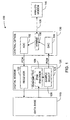
- Fig. 1 illustrates a digital modem connected to an analog modem through a telephone system.
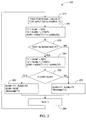
- Fig. 2 shows a flow diagram of a data transmission process in accordance with an embodiment of the invention.
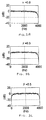
- Figs. 3A, 3B, 3C, 3D, and 3E illustrate possible frequency spectrums for transmission signals generated in accordance with embodiments of the invention.
- Fig. 1 illustrates a communication system 100 in which an embodiment of the invention may be employed.
- Communication system 100 includes a digital (or PCM) modem 120, a telephone system central office 130, and an analog modem 140.
- Modem 120 includes a transmitter 124 that generates a pulse code modulated (PCM) signal representing data from a data base 110.
- the PCM signal may be a bit stream that includes a series frames containing multi-bit sample values.
- the rate at which PCM sample values are transmitted is referred to herein as the sampling rate or frequency.
- a digital-to-analog converter (DAC) 134 converts the PCM signal into an analog or pulse amplitude modulated (PAM) signal transmitted over a local loop 138 to analog modem 140.
- DAC digital-to-analog converter
- DAC 134 implements a non-linear digital-to-analog conversion such as in well known ⁇ -law and A-law coding. Specifically, for a telephone network in the United States, DAC 134 performs a conversion that complies with a standard referred to as ITU G.711, for pulse code modulation of voice frequencies.
- a PCM encoder 126 in transmitter 124 receives data from data base 110, breaks the data into a series of multi-bit symbols, and maps the each symbol into a PCM sample value. For each PCM sample value from PCM encoder 126, a sample select circuit 128 in transmitter 124 selects and transmits either the PCM sample value or an alternative PCM sample value for the PCM sample from encoder 126.
- the set of alternatives available for selection depends on the encoding method employed.
- a mapping permits selection from two or more PCM sample values that represent the same data symbol for at least some of the data symbols.
- the alternative sample values are a function of the sample value from encoder 126, for example, an alternative for each sample may be the negative of the sample; and overhead bits are added to the PCM signal to indicated to a decoder in modem 140 whether the original sample from 126 or the alternative (i.e. negative) has been used.
- select circuit 128 maintains running totals SUM1 and SUM2 indicated in equations 1 and 2.
- SUM1 S[P0] + S[P1] + ...
- i is an index identifying the last PCM sample value
- P0 to Pi are the transmitted PCM sample values
- S[P] indicates the amplitude that DAC 134 generates from PCM sample value P.
- Value SUM1 indicates the magnitude of the low frequency components of the transmitted signal
- value SUM2 indicates the magnitude of the high frequency components which oscillate at a frequency that is about half the sampling frequency.
- Fig. 2 illustrates an exemplary process 200 used by transmitter 124 when generating the series of PCM sample values representing transmitted data.
- Process 200 generates one PCM sample value for each period of the sampling frequency.
- An index i and average SUM are initially zero, and an incoming bit stream is partitioned to extract data symbols Di and encode the each data symbol Di as a sample value Pi.
- the data symbols are 7-bit values
- the sampling frequency is 8 kHz
- PCM sample values Pi are 8-bit values to be converted to a PAM signal in accordance with the ITU G.711 standard.
- encoder 126 finds a PCM sample value Pi for data symbol Di.
- Value SUM is conditionally updated in step 220.
- the update in step 220 is conditional because value SUM is later changed in a step 260 if an alternative PCM signal Pi' value is selected.
- temporary values T1 and T2 are determined using sample value Pi according to equations 1 and 2 and the conversion function S[Pi].
- function S[Pi] is defined by the G.711 standard.
- Indicator SUM1 (T1) is a running total of amplitudes S[Pi] which may be positive or negative.
- addition and subtraction of amplitudes S[Pi] alternate at the sampling frequency, 8 kHz, so that the contribution of the repeated additions and subtractions indicate the magnitude of a highest frequency (4 kHz) signal component.
- select circuit 128 determines whether the sample value Pi is eligible for replacement by an alternative.
- Many alternatives for replacement are possible.
- an alternative sample value Pi' is the negative of sample value Pi.
- a bit in the data represented by the PCM signal can be set to indicate that a particular sample Pi does not have its usual interpretation but is the negative of the actual sample value Pi normally representing data symbol Di.
- Other method for selecting alternatives are known and usable by selection circuit 128.
- transmitter 124 selects and transmits PCM sample value Pi in step 270. If an alternative PCM sample value Pi, is to be considered, a value SUM' is determined according to equations 1 and 2 under the assumption that sample value Pi' is transmitted. A step 250 compares values SUM and SUM' to determine which is smaller. If value SUM is not greater than value SUM', process 200 transfers to step 270 to select and transmit PCM sample value Pi. If value SUM' is smaller than value SUM, process 200 transfers to step 260 to select and transmit PCM sample value Pi' and set value SUM equal to value SUM'. Once the PCM sample value Pi or Pi' providing the smallest value SUM is transmitted, step 280 increments index i, and transmitter 124 repeats process 200 for the next 7-bit data symbol Di.
- DAC 134 converts the PCM signal to a PAM single have a series of steps that change voltage level at about the sampling frequency (8 kHz).
- An analog-to-digital converter (ADC) in analog modem 140 samples an incoming PAM signal to extract samples that are converted to digital PCM sample values in a process that is the inverse of conversion performed by DAC 134.
- a receiver in analog modem 140 uses the mapping from PCM sample values (and possible overhead bits within the data stream) to extract the transmitted data symbols.
- the fraction x in Equation 3 can be selected during an initialization procedure or handshake sequence between modems.
- a probing process similar to phase 2 in the well known V.34 modem protocol can measure the characteristics of the channel between modems 120 and 140.
- Such probing transmits a signal containing a plurality of discrete frequency components of equal magnitude and observes the attenuation of each component.
- Parameter x is then selected so that the shape of the frequency spectrum of a PAM signal representing uncorrelated data matches the attenuation patter measured during probing.
- Figs. 3A, 3B, 3C, 3D, and 3E illustrate the relative frequency spectrum of simulated PAM signals generate with fraction x respectively equal to 0, 0.3, 0.5, 0.8, and 1.
- the PCM signal selection process behaves like a high pass filter which attenuate high frequency components.
- the PCM selection process behaves like a symmetric bandpass filter which attenuate high and low frequency components equally.
- the PCM selection process behaves like a low pass filter which attenuate low frequency components.
- Figs. 3B and 3D illustrate intermediate cases where the PCM sample value selection process behaves as an asymmetric bandpass filter.
- the spectrum for a PAM signal representing uncorrelated data can also be changed by the number of possible changes in sample values made by sample select circuit 124. This can be achieved by limiting changes to every N out of M data symbols or varying the number of possible alternative allowed. Varying the number of possible changes changes the slope of the frequency spectrum at both high and low frequencies.
Landscapes
- Physics & Mathematics (AREA)
- Spectroscopy & Molecular Physics (AREA)
- Engineering & Computer Science (AREA)
- Computer Networks & Wireless Communication (AREA)
- Signal Processing (AREA)
- Telephonic Communication Services (AREA)
- Dc Digital Transmission (AREA)
Applications Claiming Priority (2)
| Application Number | Priority Date | Filing Date | Title |
|---|---|---|---|
| US08/811,097 US5953374A (en) | 1997-03-03 | 1997-03-03 | Bandpass spectral shaping of data signals |
| US811097 | 1997-03-03 |
Publications (3)
| Publication Number | Publication Date |
|---|---|
| EP0863642A2 true EP0863642A2 (de) | 1998-09-09 |
| EP0863642A3 EP0863642A3 (de) | 1998-11-25 |
| EP0863642B1 EP0863642B1 (de) | 2004-02-11 |
Family
ID=25205545
Family Applications (1)
| Application Number | Title | Priority Date | Filing Date |
|---|---|---|---|
| EP98103606A Expired - Lifetime EP0863642B1 (de) | 1997-03-03 | 1998-03-02 | Spektralformende Kode für PCM-Modems |
Country Status (3)
| Country | Link |
|---|---|
| US (1) | US5953374A (de) |
| EP (1) | EP0863642B1 (de) |
| JP (1) | JPH1155415A (de) |
Cited By (2)
| Publication number | Priority date | Publication date | Assignee | Title |
|---|---|---|---|---|
| WO1998039888A3 (en) * | 1997-03-05 | 1998-12-03 | Fernway Ltd | A method and apparatus for shaping the signal spectrum of a transmit signal of a modem |
| WO1999066684A1 (en) * | 1996-10-16 | 1999-12-23 | Cirrus Logic, Inc. | Device, system and method for modem communication utilizing dc or near-dc signal suppression |
Families Citing this family (5)
| Publication number | Priority date | Publication date | Assignee | Title |
|---|---|---|---|---|
| US5991278A (en) * | 1996-08-13 | 1999-11-23 | Telogy Networks, Inc. | Asymmetric modem communications system and method |
| US6633604B1 (en) * | 1997-08-11 | 2003-10-14 | Vocal Technologies, Ltd. | Method of improving echo canceller training in modems and of discovering characteristics of a PCM channel |
| US6507827B1 (en) * | 1999-11-16 | 2003-01-14 | The United States Of America As Represented By The Secretary Of The Navy | Adaptive and intelligent modem |
| US6434190B1 (en) * | 2000-02-10 | 2002-08-13 | Texas Instruments Incorporated | Generalized precoder for the upstream voiceband modem channel |
| US8036330B2 (en) * | 2006-12-29 | 2011-10-11 | Samsung Electronics Co., Ltd. | System and method for frequency synchronization in a wireless non-hierarchical network |
Family Cites Families (6)
| Publication number | Priority date | Publication date | Assignee | Title |
|---|---|---|---|---|
| US4403331A (en) * | 1981-05-01 | 1983-09-06 | Microdyne Corporation | Method and apparatus for transmitting data over limited bandwidth channels |
| US4675863A (en) * | 1985-03-20 | 1987-06-23 | International Mobile Machines Corp. | Subscriber RF telephone system for providing multiple speech and/or data signals simultaneously over either a single or a plurality of RF channels |
| US4903292A (en) * | 1988-11-01 | 1990-02-20 | Reliance Comm/Tec Corporation | System for transmitting low frequency tones through a digital loop carrier system |
| US5455839A (en) * | 1991-12-27 | 1995-10-03 | Motorola, Inc. | Device and method for precoding |
| US5394437A (en) * | 1992-10-20 | 1995-02-28 | At&T Corp. | High-speed modem synchronized to a remote CODEC |
| US5546395A (en) * | 1993-01-08 | 1996-08-13 | Multi-Tech Systems, Inc. | Dynamic selection of compression rate for a voice compression algorithm in a voice over data modem |
-
1997
- 1997-03-03 US US08/811,097 patent/US5953374A/en not_active Expired - Fee Related
-
1998
- 1998-03-02 EP EP98103606A patent/EP0863642B1/de not_active Expired - Lifetime
- 1998-03-03 JP JP10050763A patent/JPH1155415A/ja active Pending
Cited By (4)
| Publication number | Priority date | Publication date | Assignee | Title |
|---|---|---|---|---|
| WO1999066684A1 (en) * | 1996-10-16 | 1999-12-23 | Cirrus Logic, Inc. | Device, system and method for modem communication utilizing dc or near-dc signal suppression |
| WO1998039888A3 (en) * | 1997-03-05 | 1998-12-03 | Fernway Ltd | A method and apparatus for shaping the signal spectrum of a transmit signal of a modem |
| GB2337433A (en) * | 1997-03-05 | 1999-11-17 | Fernway Ltd | A method and apparatus for shaping the signal spectrum of transmit signal of a modem |
| GB2337433B (en) * | 1997-03-05 | 2002-03-06 | Fernway Ltd | A method and apparatus for shaping the signal spectrum of transmit signal of a modem |
Also Published As
| Publication number | Publication date |
|---|---|
| HK1015989A1 (en) | 1999-10-22 |
| EP0863642B1 (de) | 2004-02-11 |
| EP0863642A3 (de) | 1998-11-25 |
| JPH1155415A (ja) | 1999-02-26 |
| US5953374A (en) | 1999-09-14 |
Similar Documents
| Publication | Publication Date | Title |
|---|---|---|
| JP3310664B2 (ja) | データ通信システムの等化方法及び等化システム | |
| EP0929958B1 (de) | Verfahren und system zur kompensation gestohlener bits zugeordnet zu einem empfänger oder codec | |
| KR100403095B1 (ko) | Pcm 전송을 위해 데이터 신호를 프리코딩하는 디바이스및 방법 | |
| JPH08279792A (ja) | 量子化雑音抑制方法 | |
| US6421320B1 (en) | Asymmetric modem communications system and method | |
| US6034993A (en) | Method and apparatus for adaptively equalizing a signal received from a remote transmitter | |
| KR100422102B1 (ko) | 통신망에서 다운스트림 에코를 평가하는 방법 및 장치 | |
| US6301296B1 (en) | Digital impairment learning sequence | |
| US5812075A (en) | Combined DAQ/RBS compensation system and method for enhancing the accuracy of digital data communicated through a network | |
| US6185250B1 (en) | Training of level learning modems | |
| EP0863642B1 (de) | Spektralformende Kode für PCM-Modems | |
| JP2003517748A (ja) | Pcmモデムにおける損耗ビット信号を識別する方法 | |
| US7424051B2 (en) | Pad and CODEC detection | |
| US6421388B1 (en) | Method and apparatus for determining PCM code translations | |
| CN1830188B (zh) | 使用时频有界基函数传递数字信息的系统和方法 | |
| HK1015989B (en) | Shaping code for pcm modems | |
| US6687306B1 (en) | Constellation adjustment based on detected encoding and encoding conversion for modem connections | |
| US6600780B1 (en) | Apparatus and method for adapting a filter of an analog modem | |
| JP2000358113A (ja) | 電話ネットワーク劣化を検出し補償する方法 | |
| US6278744B1 (en) | System for controlling and shaping the spectrum and redundancy of signal-point limited transmission | |
| US6553074B1 (en) | Method and device for combating PCM line impairments | |
| US7366470B1 (en) | Inter-modulation distortion compensation | |
| US6693967B1 (en) | Detecting encoding and encoding conversion for modem connections | |
| CN1231789A (zh) | 在频谱上形成被发送的诸数据信号的装置、系统和方法 | |
| US6751260B1 (en) | Detecting superimposed information channels for modem connections |
Legal Events
| Date | Code | Title | Description |
|---|---|---|---|
| PUAI | Public reference made under article 153(3) epc to a published international application that has entered the european phase |
Free format text: ORIGINAL CODE: 0009012 |
|
| AK | Designated contracting states |
Kind code of ref document: A2 Designated state(s): DE FR |
|
| AX | Request for extension of the european patent |
Free format text: AL;LT;LV;MK;RO;SI |
|
| PUAL | Search report despatched |
Free format text: ORIGINAL CODE: 0009013 |
|
| AK | Designated contracting states |
Kind code of ref document: A3 Designated state(s): AT BE CH DE DK ES FI FR GB GR IE IT LI LU MC NL PT SE |
|
| AX | Request for extension of the european patent |
Free format text: AL;LT;LV;MK;RO;SI |
|
| 17P | Request for examination filed |
Effective date: 19990428 |
|
| AKX | Designation fees paid |
Free format text: DE FR |
|
| RBV | Designated contracting states (corrected) |
Designated state(s): FR GB |
|
| REG | Reference to a national code |
Ref country code: DE Ref legal event code: 8566 |
|
| 17Q | First examination report despatched |
Effective date: 20010605 |
|
| GRAP | Despatch of communication of intention to grant a patent |
Free format text: ORIGINAL CODE: EPIDOSNIGR1 |
|
| GRAS | Grant fee paid |
Free format text: ORIGINAL CODE: EPIDOSNIGR3 |
|
| GRAA | (expected) grant |
Free format text: ORIGINAL CODE: 0009210 |
|
| AK | Designated contracting states |
Kind code of ref document: B1 Designated state(s): FR GB |
|
| REG | Reference to a national code |
Ref country code: GB Ref legal event code: FG4D |
|
| PG25 | Lapsed in a contracting state [announced via postgrant information from national office to epo] |
Ref country code: GB Free format text: LAPSE BECAUSE OF NON-PAYMENT OF DUE FEES Effective date: 20040511 |
|
| REG | Reference to a national code |
Ref country code: HK Ref legal event code: GR Ref document number: 1015989 Country of ref document: HK |
|
| ET | Fr: translation filed | ||
| PLBE | No opposition filed within time limit |
Free format text: ORIGINAL CODE: 0009261 |
|
| STAA | Information on the status of an ep patent application or granted ep patent |
Free format text: STATUS: NO OPPOSITION FILED WITHIN TIME LIMIT |
|
| GBPC | Gb: european patent ceased through non-payment of renewal fee |
Effective date: 20040511 |
|
| 26N | No opposition filed |
Effective date: 20041112 |
|
| REG | Reference to a national code |
Ref country code: FR Ref legal event code: ST Effective date: 20080229 |
|
| PG25 | Lapsed in a contracting state [announced via postgrant information from national office to epo] |
Ref country code: FR Free format text: LAPSE BECAUSE OF NON-PAYMENT OF DUE FEES Effective date: 20040331 |