EP0863635B1 - Method and device for transmitting data frames - Google Patents
Method and device for transmitting data frames Download PDFInfo
- Publication number
- EP0863635B1 EP0863635B1 EP98400487A EP98400487A EP0863635B1 EP 0863635 B1 EP0863635 B1 EP 0863635B1 EP 98400487 A EP98400487 A EP 98400487A EP 98400487 A EP98400487 A EP 98400487A EP 0863635 B1 EP0863635 B1 EP 0863635B1
- Authority
- EP
- European Patent Office
- Prior art keywords
- data
- mode
- frame
- substitution
- sequence
- Prior art date
- Legal status (The legal status is an assumption and is not a legal conclusion. Google has not performed a legal analysis and makes no representation as to the accuracy of the status listed.)
- Expired - Lifetime
Links
Images


Classifications
-
- H—ELECTRICITY
- H04—ELECTRIC COMMUNICATION TECHNIQUE
- H04J—MULTIPLEX COMMUNICATION
- H04J3/00—Time-division multiplex systems
- H04J3/02—Details
- H04J3/06—Synchronising arrangements
- H04J3/0602—Systems characterised by the synchronising information used
- H04J3/0605—Special codes used as synchronising signal
-
- H—ELECTRICITY
- H04—ELECTRIC COMMUNICATION TECHNIQUE
- H04L—TRANSMISSION OF DIGITAL INFORMATION, e.g. TELEGRAPHIC COMMUNICATION
- H04L7/00—Arrangements for synchronising receiver with transmitter
- H04L7/04—Speed or phase control by synchronisation signals
- H04L7/10—Arrangements for initial synchronisation
Definitions
- the present invention relates to the techniques of data transmission, more particularly the data transmission techniques according to which the transmitted data are structured into blocks also called frames, with useful data and data here called auxiliaries intended to allow a frame synchronization of a receiver equipment on a transmitter equipment.
- Such auxiliary data usually include a synchronization pattern, still called a flag, or flag, formed of a predetermined sequence of bits arranged usually at the head of the frame.
- auxiliary data in addition usually include, inserted among the data, synchronization bits intended for avoid such imitation: for example, if the motive for synchronization is a sequence of eight bits to 0, we insert bits at 1 every seven bits.
- the first mode of transmission is to enable the receiving equipment to securely acquire the frame synchronization, and apart from these two cases the second mode of transmission is implemented, thus increasing the load useful transported, and as soon as a loss of synchronization is detected in this second mode, a return to the first mode is realized.
- a system using two modes of transmission is described in US-A-5,420,865.
- any problem due to a risk of false detecting such a transition from the second mode to the first mode, due to a risk of imitation of the motive of synchronization of the first mode by the useful data transmitted in the second mode, is avoided thanks to the transmission, in the second mode, according to said frames changed.
- the present invention also relates to a corresponding transmission device.
- the present invention also relates to such a modified frame.
- the present invention is particularly applicable to frames such as so-called V110 frames allowing carry data at non-submultiple rates of 64 kbit / s, such as those obtained for data transmission services offered by the network GSM ("Global System for Mobile Communications"), in 64 kbit / s channels.
- GSM Global System for Mobile Communications
- said data Auxiliaries have a synchronization pattern called first synchronization pattern, denoted F1, formed of a predetermined sequence of bits placed here in head of the frame, as well as synchronization bits denoted f1, f2, ... fn, inserted among the useful data, denoted D1, D2, ... Dn, and intended to avoid an imitation of this synchronization pattern by this useful data.
- F1 first synchronization pattern
- said data auxiliaries only have a synchronization pattern called second synchronization pattern, denoted F2, of different length (especially lower) than the first synchronization pattern F1.
- said data auxiliaries only contain data, denoted C, from error correction coding obtained by applying a code block code error corrector to the payload intended to be transmitted within the same block, or frame.
- frames transmitted according to said second mode may be obtained by using, as auxiliary data, both a synchronization pattern and encoding data error corrector, possibly of shorter length to those used respectively in the examples of embodiment illustrated in Figures 2 and 3.
- the ancillary data of transmitted frames according to said first mode allow the receiving equipment to acquire the frame synchronization, while the ancillary data of transmitted frames according to said second mode are insufficient to allow the receiving equipment to safely acquire such synchronization.
- they allow detect a loss of frame synchronization.
- the transmitted frames following said first mode may include, instead of data, bits of value equal to that of the bits of synchronization.
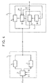
- the device illustrated in FIG. 4 is used to transmit frames of data between equipment transmitter 1 and receiver equipment 2.
- the transmitter equipment 1 comprises means 3 for transmit frames according to said first mode, means 4 to transmit frames according to said second mode, and so-called transmission mode selection means 5 for select, as the case may be, one or other of these means 3 or 4, in this case to apply useful data incident "d", as the case may be to any of these means.
- the receiver equipment 2 comprises, besides means classic and not mentioned here because not referring directly to the invention, to restore useful data transmitted, means 6 for synchronization detection of first mode frame, means 7 for detecting loss of second mode frame synchronization, and means 8 said receiving mode selection to select, as the case may be, one or other of these means.
- the frame synchronization detection means 6 first-class methods operate, according to known techniques, observing the data received through a sliding window and looking for each position in that window slippery, whether or not the synchronization pattern F1 is found.
- the means 7 for detecting synchronization loss second mode frame comprise said means simplified frame synchronization detection, 9, activated by a clock-frame 10 itself set on a position based on a previously acquired knowledge of said frame synchronization, this knowledge prior notice being in this case provided by the means 6 of first mode frame synchronization detection.
- These simplified means of frame synchronization detection 9 are said to be simplified in the sense that, contrary to the means of frame synchronization detection 6, they do not observe data received through a slippery window but at through a single window, whose position is determined by said knowledge previously acquired frame synchronization.
- these simplified means 9 of synchronization detection comprise means for determine how much of the data sequence selected by means of said single window corresponds to synchronization pattern F2.
- these simplified means 9 for detecting synchronization include means to determine in how much the data obtained by applying the same block code only on transmission, with useful data forming a received frame thus delimited by the position of said observation window, correspond to the coding data Error corrector developed on the show.
- Means 5 for selecting transmission mode illustrated in FIG. 4 receive a signal S1 adapted to indicate an initialization of the transmission procedure, and a signal S2 capable of indicating a loss of synchronization frame of the receiver equipment. These means of selection 5 select the means 3 to transmit frames following said first mode when the signal S1 indicates actually an initialization, or when the signal S2 actually indicates a loss of synchronization of frame of the receiver equipment, or the means 4 for transmit frames according to said second mode outside of these two cases.
- Means 8 for selecting mode in reception receive the signal S1 able to indicate an initialization of the transmission procedure, and the signal S2 adapted to indicate a loss of synchronization detection, this last being in this case coming directly from the means 7 frame synchronization loss detection second mode.
- These selection means 8 select the first frame synchronization detection means 6 mode when the signal S1 actually indicates a initialization, or when signal S2 indicates actually a loss of synchronization, or the means 7 synchronization loss detection outside of these two cases.
- the first mode of transmission is to enable the receiving equipment to securely acquire the frame synchronization, and apart from these two cases the second mode of transmission is implemented, thus increasing the load useful transported, and as soon as a loss of synchronization is detected in this second mode, a return to the first mode is realized.
- FIG. 5 illustrates the mode forwarding synchronization loss information carried by the signal S2, from the receiver equipment to the transmitting equipment, in the case of a transmission bidirectional, schematized as two links unidirectional 11 and 12.
- Link 11 connects, as the link of the FIG. 4, a transmitter equipment 1, here said first transmitter equipment, transmission equipment 13, to a receiver equipment 2, here said first equipment receiver, of a transmission equipment.
- link 12 connects a transmitter equipment 15, said second transmitter equipment, transmission equipment 14, to a receiver equipment 16, said second equipment receiver, transmission equipment 13.
- the second transmitter equipment 15 likewise comprises means 17 to transmit frames according to said first mode, means 18 for transmitting frames following said second mode, and means 19 for selecting transmission mode for select, as the case may be, one or other of these means, in this case to apply incidental useful data "d", as the case may be, to one or other of these means.
- the second receiver equipment 16 comprises, in addition to means not specifically illustrated, to restore the transmitted data, means 20 for detecting transmission mode change of the frames transmitted by the transmitter equipment 15, from the second mode to the first fashion.
- the signal S2 applied to the transmitter equipment 1 is derived from the means 20 for detecting a change of mode of transmission of the frames transmitted by the transmitter equipment 15, the means 17 for transmitting frames following said first mode being indeed selected in this equipment transmitter 15 when the signal S2 from the equipment receiver 2 actually indicates a loss detection of synchronization.
- a sequence of useful data to be transmitted that can always decompose in sequences, say here allowed sequences, not containing not themselves of sequence imitating the motif of synchronization, and in sequences, say here sequences forbidden, imitating the motive of synchronization, we have illustrated in FIG. 6 such a data sequence useful ones breaking down as an example into three sequences allowed D1, D2, D3, and in two sequences prohibited X1, X2, said sequence of useful data in this case, in sequence, the sequences D1 X1 D2 X2 D3.
- the modified frame according to the invention allowing, as illustrated in FIGS. 7 to 9, to transmit a such a sequence of useful data, therefore does not include any forbidden sequence such as X1 or X2, but contrary to so-called substitution data, intended to allow, in reception, to reinsert these sequences prohibited among the useful data received.
- said address data, A1 and A2 are contained in so-called substitution, denoted S1 and S2, which substitute respectively to the forbidden sequences X1 and X2 (called also substituted sequences).
- the substitution sequence S1 thus contains an address A1 allowing, in the example illustrated, to a receiving equipment of such frames modified to insert the prohibited sequence X1 between received sequences corresponding to the allowed sequences (or unsubstituted sequences) D1 and D2, and the sequence of substitution S2 thus contains an address A2 allowing such a receiver equipment to insert the prohibited sequence X2 between the received sequences corresponding to the sequences authorized (or unsubstituted) D2 and D3.
- said operating data could also include the number, possibly zero, of substituted sequences contained in the transmitted user data sequence.
- Figure 10 is a diagram for illustrating a example of substitution sequence content.
- This example is thus particularly suitable for case where the delay after which the useful bits are extracted of such a frame in reception may not be fixed, this delay being indeed in this example essentially variable and function of the number of substitution sequences present in the frame, which may be unacceptable in some applications such as for example the application mentioned above to the transmission within the infrastructures of a radio network with mobiles such as especially the GSM network.
- the first substitution sequence S1 is transmitted to a location determined after the first operating data S0, themselves transmitted to a specific location after the synchronization pattern F2 (for example the first substitution sequence S1 is transmitted immediately after the first exploitation data S0, themselves transmitted immediately after the synchronization pattern F2), and the second substitution sequence S2 is transmitted in place of the first substituted sequence X1 (or more generally the n th substitution sequence would be transmitted instead of the n-1 th sequence substituted).
- the second (i.e. here the last) S2 substitution sequence is transmitted to a specific location before the first operating data S0, themselves transferred to a location determined before the synchronization pattern of the next frame (for example the last sequence of substitution is transmitted immediately before the first operating data S0, which are themselves transmitted immediately before the synchronization pattern F2 of the following frame), and the first substitution sequence S1 is transmitted instead of the second one (ie here the last) X2 substituted sequence (or more generally n-1 th substitution sequence would be transmitted instead of the nth substituted sequence).
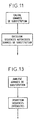
- Fig. 11 is a diagram for illustrating a process for producing such so-called modified frames, valid both for the example of Figure 7 and for the example of Figure 8.
- Figure 12 is an algorithm for illustrating a method for producing such modified frames, following the example shown in Figure 9, from a train incident of useful data.
- a method of generating frames according to one or the other of Figures 11 or 12 is thus implemented, on the diagram of FIG. 5, in the means 18 for transmitting frames according to said second mode.
- the present invention also relates to a transmission device of such modified frames, this device comprising means for implementing the different stages of the emission processes thus described.
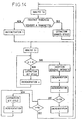
- Fig. 13 is a diagram for illustrating a method for extracting useful data from frames received according to the example of Figure 7.
- Fig. 14 is a diagram for illustrating a method of extracting a useful data stream, from received frames, valid as well for the illustrated example in Figure 8 that, with the adjustments that will be indicated for the example shown in Figure 9.
- a method of extracting useful data following one or the other of FIGS. 13 or 14 is thus in the diagram of Figure 5, to achieve a extracting useful data in the second equipment receiver 16.
- the present invention also relates to a receiving device of such modified frames, this device comprising means for implementing the different steps of the reception methods thus described.
Landscapes
- Engineering & Computer Science (AREA)
- Computer Networks & Wireless Communication (AREA)
- Signal Processing (AREA)
- Synchronisation In Digital Transmission Systems (AREA)
Description
La présente invention concerne les techniques de transmission de données, plus particulièrement les techniques de transmission de données selon lequelles les données transmises sont structurées en blocs appelés aussi trames, comportant des données utiles ainsi que des données dites ici auxiliaires destinées à permettre une synchronisation de trame d'un équipement récepteur sur un équipement émetteur.The present invention relates to the techniques of data transmission, more particularly the data transmission techniques according to which the transmitted data are structured into blocks also called frames, with useful data and data here called auxiliaries intended to allow a frame synchronization of a receiver equipment on a transmitter equipment.
De telles données auxiliaires comportent généralement un motif de synchronisation, appelé encore drapeau, ou fanion, formé d'une séquence prédéterminée de bits disposée habituellement en tête de trame.Such auxiliary data usually include a synchronization pattern, still called a flag, or flag, formed of a predetermined sequence of bits arranged usually at the head of the frame.
Comme il est par ailleurs nécessaire de se prémunir contre les risques d'imitation du motif de synchronisation par les données utiles, de telles données auxiliaires comportent en outre habituellement, insérées parmi les données utiles, des bits de synchronisation destinés à éviter une telle imitation: par exemple, si le motif de synchronisation est une séquence de huit bits à 0, on insère des bits à 1 tous les sept bits.Since it is also necessary to guard against against the risks of imitating the synchronization pattern by the useful data, such auxiliary data in addition usually include, inserted among the data, synchronization bits intended for avoid such imitation: for example, if the motive for synchronization is a sequence of eight bits to 0, we insert bits at 1 every seven bits.
On comprend cependant que l'insertion de telles données auxiliaires se fait au détriment de données utiles, ce qui soulève donc un problème d'efficacité de la trame, notamment lorsque, à débit constant, on souhaiterait pouvoir augmenter la charge utile transmise.It is understood, however, that the insertion of such auxiliary data is to the detriment of useful data, which raises a problem of efficiency of the frame, especially when, at constant flow, we would like to be able to increase the payload transmitted.
A cette fin, la présente invention a pour objet un procédé pour la transmission de trames de données, ces trames comportant d'une part des données dites utiles et d'autre part des données dites auxiliaires destinées à permettre une synchronisation de trame d'un équipement récepteur sur un équipement émetteur, ce procédé étant essentiellement caractérisé en ce que:
- il comporte deux modes de transmission possibles:
- un premier mode, utilisé à l'initialisation ou en cas de perte de synchronisation de trame d'un équipement récepteur appelé premier équipement récepteur, selon lequel un équipement émetteur appelé premier équipement émetteur émet à destination de ce premier équipement récepteur des trames comportant des données auxiliaires suffisantes pour permettre à ce premier équipement récepteur d'acquérir, de façon sûre, ladite synchronisation de trame, ces données auxiliaires incluant notamment un motif de synchronisation,
- un deuxième mode, utilisé en dehors de ces deux cas, selon lequel ledit premier équipement émetteur émet des trames comportant des données auxiliaires insuffisantes pour permettre audit premier équipement récepteur d'acquérir, de façon sûre, ladite synchronisation de trame, mais permettant, grâce en outre à une connaissance de ladite synchronisation de trame acquise préalablement, dans ledit premier mode, de déterminer une perte de synchronisation de trame,
- une perte de synchronisation de trame par ledit premier équipement récepteur est signalée audit premier équipement émetteur par passage d'un deuxième équipement émetteur, associé, dans un même équipement de transmission, audit premier équipement récepteur, dudit deuxième mode de transmission vers ledit premier mode de transmission, et détection de ce changement de mode de transmission par un deuxième équipement récepteur, associé, dans un même équipement de transmission, audit premier équipement émetteur, et,
- ledit deuxième équipement émetteur transmet, dans ledit deuxième mode , des trames dites modifiées ne comportant aucune séquence de données utiles imitant le motif de synchronisation du premier mode, dites aussi séquences interdites, celles-ci étant remplacées par des données dites de substitution destinées à permettre, en réception,de pouvoir réinsérer ces séquences interdites parmi les données utiles reçues.
- it has two possible modes of transmission:
- a first mode, used at the initialization or in the event of loss of frame synchronization of a receiving equipment called first receiving equipment, according to which a sending equipment called first transmitting equipment transmits frames containing data to this first receiving equipment; auxiliaries sufficient to allow this first receiving equipment to securely acquire said frame synchronization, these auxiliary data including in particular a synchronization pattern,
- a second mode, used outside of these two cases, according to which said first transmitting equipment transmits frames having insufficient auxiliary data to enable said first receiving equipment to securely acquire said frame synchronization, but allowing, thanks in part to in addition to a knowledge of said previously acquired frame synchronization, in said first mode, to determine a frame synchronization loss,
- a loss of frame synchronization by said first receiving equipment is signaled to said first transmitting equipment by passing a second associated transmitting equipment, in the same transmission equipment, to said first receiving equipment, said second transmission mode to said first transmission mode; transmission, and detection of this change of transmission mode by a second receiver equipment, associated, in the same transmission equipment, to said first transmitting equipment, and,
- said second transmitting equipment transmits, in said second mode, so-called modified frames having no sequence of useful data mimicking the synchronization pattern of the first mode, also called forbidden sequences, these being replaced by so-called substitution data intended to allow , in reception, to be able to reinsert these prohibited sequences among the received useful data.
Ainsi, en cas d'initialisation ou de perte de synchronisation, le premier mode de transmission est mis en oeuvre afin de permettre à l'équipement récepteur d'acquérir, de façon sûre, la synchronisation de trame, et en dehors de ces deux cas le deuxième mode de transmission est mis en oeuvre, permettant ainsi d'accroítre la charge utile transportée, et dès qu'une perte de synchronisation est détectée dans ce deuxième mode, un retour au premier mode est réalisé. Un système utilisant deux modes de transmission est décrit dans US-A-5 420 865.Thus, in case of initialization or loss of synchronization, the first mode of transmission is to enable the receiving equipment to securely acquire the frame synchronization, and apart from these two cases the second mode of transmission is implemented, thus increasing the load useful transported, and as soon as a loss of synchronization is detected in this second mode, a return to the first mode is realized. A system using two modes of transmission is described in US-A-5,420,865.
En outre, tout problème dû à un risque de fausse détection d'un tel passage du deuxième mode au premier mode, dû lui-même à un risque d'imitation du motif de synchronisation du premier mode par les données utiles transmises dans le deuxième mode, est évité grâce à la transmission, dans le deuxième mode, selon lesdites trames modifiées.In addition, any problem due to a risk of false detecting such a transition from the second mode to the first mode, due to a risk of imitation of the motive of synchronization of the first mode by the useful data transmitted in the second mode, is avoided thanks to the transmission, in the second mode, according to said frames changed.
La présente invention a également pour objet un dispositif de transmission correspondant.The present invention also relates to a corresponding transmission device.
La présente invention a également pour objet une telle trame modifiée.The present invention also relates to such a modified frame.
La présente invention est notamment applicable à des trames telles que les trames dites V110 permettant de transporter des données à des débits non sous-multiples de 64 kbit/s, telles que notamment celles obtenues pour les services de transmission de données offerts par le réseau GSM ("Global System for Mobile communications"), dans des canaux à 64 kbit/s.The present invention is particularly applicable to frames such as so-called V110 frames allowing carry data at non-submultiple rates of 64 kbit / s, such as those obtained for data transmission services offered by the network GSM ("Global System for Mobile Communications"), in 64 kbit / s channels.
D'autres objets et caractéristiques de la présente invention apparaítront à la lecture de la description suivante d'exemples de réalisation, faite en relation avec les dessins ci-annexés dans lesquels:
- la figure 1 est un diagramme destiné à illustrer un exemple de trame transmise suivant ledit premier mode,
- la figure 2 est un diagramme destiné à illustrer un premier exemple de trame transmise suivant ledit deuxième mode,
- la figure 3 est un diagramme destiné à illustrer un deuxième exemple de trame transmise suivant ledit deuxième mode,
- la figure 4 est un schéma synoptique destiné à faire comprendre, pour simplifier dans le cas d'une liaison unidirectionnelle, le principe d'une transmission utilisant lesdits premier et deuxième modes de transmission,
- la figure 5 est un schéma synoptique destiné à illustrer un dispositif de transmission utilisant, dans le cas d'une liaison bidirectionnelle, lesdits premier et deuxième modes de transmission,
- la figure 6 est un diagramme destiné à illustrer un exemple de séquence de données utiles à transmettre, afin d'expliquer le principe de formation desdites trames modifiées,
- les figures 7, 8, et 9 sont des diagrammes destinés à illustrer respectivement un premier, un deuxième et un troisième exemple de trame modifiée, permettant la transmission d'une telle séquence de données utiles,
- la figure 10 est un diagramme destiné à illustrer un exemple de contenu de séquences dites de substitution transmises dans une telle trame modifiée,
- la figure 11 est un diagramme destiné à illustrer un procédé d'élaboration de trames modifiées suivant ledit premier exemple ou suivant ledit deuxième exemple, à partir d'un train incident de données utiles,
- la figure 12 est un diagramme destiné à illustrer un procédé d'élaboration de trames modifiées suivant ledit troisième exemple, à partir d'un train incident de données utiles,
- la figure 13 est un diagramme destiné à illustrer un procédé d'extraction de données utiles, à partir de trames modifiées reçues suivant ledit premier exemple,
- la figure 14 est un diagramme destiné à illustrer un procédé d'extraction d'un train de données utiles, à partir de trames modifiées reçues suivant ledit deuxième exemple ou suivant ledit troisième exemple.
- FIG. 1 is a diagram intended to illustrate an example of frame transmitted according to said first mode,
- FIG. 2 is a diagram intended to illustrate a first example of a frame transmitted according to said second mode,
- FIG. 3 is a diagram intended to illustrate a second example of frame transmitted according to said second mode,
- FIG. 4 is a block diagram intended to explain, for simplicity in the case of a unidirectional link, the principle of a transmission using said first and second modes of transmission,
- FIG. 5 is a block diagram for illustrating a transmission device using, in the case of a bidirectional link, said first and second modes of transmission,
- FIG. 6 is a diagram intended to illustrate an example of a sequence of useful data to be transmitted, in order to explain the principle of formation of said modified frames,
- FIGS. 7, 8 and 9 are diagrams for respectively illustrating a first, a second and a third exemplary modified frame, allowing the transmission of such a sequence of useful data,
- FIG. 10 is a diagram intended to illustrate an exemplary content of so-called substitution sequences transmitted in such a modified frame,
- FIG. 11 is a diagram intended to illustrate a method of generating modified frames according to said first example or according to said second example, from a data payload train,
- FIG. 12 is a diagram intended to illustrate a method for generating modified frames according to said third example, from a data payload train,
- FIG. 13 is a diagram intended to illustrate a method of extracting useful data, from modified frames received according to said first example,
- FIG. 14 is a diagram for illustrating a method of extracting a useful data stream from modified frames received according to said second example or according to said third example.
Dans l'exemple de trame transmise suivant ledit premier mode, illustré sur la figure 1, lesdites données auxiliaires comportent un motif de synchronisation appelé premier motif de synchronisation, noté F1, formé d'une séquence prédéterminée de bits placée en l'occurrence en tête de la trame, ainsi que des bits de synchronisation notés f1, f2, ...fn, insérés parmi les données utiles, notées D1, D2, ...Dn, et destinés à éviter une imitation de ce motif de synchronisation par ces données utiles.In the frame example transmitted according to said first mode, illustrated in Figure 1, said data Auxiliaries have a synchronization pattern called first synchronization pattern, denoted F1, formed of a predetermined sequence of bits placed here in head of the frame, as well as synchronization bits denoted f1, f2, ... fn, inserted among the useful data, denoted D1, D2, ... Dn, and intended to avoid an imitation of this synchronization pattern by this useful data.
Dans l'exemple de trame transmise suivant ledit deuxième mode, illustré sur la figure 2, lesdites données auxiliaires ne comportent qu'un motif de synchronisation appelé deuxième motif de synchronisation, noté F2, de longueur différente (notamment inférieure) à celle du premier motif de synchronisation F1.In the frame example transmitted according to said second mode, illustrated in FIG. 2, said data auxiliaries only have a synchronization pattern called second synchronization pattern, denoted F2, of different length (especially lower) than the first synchronization pattern F1.
Dans l'exemple de trame transmise suivant ledit deuxième mode, illustré sur la figure 3, lesdites données auxiliaires ne comportent que des données, notées C, de codage correcteur d'erreurs obtenues en appliquant un code correcteur d'erreurs du type code en bloc aux données utiles destinées à être transmises à l'intérieur d'un même bloc, ou trame.In the frame example transmitted according to said second mode, illustrated in FIG. 3, said data auxiliaries only contain data, denoted C, from error correction coding obtained by applying a code block code error corrector to the payload intended to be transmitted within the same block, or frame.
On notera que dans ce dernier exemple lesdites données auxiliaires permettent ainsi d'obtenir en outre une protection contre les erreurs de transmission des données utiles ainsi transmises.It will be noted that in the latter example said data auxiliaries thus make it possible to obtain, in addition, protection against data transmission errors useful and transmitted.
D'autres exemples de trames que ceux illustrés sur les figures 1 à 3 sont bien entendu possibles; en outre, des trames transmises suivant ledit deuxième mode peuvent être obtenues en utilisant, comme données auxiliaires, à la fois un motif de synchronisation et des données de codage correcteur d'erreurs, éventuellement de longueur inférieure à ceux utilisés respectivement dans les exemples de réalisation illustrés sur les figures 2 et 3. Other examples of frames than those illustrated on the Figures 1 to 3 are of course possible; in addition, frames transmitted according to said second mode may be obtained by using, as auxiliary data, both a synchronization pattern and encoding data error corrector, possibly of shorter length to those used respectively in the examples of embodiment illustrated in Figures 2 and 3.
On comprend, dans ces différents exemples, que les données auxiliaires des trames transmises suivant ledit premier mode permettent à l'équipement récepteur d'acquérir de façon sûre la synchronisation de trame, alors que les données auxiliaires des trames transmises suivant ledit deuxième mode sont insuffisantes pour permettre à l'équipement récepteur d'acquérir de façon sûre une telle synchronisation. Cependant, grâce en outre à une connaissance de ladite synchronisation de trame acquise préalablement, dans ledit premier mode, elles permettent de détecter une perte de synchronisation de trame.In these different examples, it is understood that the ancillary data of transmitted frames according to said first mode allow the receiving equipment to acquire the frame synchronization, while the ancillary data of transmitted frames according to said second mode are insufficient to allow the receiving equipment to safely acquire such synchronization. However, thanks also to a knowledge of said acquired frame synchronization previously, in said first mode, they allow detect a loss of frame synchronization.
En outre, pour accélérer le retour à la synchronisation de trame de l'équipement récepteur en cas de perte de cette synchronisation, les trames transmises suivant ledit premier mode pourront comporter, au lieu de données utiles, des bits de valeur égale à celle des bits de synchronisation.In addition, to speed up the return to frame synchronization of the receiver equipment in case of loss of this synchronization, the transmitted frames following said first mode may include, instead of data, bits of value equal to that of the bits of synchronization.
Le dispositif illustré sur la figure 4 est utilisé
pour transmettre des trames de données entre un équipement
émetteur 1 et un équipement récepteur 2.The device illustrated in FIG. 4 is used
to transmit frames of data between
L'équipement émetteur 1 comporte des moyens 3 pour
émettre des trames suivant ledit premier mode, des moyens 4
pour émettre des trames suivant ledit deuxième mode, et des
moyens 5 dits de sélection de mode en émission pour
sélectionner, suivant le cas, l'un ou l'autre de ces moyens
3 ou 4, en l'occurrence pour appliquer des données utiles
incidentes "d", suivant le cas à l'un ou l'autre de ces
moyens.The
L'équipement récepteur 2 comporte, outre des moyens
classiques et non mentionnés ici car ne se rapportant pas
directement à l'invention, pour restituer les données utiles
transmises, des moyens 6 de détection de synchronisation de
trame de premier mode, des moyens 7 de détection de perte de
synchronisation de trame de deuxième mode, et des moyens 8
dits de sélection de mode en réception pour sélectionner,
suivant le cas, l'un ou l'autre de ces moyens. The
Les moyens 6 de détection de synchronisation de trame de premier mode opèrent, suivant des techniques connues, en observant les données reçues à travers une fenêtre glissante et en recherchant, pour chaque position de cette fenêtre glissante, si le motif de synchronisation F1 est ou non retrouvé.The frame synchronization detection means 6 first-class methods operate, according to known techniques, observing the data received through a sliding window and looking for each position in that window slippery, whether or not the synchronization pattern F1 is found.
Les moyens 7 de détection de perte de synchronisation
de trame de deuxième mode comportent des moyens dits
simplifiés de détection de synchronisation de trame, 9,
activés par une horloge-trame 10 elle-même calée sur une
position fonction d'une connaissance préalablement acquise
de ladite synchronisation de trame, cette connaissance
préalable étant en l'occurrence fournie par les moyens 6 de
détection de synchronisation de trame de premier mode. Ces
moyens simplifiés de détection de synchronisation de trame 9
sont dits simplifiés au sens où, contrairement aux moyens de
détection de synchronisation de trame 6, ils n'observent pas
les données reçues à travers une fenêtre glissante mais à
travers une fenêtre unique, dont la position est donc
déterminée grâce à ladite connaissance préalablement acquise
de la synchronisation de trame.The means 7 for detecting synchronization loss
second mode frame comprise said means
simplified frame synchronization detection, 9,
activated by a clock-
A titre d'exemple, dans le cas du deuxième mode de transmission illustré sur la figure 2, ces moyens simplifiés 9 de détection de synchronisation comportent des moyens pour déterminer dans quelle mesure la séquence de données sélectionnée au moyen de ladite fenêtre unique correspond au motif de synchronisation F2.For example, in the case of the second mode of transmission illustrated in Figure 2, these simplified means 9 of synchronization detection comprise means for determine how much of the data sequence selected by means of said single window corresponds to synchronization pattern F2.
Dans le cas du deuxième mode de transmission illustré
sur la figure 3, ces moyens simplifiés 9 de détection de
synchronisation comportent des moyens pour déterminer dans
quelle mesure les données obtenues en appliquant le même
code en bloc qu'à l'émission, aux données utiles formant une
trame reçue ainsi délimitée grâce à la position de ladite
fenêtre d'observation, correspondent aux données de codage
correcteur d'erreurs élaborées à l'émission. In the case of the second mode of transmission illustrated
in FIG. 3, these simplified
Les moyens 5 de sélection de mode en émission illustrés sur la figure 4 reçoivent un signal S1 apte à indiquer une initialisation de la procédure de transmission, et un signal S2 apte à indiquer une perte de synchronisation de trame de l'équipement récepteur. Ces moyens de sélection 5 sélectionnent les moyens 3 pour émettre des trames suivant ledit premier mode lorsque le signal S1 indique effectivement une initialisation, ou lorsque le signal S2 indique effectivement une perte de synchronisation de trame de l'équipement récepteur, ou les moyens 4 pour émettre des trames suivant ledit deuxième mode en dehors de ces deux cas.Means 5 for selecting transmission mode illustrated in FIG. 4 receive a signal S1 adapted to indicate an initialization of the transmission procedure, and a signal S2 capable of indicating a loss of synchronization frame of the receiver equipment. These means of selection 5 select the means 3 to transmit frames following said first mode when the signal S1 indicates actually an initialization, or when the signal S2 actually indicates a loss of synchronization of frame of the receiver equipment, or the means 4 for transmit frames according to said second mode outside of these two cases.
Les moyens 8 de sélection de mode en réception
reçoivent le signal S1 apte à indiquer une initialisation de
la procédure de transmission, et le signal S2 apte à
indiquer une détection de perte de synchronisation, ce
dernier étant en l'occurrence issu directement des moyens 7
de détection de perte de synchronisation de trame de
deuxième mode. Ces moyens de sélection 8 sélectionnent les
moyens 6 de détection de synchronisation de trame de premier
mode lorsque le signal S1 indique effectivement une
initialisation, ou lorsque le signal S2 indique
effectivement une perte de synchronisation, ou les moyens 7
de détection de perte de synchronisation en dehors de ces
deux cas.
Ainsi, en cas d'initialisation ou de perte de synchronisation, le premier mode de transmission est mis en oeuvre afin de permettre à l'équipement récepteur d'acquérir, de façon sûre, la synchronisation de trame, et en dehors de ces deux cas le deuxième mode de transmission est mis en oeuvre, permettant ainsi d'accroítre la charge utile transportée, et dès qu'une perte de synchronisation est détectée dans ce deuxième mode, un retour au premier mode est réalisé.Thus, in case of initialization or loss of synchronization, the first mode of transmission is to enable the receiving equipment to securely acquire the frame synchronization, and apart from these two cases the second mode of transmission is implemented, thus increasing the load useful transported, and as soon as a loss of synchronization is detected in this second mode, a return to the first mode is realized.
Le schéma de la figure 5 permet d'illustrer le mode
d'acheminement de l'information de perte de synchronisation
portée par le signal S2, de l'équipement récepteur jusqu'à
l'équipement émetteur, dans le cas d'une transmission
bidirectionnelle, schématisée sous la forme de deux liaisons
unidirectionnelles 11 et 12. Pour simplifier, les éléments
communs à la figure 4 et à la figure 5 portent les mêmes
références. La liaison 11 relie, comme la liaison de la
figure 4, un équipement émetteur 1, dit ici premier
équipement émetteur, d'un équipement de transmission 13, à
un équipement récepteur 2, dit ici premier équipement
récepteur, d'un équipement de transmission 14. De même la
liaison 12 relie un équipement émetteur 15, dit deuxième
équipement émetteur, de l'équipement de transmission 14, à
un équipement récepteur 16, dit deuxième équipement
récepteur, de l'équipement de transmission 13.The diagram in Figure 5 illustrates the mode
forwarding synchronization loss information
carried by the signal S2, from the receiver equipment to
the transmitting equipment, in the case of a transmission
bidirectional, schematized as two links
unidirectional 11 and 12. For simplicity, the elements
common to Figure 4 and Figure 5 are the same
references. Link 11 connects, as the link of the
FIG. 4, a
Pour assurer l'achemininement de l'information de
perte de synchronisation portée par le signal S2, de
l'équipement récepteur 2 jusqu'à l'équipement émetteur 1, le
deuxième équipement émetteur 15 comporte de même des moyens
17 pour émettre des trames suivant ledit premier mode, des
moyens 18 pour émettre des trames suivant ledit deuxième
mode, et des moyens 19 de sélection de mode en émission pour
sélectionner, suivant le cas, l'un ou l'autre de ces moyens,
en l'occurrence pour appliquer des données utiles incidentes
"d'", suivant le cas à l'un ou l'autre de ces moyens.To ensure the routing of information from
loss of synchronization carried by the signal S2,
the
Le deuxième équipement récepteur 16 comporte, outre
des moyens non illustrés spécifiquement, pour restituer les
données utiles transmises, des moyens 20 de détection de
changement de mode de transmission des trames émises par
l'équipement émetteur 15, du deuxième mode vers le premier
mode.The
Le signal S2 appliqué à l'équipement émetteur 1 est
issu des moyens 20 de détection de changement de mode de
transmission des trames émises par l'équipement émetteur 15,
les moyens 17 d'émission de trames suivant ledit premier
mode étant en effet sélectionnés dans cet équipement
émetteur 15 lorsque le signal S2 issu de l'équipement
récepteur 2 indique effectivement une détection de perte de
synchronisation.The signal S2 applied to the
Ces moyens 20 de détection de changement de mode de transmission comportent, opérant en parallèle:
- des moyens 201 de détection de synchronisation de trame de premier mode opérant, suivant des techniques connues, en observant les données reçues à travers une fenêtre glissante et en recherchant, pour chaque position de cette fenêtre glissante, si le motif de synchronisation du premier mode est ou non retrouvé,
- des moyens 202 de détection de perte de synchronisation de trame de deuxième mode, qui peuvent eux-mêmes comporter, comme les moyens 7, des moyens dits simplifiés de détection de synchronisation de trame, activés par une horloge-trame elle-même calée sur une position fonction d'une connaissance préalablement acquise, dans le premier mode, de ladite synchronisation de trame.
- first-mode frame synchronization detection means 201 operating, according to known techniques, by observing the received data through a sliding window and searching, for each position of this sliding window, whether the synchronization pattern of the first mode is or not found,
- second mode frame synchronization loss detection means 202, which themselves may comprise, as the means 7, so-called simplified means of frame synchronization detection, activated by a frame clock itself set on a position according to a previously acquired knowledge, in the first mode, of said frame synchronization.
Ainsi, lorsque l'une ou l'autre des deux conditions:
perte de synchronisation dans le deuxième mode (détectée par
les moyens 202), ou reprise de synchronisation dans le
premier mode (détectée par les moyens 201), est réalisée, ce
qui est indiqué par des moyens 203, une détection de
changement de mode est réalisée par ces moyens 20.Thus, when one or the other of the two conditions:
loss of synchronization in the second mode (detected by
the means 202), or resumption of synchronization in the
first mode (detected by the means 201), is performed, this
which is indicated by
On notera que même si , pour simplifier, on n'a fait
ressortir, dans la description qui précède, que les éléments
nécessaires à la transmission des données "d" de
l'équipement de transmission 13 vers l'équipement de
transmission 14, le principe de transmission est bien
entendu symétrique et s'applique aussi bien pour la
transmission des données "d"' de l'équipement de
transmission 14 vers l'équipement de transmission 13.Note that even if, for simplicity, we did not
in the above description, that the elements
necessary for the transmission of data "d" of
the
Par ailleurs, tout problème dû à un risque de fausse détection d'un tel passage du deuxième mode au premier mode, dû lui-même à un risque d'imitation du motif de synchronisation du premier mode par les données utiles transmises dans le deuxième mode est évité, comme expliqué maintenant en relation avec les figures suivantes, dans lesquelles les trames considérées sont donc, même si cela n'est pas précisé, des trames selon le deuxième mode.Moreover, any problem due to a risk of false detecting such a transition from the second mode to the first mode, due to a risk of imitation of the motive of synchronization of the first mode by the useful data transmitted in the second mode is avoided, as explained now in relation to the following figures, in which frames are considered, even if that is not specified, frames according to the second mode.
Comme illustré sur la figure 6, une séquence de données utiles à transmettre pouvant toujours se décomposer en séquences, dites ici séquences autorisées, ne contenant pas elles-mêmes de séquence imitant le motif de synchronisation, et en séquences, dites ici séquences interdites, imitant le motif de synchronisation, on a illustré sur la figure 6 une telle séquence de données utiles se décomposant à titre d'exemple en trois séquences autorisées notées D1, D2, D3, et en deux séquences interdites notées X1, X2, ladite séquence de données utiles comportant en l'occurrence, dans l'ordre, les séquences D1 X1 D2 X2 D3.As illustrated in Figure 6, a sequence of useful data to be transmitted that can always decompose in sequences, say here allowed sequences, not containing not themselves of sequence imitating the motif of synchronization, and in sequences, say here sequences forbidden, imitating the motive of synchronization, we have illustrated in FIG. 6 such a data sequence useful ones breaking down as an example into three sequences allowed D1, D2, D3, and in two sequences prohibited X1, X2, said sequence of useful data in this case, in sequence, the sequences D1 X1 D2 X2 D3.
La trame modifiée suivant l'invention, permettant, comme illustré sur les figures 7 à 9, de transmettre une telle séquence de données utiles, ne comporte donc aucune séquence interdite telle que X1 ou X2, mais comporte au contraire des données dites de substitution, destinées à permettre, en réception, de pouvoir réinsérer ces séquences interdites parmi les données utiles reçues.The modified frame according to the invention, allowing, as illustrated in FIGS. 7 to 9, to transmit a such a sequence of useful data, therefore does not include any forbidden sequence such as X1 or X2, but contrary to so-called substitution data, intended to allow, in reception, to reinsert these sequences prohibited among the useful data received.
Ces données de substitution comportent elles-mêmes avantageusement deux types de données:
- des données dites ici d'exploitation, permettant à un équipement récepteur de telles trames modifiées de déterminer dans quelle mesure la séquence de données utiles transmise diffère de la séquence de données utiles à transmettre, c'est-à-dire dans quelle mesure des séquences interdites sont présentes dans la séquence de données utiles à transmettre,
- des données dites ici d'adresse, permettant à un équipement récepteur de telles trames modifiées de déterminer plus précisément le ou les emplacements où une séquence interdite doit être insérée parmi les données utiles reçues.
- so-called operating data, allowing a receiving equipment of such modified frames to determine to what extent the transmitted user data sequence differs from the useful data sequence to be transmitted, i.e. to what extent sequences prohibited are present in the sequence of useful data to be transmitted,
- so-called address data, allowing a receiving equipment such modified frames to more precisely determine the location or locations where a prohibited sequence is to be inserted among the received payload data.
Dans l'exemple illustré, lesdites données d'adresse, notées A1 et A2, sont contenues dans des séquences dites de substitution, notées S1 et S2, qui se substituent respectivement aux séquences interdites X1 et X2 ( dites aussi séquences substituées). La séquence de substitution S1 contient ainsi une adresse A1 permettant, dans l'exemple illustré, à un équipement récepteur de telles trames modifiées d'insérer la séquence interdite X1 entre les séquences reçues correspondant aux séquences autorisées (ou séquences non substituées) D1 et D2, et la séquence de substitution S2 contient ainsi une adresse A2 permettant à un tel équipement récepteur d'insérer la séquence interdite X2 entre les séquences reçues correspondant aux séquences autorisées ( ou non substituées) D2 et D3.In the illustrated example, said address data, A1 and A2, are contained in so-called substitution, denoted S1 and S2, which substitute respectively to the forbidden sequences X1 and X2 (called also substituted sequences). The substitution sequence S1 thus contains an address A1 allowing, in the example illustrated, to a receiving equipment of such frames modified to insert the prohibited sequence X1 between received sequences corresponding to the allowed sequences (or unsubstituted sequences) D1 and D2, and the sequence of substitution S2 thus contains an address A2 allowing such a receiver equipment to insert the prohibited sequence X2 between the received sequences corresponding to the sequences authorized (or unsubstituted) D2 and D3.
A titre d'exemple lesdites données d'exploitation peuvent comporter:
- des premières données d'exploitation, telles que celles notées S0 sur les figures 7 à 9, transmises à un emplacement déterminé après le motif de synchronisation considéré, soit F2, (par exemple immédiatement après ce motif de synchronisation) , et indiquant si la séquence de données utiles transmise diffère ou non de la séquence de données utiles à transmettre, c'est-à-dire si la séquence de données utiles transmise contient ou non des séquences substituées,
- des deuxièmes données d'exploitation, telles que celles notées S10 et S20 sur les figures 7 à 9, transmises avantageusement dans lesdites séquences de substitution telles que S1 et S2, et indiquant si chacune de ces séquences de substitution est ou non la dernière de la trame transmise.
- first operating data, such as those noted S0 in FIGS. 7 to 9, transmitted at a given location after the synchronization pattern in question, namely F2 (for example immediately after this synchronization pattern), and indicating whether the sequence transferred useful data differs from the useful data sequence to be transmitted, that is, whether or not the transmitted user data sequence contains substituted sequences,
- second operating data, such as those denoted S10 and S20 in FIGS. 7 to 9, advantageously transmitted in said substitution sequences such as S1 and S2, and indicating whether each of these substitution sequences is or is not the last of the transmitted frame.
Suivant un autre exemple, non illustré spécifiquement, lesdites données d'exploitation pourraient aussi comporter le nombre, éventuellement nul, de séquences substituées contenues dans la séquence de données utiles transmise. In another example, not specifically illustrated, said operating data could also include the number, possibly zero, of substituted sequences contained in the transmitted user data sequence.
La figure 10 est un diagramme destiné à illustrer un exemple de contenu de séquence de substitution.Figure 10 is a diagram for illustrating a example of substitution sequence content.
Dans cet exemple une séquence de substitution, notée de manière générale S, comporte:
- lesdites deuxièmes données d'exploitation telles que S10 par exemple, constituées par exemple par un bit à 1 ou à 0 suivant que la séquence de substitution considérée est ou non la dernière de la trame transmise,
- des données d'adresse, telles que A1 ou A2, constituées par exemple par un nombre binaire à "n" bits indiquant le rang d'un bit dans une séquence de 2n bits utiles à transmettre,
- des données, notées P, de protection de cette séquence de substitution contre les erreurs de transmission (ces données de protection étant par exemple constituées par un bit de parité),
- des données dites de verrouillage, notées V, destinées à éviter qu'une séquence interdite soit reproduite par introduction d'une séquence de substitution dans la trame transmise (ces données de verrouillage étant par exemple constituées par un bit à 1 dans l'exemple considéré de séquence interdite formée uniquement de bits à 0).
- said second operating data, such as S10, for example, constituted for example by a 1 or 0 bit depending on whether the substitution sequence considered is the last of the transmitted frame or not,
- address data, such as A1 or A2, constituted for example by a binary number with "n" bits indicating the rank of a bit in a sequence of 2 n bits useful for transmission,
- data, denoted P, of protection of this substitution sequence against transmission errors (this protection data being for example constituted by a parity bit),
- so-called locking data, denoted V, intended to prevent a prohibited sequence from being reproduced by introducing a substitution sequence into the transmitted frame (this locking data being for example constituted by a 1-bit in the example under consideration). forbidden sequence formed only of bits at 0).
Dans l'exemple illustré sur la figure 7, l'ensemble formé par les données d'exploitation et les données d'adresse ( c'est-à-dire l'ensemble formé par les premières données d'exploitation S0 et les séquences de substitution telles que S1, S2 incluant elles-mêmes des deuxièmes données d'exploitation telles que S10 et S20 et des données d'adresse telles que A1 et A2) est transmis avant l'ensemble des données utiles.In the example illustrated in FIG. formed by operating data and data of address (that is to say the whole formed by the first S0 operating data and substitution sequences such as S1, S2 including themselves second data such as S10 and S20 and data such as A1 and A2) is transmitted before the set useful data.
Cet exemple convient ainsi plus particulièrement au cas où le délai au bout duquel les bits utiles sont extraits d'une telle trame en réception peut ne pas être fixe, ce délai étant en effet dans cet exemple essentiellement variable et fonction du nombre de séquences de substitution présentes dans la trame, ce qui peut être inacceptable dans certaines applications telles que par exemple l'application précitée à la transmission au sein des infrastructures d'un réseau de radiocommunication avec des mobiles tel que notamment le réseau GSM.This example is thus particularly suitable for case where the delay after which the useful bits are extracted of such a frame in reception may not be fixed, this delay being indeed in this example essentially variable and function of the number of substitution sequences present in the frame, which may be unacceptable in some applications such as for example the application mentioned above to the transmission within the infrastructures of a radio network with mobiles such as especially the GSM network.
Ceci est évité dans l'exemple illustré sur la figure 8.This is avoided in the example shown in the figure 8.
Plus précisément, dans cet exemple, la première séquence de substitution S1 est transmise à un emplacement déterminé après les premières données d'exploitation S0, elles-mêmes transmises à un emplacement déterminé après le motif de synchronisation F2 (par exemple la première séquence de substitution S1 est transmise immédiatement après les premières données d'exploitation S0, elles-mêmes transmises immédiatement après le motif de synchronisation F2), et la deuxième séquence de substitution S2 est transmise à la place de la première séquence substituée X1 (ou plus généralement la n ième séquence de substitution serait transmise à la place de la n-1 ième séquence substituée).More specifically, in this example, the first substitution sequence S1 is transmitted to a location determined after the first operating data S0, themselves transmitted to a specific location after the synchronization pattern F2 (for example the first substitution sequence S1 is transmitted immediately after the first exploitation data S0, themselves transmitted immediately after the synchronization pattern F2), and the second substitution sequence S2 is transmitted in place of the first substituted sequence X1 (or more generally the n th substitution sequence would be transmitted instead of the n-1 th sequence substituted).
Les exemples illustrés sur les figures 7 et 8 conviennent en outre plus particulièrement au cas où aucune contrainte n'existe sur le délai au bout duquel de telles trames peuvent ainsi être élaborées à partir d'un train de données utiles incident, ce délai étant en effet dans ces exemples égal au temps d'analyse total d'une séquence de données utiles incidente, nécessaire pour permettre d'obtenir lesdites données d'exploitation, ce qui peut être prohibitif dans certaines applications telles que notamment l'application précitée à la transmission de données au sein des infrastructures d'un réseau de radiocommunication avec des mobiles tel que notamment le réseau GSM.The examples illustrated in Figures 7 and 8 are moreover particularly suitable in the case where no constraint does not exist on the period after which such frames can thus be developed from a train of incidental data, this delay being in fact in these examples equal to the total scan time of a sequence of incidental data, necessary to enable to obtain said operating data, which can be prohibitive in certain applications such as the aforementioned application to the transmission of data within infrastructure of a radiocommunication network with mobiles such as in particular the GSM network.
L'exemple illustré sur la figure 9 permet au contraire de satisfaire à une telle contrainte. Dans cet exemple, lesdites données d'exploitation se présentent de façon inversée par rapport au cas illustré sur les figures 7 et 8, en ce sens que:
- les premières données d'exploitation telles que S0 indiquant si la séquence de données utiles transmise diffère ou non de la séquence de données utiles à transmettre sont insérées non pas après le motif de synchronisation de la trame considérée, mais en fin de trame, c'est-à-dire avant le motif de synchronisation de la trame suivante,
- les deuxièmes données d'exploitation telles que S10 et S20 n'indiquent plus si la séquence de substitution correspondante telle que S1 et S2 est ou non la dernière à partir du début de la trame, mais si elle est ou non la dernière à partir de la fin de la trame.
- the first operating data such as S0 indicating whether the transmitted user data sequence differs from the useful data sequence to be transmitted is inserted not after the synchronization pattern of the frame in question, but at the end of the frame, that is, before the synchronization pattern of the next frame,
- the second operating data such as S10 and S20 no longer indicate whether the corresponding substitution sequence such as S1 and S2 is the last from the start of the frame, but whether or not it is the last one from the end of the frame.
Il est à noter qu'une telle trame ne peut alors être exploitée en réception avant de l'avoir reçue en totalité, mais que ceci n'introduit pas de retard notable, contrairement audit temps d'analyse qui aurait été nécessaire en émission.It should be noted that such a frame can not be operated in reception before receiving it in full, but this does not introduce any noticeable delay, unlike the analysis time that would have been necessary in emission.
Un début d'analyse de ladite séquence de données utiles à transmettre reste en outre nécessaire avant de pouvoir élaborer une trame correspondante, d'où un léger retard à l'émission de telles trames, comme cela apparaítra sur la figure 12.A beginning of analysis of said data sequence useful to transmit remains further necessary before can develop a corresponding frame, hence a slight delay in the transmission of such frames, as will appear in Figure 12.
En outre, dans l'exemple illustré, la deuxième (c'est-à-dire ici la dernière) séquence de substitution S2 est transmise à un emplacement déterminé avant les premières données d'exploitation S0, elles-mêmes tranmises à un emplacement déterminé avant le motif de synchronisation de la trame suivante (par exemple la dernière séquence de substitution est transmise immédiatement avant les premières données d'exploitation S0, elles-mêmes transmises immédiatement avant le motif de synchronisation F2 de la trame suivante), et la première séquence de substitution S1 est transmise à la place de la deuxième (c'est-à-dire ici la dernière) séquence substituée X2 (ou plus généralement la n-1 ième séquence de substitution serait transmise à la place de la n ième séquence substituée). In addition, in the illustrated example, the second (i.e. here the last) S2 substitution sequence is transmitted to a specific location before the first operating data S0, themselves transferred to a location determined before the synchronization pattern of the next frame (for example the last sequence of substitution is transmitted immediately before the first operating data S0, which are themselves transmitted immediately before the synchronization pattern F2 of the following frame), and the first substitution sequence S1 is transmitted instead of the second one (ie here the last) X2 substituted sequence (or more generally n-1 th substitution sequence would be transmitted instead of the nth substituted sequence).
La figure 11 est un diagramme destiné à illustrer un procédé d'élaboration de telles trames dites modifiées, valable aussi bien pour l'exemple de la figure 7 que pour l'exemple de la figure 8.Fig. 11 is a diagram for illustrating a process for producing such so-called modified frames, valid both for the example of Figure 7 and for the example of Figure 8.
Ce procédé comporte les étapes de:
- calcul de données de substitution, à partir de données utiles incidentes,
- émission de données de substitution ainsi calculées, et de séquences autorisées, dans l'ordre souhaité.
- calculation of substitution data, from incidental payload data,
- issuing substitution data thus calculated, and authorized sequences, in the desired order.
La figure 12 est un algorithme destiné à illustrer un procédé d'élaboration de telles trames modifiées, suivant l'exemple illustré sur la figure 9, à partir d'un train incident de données utiles.Figure 12 is an algorithm for illustrating a method for producing such modified frames, following the example shown in Figure 9, from a train incident of useful data.
Ce procédé comporte, pour l'élaboration de la charge utile de chaque trame à émettre, les étapes suivantes:
- initialiser à une valeur égale à zéro une variable P correspondant à une adresse courante,
- initialiser une variable notée A à une valeur correspondant à une valeur d'adresse impossible, par exemple égale à -1,
- attendre la réception de 2M bits du train incident (où M désigne le nombre de bits du motif de synchronisation) dans un registre-tampon d'entrée,
- détecter si les M premiers bits reçus stockés dans
le registre-tampon d'entrée correspondent à une séquence
interdite notée X:
- dans le cas de détection de séquence interdite:
- si la variable A est égale à ladite valeur
impossible :
- enlever lesdits M premiers bits reçus du registre-tampon d'entrée,
- réinitialiser la variable A à la valeur de la variable P,
- incrémenter la variable P d'une valeur égale à M,
- détecter si l'adresse courante correspond à une
fin de trame:
- dans le cas de détection de fin de trame:
- si A n'est pas égal à ladite valeur impossible :émettre la séquence de substitution S(A) correspondant à une séquence interdite à insérer, en réception, à l'adresse A, puis émettre des premières données d'exploitation S0 indiquant une présence de séquence(s) de substitution dans la trame (ce qui a été indiqué par "émission indication modification"), et retourner au début de l'algorithme,
- si A est égal à ladite valeur impossible, émettre des premières données d'exploitation S0 indiquant une absence de séquence(s) de substitution dans la trame (ce qui a été indiqué par "émission indication non modification"), puis retourner au début de l'algorithme,
- dans le cas de non détection de fin de trame:
- retourner à l'étape de détection de séquence interdite,
- dans le cas de détection de fin de trame:
- si A n'est pas égal à ladite valeur impossible : émettre la séquence de substitution S(A),
- si la variable A est égale à ladite valeur
impossible :
- dans le cas de non détection de séquence interdite:
- enlever le premier bit reçu du registre tampon,
- émettre ce bit,
- incrémenter la
variable P de 1, - retourner à l'étape de détection de fin de trame.
- dans le cas de détection de séquence interdite:
- initialize to a value equal to zero a variable P corresponding to a current address,
- initialize a variable denoted A to a value corresponding to an impossible address value, for example equal to -1,
- wait for the reception of 2M bits of the incident train (where M denotes the number of bits of the synchronization pattern) in an input buffer register,
- detecting whether the first M received bits stored in the input buffer register correspond to a forbidden sequence denoted X:
- in the case of prohibited sequence detection:
- if variable A is equal to said impossible value:
- removing said first M bits received from the input buffer register,
- reset the variable A to the value of the variable P,
- incrementing the variable P by a value equal to M,
- detect if the current address corresponds to a frame end:
- in the case of end of frame detection:
- if A is not equal to said impossible value: transmitting the substitution sequence S (A) corresponding to a prohibited sequence to be inserted, at reception, to the address A, then transmitting first operating data S0 indicating a presence Substitution sequence (s) in the frame (which was indicated by "emission indication modification"), and return to the beginning of the algorithm,
- if A is equal to said impossible value, transmitting first operating data S0 indicating a lack of substitution sequence (s) in the frame (which has been indicated by "emission indication not modification"), then returning to the beginning of the algorithm,
- in the case of non-end of frame detection:
- return to the forbidden sequence detection step,
- in the case of end of frame detection:
- if A is not equal to said impossible value: issue the substitution sequence S (A),
- if variable A is equal to said impossible value:
- in the case of non-detection of forbidden sequence:
- remove the first bit received from the buffer register,
- send this bit,
- increment the variable P by 1,
- return to the end of frame detection step.
- in the case of prohibited sequence detection:
Un procédé d'élaboration de trames suivant l'une ou
l'autre des figures 11 ou 12 est ainsi mis en oeuvre, sur le
schéma de la figure 5, dans les moyens 18 d'émission de
trames suivant ledit deuxième mode.A method of generating frames according to one or
the other of Figures 11 or 12 is thus implemented, on the
diagram of FIG. 5, in the
La présente invention a également pour objet un dispositif d'émission de telles trames modifiées, ce dispositif comportant des moyens pour mettre en oeuvre les différentes étapes des procédés d'émission ainsi décrits.The present invention also relates to a transmission device of such modified frames, this device comprising means for implementing the different stages of the emission processes thus described.
La réalisation de tels moyens ne présentant pas de difficulté particulière pour l'homme du métier, ceux-ci ne seront pas décrits de manière autrement plus détaillée que par leur fonction. D'une manière générale, un tel dispositif comporte:
- des moyens de calcul de données de substitution à partir de données utiles incidentes,
- des moyens d'émission de données utiles ne comportant aucune séquence interdite, et de données de substitution ainsi calculées, pour formation de ladite trame.
- means for calculating substitution data from incidental payload data,
- useful data transmission means having no forbidden sequence, and substitution data thus calculated, for forming said frame.
La figure 13 est un diagramme destiné à illustrer un procédé d'extraction de données utiles à partir de trames reçues suivant l'exemple de la figure 7.Fig. 13 is a diagram for illustrating a method for extracting useful data from frames received according to the example of Figure 7.
Ce procédé comporte les étapes de:
- analyse de données de substitution,
- insertion de séquences interdites, parmi les données utiles reçues, de la façon déterminée par analyse desdites données de substitution.
- substitution data analysis,
- insertion of forbidden sequences, among the received useful data, in the manner determined by analysis of said substitution data.
La figure 14 est un diagramme destiné à illustrer un procédé d'extraction d'un train de données utiles, à partir de trames reçues, valable aussi bien pour l'exemple illustré sur la figure 8 que, avec les aménagements qui seront indiqués, pour l'exemple illustré sur la figure 9.Fig. 14 is a diagram for illustrating a method of extracting a useful data stream, from received frames, valid as well for the illustrated example in Figure 8 that, with the adjustments that will be indicated for the example shown in Figure 9.
Ce procédé comporte, à chaque détection d'un motif de synchronisation, les étapes suivantes:
- initialisation d'une variable "a" correspondant à une adresse courante,
- analyse des premières données d'exploitation S0
suivant le motif de synchronisation détecté et indiquant si
la séquence de données utiles transmise diffère ou non de la
séquence de données utiles à transmettre:
- si la séquence de données utiles transmise ne diffère pas de la séquence de données utiles à transmettre, extraction desdites données utiles transmises, pour formation du train de données utiles sortant,
- si la séquence de données utiles transmise diffère
de la séquence de données utiles à transmettre:
- analyse de la première séquence de substitution S1 suivant les premières données d'exploitation S0, pour déterminer l'adresse A1 où insérer la première séquence interdite, c'est-à-dire aussi en l'occurrence l'adresse de la deuxième séquence de substitution S2, et pour déterminer, d'après les données d'exploitation S10 contenues dans cette séquence de substitution S1, si cette séquence de substitution est ou non la dernière de la trame,
- comparaison de l'adresse courante "a" et de
l'adresse A1:
- tant que "a" est inférieur à A1, extraction du bit de données utiles situé à l'adresse courante, pour formation dudit train de données utiles sortant, puis incrémentation correspondante de l'adresse courante "a" et retour à l'étape de comparaison de l'adresse courante "a" et de l'adresse A1,
- si "a" est égal à A1, insertion d'une séquence interdite pour formation dudit train de données utiles sortant, puis incrémentation correspondante de l'adresse courante "a",
- parallèlement, si la séquence de substitution S1
n'est pas la dernière de la trame, analyse de la deuxième
séquence de substitution S2 située à l'adresse A1, pour
déterminer l'adresse A2 où insérer la deuxième séquence
interdite (c'est-à-dire aussi l'adresse d'une éventuelle
séquence de substitution S3) et pour déterminer, d'après les
données d'exploitation S20 contenues dans cette séquence de
substitution S2, si cette séquence de substitution est ou
non la dernière de la trame,
- tant que "a" est inférieur à A2, extraction du bit de données utiles situé à l'adresse courante, pour formation dudit train de données utiles sortant, puis incrémentation correspondante de l'adresse courante "a" et retour à l'étape de comparaison de l'adresse courante "a" et de l'adresse A2,
- si "a" est égal à A2, insertion d'une séquence interdite pour formation dudit train de données utiles sortant, puis incrémentation correspondante de l'adresse courante "a",
- et ainsi de suite, jusqu'à la dernière séquence,
notée Sd, de la trame reçue, ce qui a été symbolisé sur la
figure 9 par une boucle dans laquelle on fait varier un
indice i, jusqu'à ce que Si devienne égal à Sd, auquel cas:
- tant que "a" est inférieur à l'adresse Ap du dernier bit de charge utile de la trame incidente, extraction du bit de données utiles situé à l'adresse courante, pour formation dudit train de données utiles sortant, puis incrémentation correspondante de l'adresse courante,
- si "a" est égal à Ap, retour au début de l'algorithme.
- initialization of a variable "a" corresponding to a current address,
- analyzing the first operating data S0 according to the synchronization pattern detected and indicating whether the transmitted user data sequence differs from the useful data sequence to be transmitted:
- if the transmitted user data sequence does not differ from the useful data sequence to be transmitted, extracting said transmitted user data, for forming the outgoing user data stream,
- if the transmitted user data sequence differs from the useful data sequence to be transmitted:
- analysis of the first substitution sequence S1 according to the first exploitation data S0, to determine the address A1 where to insert the first forbidden sequence, that is to say also in this case the address of the second sequence of substitution S2, and to determine, from the operating data S10 contained in this substitution sequence S1, whether or not this substitution sequence is the last of the frame,
- comparison of the current address "a" and the address A1:
- as long as "a" is less than A1, extracting the payload bit located at the current address, for forming said outgoing payload stream, then incrementing the current address "a" and returning to the step of comparison of the current address "a" and the address A1,
- if "a" is equal to A1, inserting a forbidden sequence for forming said outgoing user data stream, then corresponding incrementing of the current address "a",
- in parallel, if the substitution sequence S1 is not the last of the frame, analysis of the second substitution sequence S2 located at the address A1, to determine the address A2 where to insert the second forbidden sequence (that is, ie also the address of a possible substitution sequence S3) and to determine, according to the exploitation data S20 contained in this substitution sequence S2, whether this substitution sequence is or is not the last of the frame ,
- while "a" is less than A2, retrieving the payload bit located at the current address, for forming said outgoing payload stream, and then incrementing the current address "a" and returning to the step of comparison of the current address "a" and the address A2,
- if "a" is equal to A2, inserting a forbidden sequence for forming said outgoing user data stream, then corresponding incrementing of the current address "a",
- and so on, until the last sequence, denoted Sd, of the received frame, which has been symbolized in FIG. 9 by a loop in which an index i is varied, until Si becomes equal to Sd, in which case:
- as long as "a" is less than the Ap address of the last payload bit of the incident frame, retrieving the payload bit located at the current address, for forming said outgoing payload stream, then corresponding incrementing of the current address,
- if "a" is equal to Ap, return to the beginning of the algorithm.
Le même procédé reste valable pour des trames reçues suivant l'exemple illustré sur la figure 9, à condition de considérer que le motif de synchronisation à détecter est celui de la trame suivante, et à condition d'inverser l'ordre d'analyse des séquences de substitution, suivant ce qui a été expliqué en relation avec la figure 9.The same process remains valid for received frames following the example illustrated in Figure 9, provided that consider that the synchronization pattern to be detected is that of the next frame, and provided to reverse the order of analysis of the substitution sequences, following this which has been explained in connection with Figure 9.
Un procédé d'extraction de données utiles, suivant
l'une ou l'autre des figures 13 ou 14 est ainsi mis en
oeuvre sur le schéma de la figure 5, pour réaliser une
extraction de données utiles dans le deuxième équipement
récepteur 16.A method of extracting useful data, following
one or the other of FIGS. 13 or 14 is thus
in the diagram of Figure 5, to achieve a
extracting useful data in the
La présente invention a également pour objet un dispositif de réception de telles trames modifiées, ce dispositif comportant des moyens pour mettre en oeuvre les différentes étapes des procédés de réception ainsi décrits.The present invention also relates to a receiving device of such modified frames, this device comprising means for implementing the different steps of the reception methods thus described.
La réalisation de tels moyens ne présentant pas de difficulté particulière pour l'homme du métier, ceux-ci ne seront pas décrits de manière autrement plus détaillée que par leur fonction. D'une manière générale, un tel dispositif comporte:
- des moyens d'analyse de données de substitution de trames incidentes,
- des moyens d'insertion de séquences interdites, parmi les données utiles extraites desdites trames incidentes, aux emplacements obtenus par analyse desdites données de substitution, de manière à former ledit train de données utiles sortant.
- means for analyzing substitution data of incident frames,
- means for inserting forbidden sequences, among the useful data extracted from said incident frames, at the locations obtained by analyzing said substitution data, so as to form said outgoing useful data stream.
Claims (25)
- A method of transmitting data frames including payload data and auxiliary data enabling frame synchronization of a receiver to a transmitter, said method being characterized in that:it has two transmission modes:a first mode used on initialization or in the event of loss of frame synchronization of a receiver (2) referred to as a first receiver whereby a transmitter (1) referred to as a first transmitter sends to said first receiver frames including sufficient auxiliary data to enable said first receiver to acquire said frame synchronization in a reliable fashion, said auxiliary data including a synchronization pattern,a second mode used otherwise whereby said first transmitter sends frames including insufficient auxiliary data to enable said first receiver to acquire said frame synchronization in a reliable fashion but, by virtue also of knowledge of said frame synchronization acquired previously, in said first mode, enabling loss of frame synchronization to be determined.
- A method according to claim 1, in which:loss of frame synchronization of said first receiver is signaled to said first transmitter by a second transmitter (15) associated with said first receiver (2) in a common transmission equipment (14) changing from said second transmission mode to said first transmission mode and detection of said change of transmission mode by a second receiver (16) associated with said first transmitter (1) in the same transmission equipment (13).
- A method according to claim 2, in which:said second transmitter transmits modified frames in said second mode including no payload data sequence imitating the synchronization pattern (F1) of the first mode, also referred to as illegal sequences (X1, X2), which are replaced by substitution data (S0, S1, S2) enabling the receiver to insert said illegal sequences into the received payload data.
- A method according to any one of claims 1 to 3 characterized in that the auxiliary data of frames transmitted in said first mode include a synchronization pattern (F1) and synchronization bits (f1, f2, ..., fn) inserted in the payload data to be transmitted and intended to prevent imitation of said synchronization pattern within said payload data.
- A method according to any one of claims 1 to 3 characterized in that the auxiliary data of frames transmitted in said second mode includes only one synchronization pattern (F2) with a different length to the synchronization pattern of frames transmitted in the first mode.
- A method according to any one of claims 1 to 3 characterized in that the auxiliary data of frames transmitted in said second mode include only error correcting code data (C) obtained by applying an error correcting code of the block code type to the payload data to be transmitted in said frames.
- A method according to any one of claims 3 to 6 characterized in that it includes, for producing modified frames from an incoming payload data stream, steps of:calculating substitution data from incoming payload data, andsending payload data not including any illegal sequence and substitution data calculated in the above manner for forming said frames.
- A method according to claim 7 characterized in that said calculation of substitution data necessitates an analysis of said incoming payload data over a sufficient length to enable calculation of all the substitution data of a frame before the first payload bit of that frame is sent.
- A method according to claim 7 characterized in that said calculation of substitution data necessitates an analysis of said incoming payload data over a length less than that necessary to enable calculation of all the substitution data of a frame before sending the first payload bit of that frame.
- A device for transmitting data frames including payload data and auxiliary data enabling frame synchronization of a receiver to a transmitter, said device being characterized in that it comprises:means for transmitting in a first mode used on initialization or in the event of loss of frame synchronization of a receiver (2) referred to as a first receiver whereby a transmitter (1) referred to as a first transmitter sends to said first receiver frames including sufficient auxiliary data to enable said first receiver (2) to acquire said frame synchronization in a reliable fashion,means for transmitting in a second mode used otherwise whereby said first transmitter sends frames including insufficient auxiliary data to enable said first receiver to acquire said frame synchronization in a reliable fashion but, by virtue also of a knowledge of said frame synchronization acquired previously, in said first mode, enabling loss of frame synchronization to be determined.
- A device according to claim 10, further comprising:means for signaling to said first transmitter loss of frame synchronization of said first receiver by a second transmitter (15) associated with said first receiver (2) in the same transmission equipment (14) changing from said second mode of transmission to said first mode of transmission and means for detecting said change of transmission mode in a second receiver (16) associated with said first transmitter (1) in the same transmission equipment (13).
- A device according to claim 11, further comprising:means (18) for transmitting in said second mode modified frames including no payload data sequence imitating the synchronization pattern (F1) of the first mode, also referred to as illegal sequences (X1, X2), which are replaced by substitution data (S0, S1, S2) enabling said illegal sequences to be inserted into the received payload data at the receiver.
- A device according to claim 11 or 12 characterized in that:said first transmitter (1) includes means (3) for sending frames in said first mode, means (4) for sending frames in said second mode and sending mode selector means (5) for selecting one or other of said means, as appropriate,said first receiver includes first mode frame synchronization detector means (6), second mode frame synchronization loss detector means (7) and receive mode selector means (8) for selecting one or other of said means, as appropriate,said second transmitter (15) includes means (17) for sending frames in said first mode, means (18) for sending frames in said second mode and sending mode selector means (19) for selecting one or other of said means, as appropriate, andsaid second receiver (16) includes means (20) for detecting a change from said second mode to said first mode.
- A device according to claim 13 characterized in that said second mode frame synchronization loss detector means include simplified synchronization detection means (9) activated by a frame clock (10) locked onto a position depending on said previously acquired knowledge of frame synchronization.
- A device according to any one of claims 12 to 14 characterized in that it includes, for producing modified frames from an incoming payload data stream:means for calculating substitution data from incoming payload data, andmeans for sending payload data containing no illegal sequence and substitution data calculated in the above manner to form said frames.
- A device according to any one of claims 12 to 15 characterized in that it includes, for extracting a payload data stream from the modified frames:means for analyzing incoming frame substitution data, andmeans for inserting illegal sequences into the payload data extracted from said incoming frames at locations obtained by analyzing said substitution data to form said payload data stream.
- A modified frame for transmitting data in a second mode according to any one of claims 3 to 9 characterized in that it does not include any payload data sequence imitating the synchronization pattern (F1) of a first mode according to any one of claims 3 to 9, also referred to as illegal sequences (X1, X2), which are replaced by substitution data (S0, S1, S2) to enable said illegal sequences to be inserted into the received payload data at the receiver.
- A frame according to claim 17 characterized in that said substitution data includes data of two types:operating data (A1, A2) enabling the degree to which illegal sequences are present in the payload data sequence to be transmitted at the receiver to be determined, andaddress data enabling more precise determination of the location or locations at which an illegal sequence must be inserted into the receive payload data at the receiver.
- A frame according to claim 18 characterized in that said substitution data includes:first operating data (S0) indicating if the payload data sequence to be transmitted contains illegal sequences or not, anda substitution sequence (S1, S2) substituted for each illegal sequence (X1, X2) and containing the address (A1, A2) at which to insert said illegal sequence and second operating data (S10, S20) indicating if said substitution sequence is the last of the transmitted frame or not.
- A frame according to claim 19 characterized in that said substitution sequences further include:data (P) to protect said substitution sequences against transmission errors.
- A frame according to claim 19 or claim 20 characterized in that said substitution sequences further include:locking data (V) to prevent an illegal sequence being reproduced by inserting a substitution sequence into the frame transmitted.
- A frame according to any one of claims 19, 20 or 21 characterized in that the first substitution sequence (S1) is transmitted after said first operating data (S0) which is transmitted after the synchronization pattern (F2) and in that the nth substitution sequence (S2) is transmitted instead of the (n-1)th illegal sequence (X1).
- A frame according to any one of claims 19, 20 or 21 characterized in that:said first operating data (S0) is not inserted after the synchronization pattern of the frame concerned but before the synchronization pattern of the next frame, andsaid second operating data (S10, S20) does not indicate if the corresponding substitution sequence is the last from the beginning of the frame or not but instead if it is the last from the end of the frame or not.
- A frame according to claim 23 characterized in that the last substitution sequence (S2) is transmitted before said first operating data (S0) which is transmitted before the synchronization pattern of the next frame and in that the (n-1)th substitution sequence (S1) is transmitted instead of nth substituted sequence (X2).
- A frame according to any one of claims 17 to 21 characterized in that said substitution data (S0, S1, S2) is all transmitted before said payload data (D1, D2, D3).
Applications Claiming Priority (2)
| Application Number | Priority Date | Filing Date | Title |
|---|---|---|---|
| FR9702507A FR2760302B1 (en) | 1997-03-03 | 1997-03-03 | METHOD AND DEVICE FOR TRANSMITTING DATA FRAMES |
| FR9702507 | 1997-03-03 |
Publications (2)
| Publication Number | Publication Date |
|---|---|
| EP0863635A1 EP0863635A1 (en) | 1998-09-09 |
| EP0863635B1 true EP0863635B1 (en) | 2005-02-23 |
Family
ID=9504362
Family Applications (1)
| Application Number | Title | Priority Date | Filing Date |
|---|---|---|---|
| EP98400487A Expired - Lifetime EP0863635B1 (en) | 1997-03-03 | 1998-03-02 | Method and device for transmitting data frames |
Country Status (9)
| Country | Link |
|---|---|
| US (2) | US6546025B1 (en) |
| EP (1) | EP0863635B1 (en) |
| CN (1) | CN100382482C (en) |
| AU (1) | AU729187B2 (en) |
| CA (1) | CA2253900A1 (en) |
| DE (1) | DE69829088T2 (en) |
| ES (1) | ES2236875T3 (en) |
| FR (1) | FR2760302B1 (en) |
| WO (1) | WO1998039874A1 (en) |
Families Citing this family (24)
| Publication number | Priority date | Publication date | Assignee | Title |
|---|---|---|---|---|
| FR2760302B1 (en) * | 1997-03-03 | 2000-08-04 | Alsthom Cge Alcatel | METHOD AND DEVICE FOR TRANSMITTING DATA FRAMES |
| US7089485B2 (en) * | 2000-02-03 | 2006-08-08 | Agere Systems Inc. | Simple link protocol providing low overhead coding for LAN serial and WDM solutions |
| WO2002003638A1 (en) * | 2000-07-06 | 2002-01-10 | Infineon Technologies Ag | Method and digital circuit for transmitting a plurality of bit sequences to be transmitted via several bus lines |
| FR2817091B1 (en) * | 2000-11-22 | 2003-03-21 | St Microelectronics Sa | EASY SYNCHRONIZATION TURBOCODE ENCODER |
| US7099352B1 (en) * | 2001-01-03 | 2006-08-29 | Juniper Networks, Inc. | System, apparatus, and method for increasing resiliency in communications |
| US7898972B2 (en) * | 2002-01-17 | 2011-03-01 | Agere Systems Inc. | Auxiliary coding for home networking communication system |
| US8194722B2 (en) * | 2004-10-11 | 2012-06-05 | Broadcom Corporation | Various methods and apparatuses for impulse noise mitigation |
| US7953163B2 (en) * | 2004-11-30 | 2011-05-31 | Broadcom Corporation | Block linear equalization in a multicarrier communication system |
| US7852950B2 (en) * | 2005-02-25 | 2010-12-14 | Broadcom Corporation | Methods and apparatuses for canceling correlated noise in a multi-carrier communication system |
| US7555037B2 (en) * | 2005-03-18 | 2009-06-30 | 2Wire, Inc. | Methods and apparatuses to provide synchronization symbol on demand for DSL systems |
| US9374257B2 (en) * | 2005-03-18 | 2016-06-21 | Broadcom Corporation | Methods and apparatuses of measuring impulse noise parameters in multi-carrier communication systems |
| CN101326747B (en) * | 2005-12-07 | 2013-02-13 | 松下电器产业株式会社 | Wireless communication method and wireless communication apparatus |
| CN100446481C (en) * | 2006-01-09 | 2008-12-24 | 华为技术有限公司 | Method and apparatus for detecting optical fiber link in router |
| US7813439B2 (en) * | 2006-02-06 | 2010-10-12 | Broadcom Corporation | Various methods and apparatuses for impulse noise detection |
| US8732435B1 (en) * | 2008-07-30 | 2014-05-20 | Altera Corporation | Single buffer multi-channel de-interleaver/interleaver |
| US8605837B2 (en) | 2008-10-10 | 2013-12-10 | Broadcom Corporation | Adaptive frequency-domain reference noise canceller for multicarrier communications systems |
| US8516302B2 (en) * | 2010-04-16 | 2013-08-20 | General Electric Company | Automatic error control scheme selection for fixed-length messages based upon message payload size |
| US8548011B2 (en) * | 2010-12-02 | 2013-10-01 | Plx Technology, Inc. | Dynamic host clock compensation |
| US8675690B2 (en) * | 2011-04-19 | 2014-03-18 | Honeywell International Inc. | Low latency and self-adjusting frame synchronization algorithm for data streaming applications |
| WO2013055965A1 (en) * | 2011-10-13 | 2013-04-18 | Rambus Inc. | Changing settings for a transient period associated with a deterministic event |
| US20150049798A1 (en) | 2011-12-06 | 2015-02-19 | Rambus Inc. | Receiver with enhanced isi mitigation |
| CN104702380B (en) * | 2015-02-09 | 2018-07-03 | 华为技术有限公司 | A kind of processing method and processing device of data frame |
| CN106550397B (en) * | 2015-09-17 | 2020-04-14 | 华为技术有限公司 | Method, device and system for transmitting wireless data |
| DE102017119062B4 (en) * | 2016-08-23 | 2024-06-06 | Steering Solutions Ip Holding Corporation | Computer-implemented method for communication between controllers and communication system |
Family Cites Families (24)
| Publication number | Priority date | Publication date | Assignee | Title |
|---|---|---|---|---|
| JPS5324761B1 (en) * | 1968-10-11 | 1978-07-22 | ||
| DE2739978C2 (en) * | 1977-09-06 | 1982-06-16 | TE KA DE Felten & Guilleaume Fernmeldeanlagen GmbH, 8500 Nürnberg | Synchronization procedure for time division multiplex systems |
| JPS60128752A (en) * | 1983-12-16 | 1985-07-09 | Akai Electric Co Ltd | Digital modulation system |
| US5051988A (en) * | 1988-11-02 | 1991-09-24 | Mitsubishi Denki Kabushiki Kaisha | Transmission line encoding/decoding system |
| EP0426894A1 (en) * | 1989-11-08 | 1991-05-15 | Siemens Aktiengesellschaft | Method for fast synchronisation with the utilisation of error correcting coding |
| JP2747077B2 (en) * | 1990-02-22 | 1998-05-06 | 株式会社東芝 | Frame synchronization circuit |
| JP2970717B2 (en) * | 1992-03-17 | 1999-11-02 | 三菱電機株式会社 | Frame synchronization circuit |
| JP2764896B2 (en) * | 1992-04-09 | 1998-06-11 | 日本電気株式会社 | Data delivery confirmation system |
| FR2709900B1 (en) * | 1993-09-06 | 1995-10-13 | Alcatel Mobile Comm France | Substitution of synchronization bits in a transmission frame. |
| FR2709896B1 (en) * | 1993-09-08 | 1996-07-05 | Alcatel Mobile Comm France | Reduced ambiguity data transmission frame, transmitter and receiver adapted to such a frame. |
| US5420865A (en) * | 1994-06-08 | 1995-05-30 | Alcatel Data Networks | Method and apparatus for alignment of frames of information |
| FR2723282B1 (en) * | 1994-07-29 | 1996-09-13 | Alcatel Telspace | METHOD FOR INTERLEAVING AND DE-INTERLACING SDH FRAMES AND SYSTEM THEREOF |
| US5659545A (en) * | 1994-11-15 | 1997-08-19 | Motorola, Inc. | Apparatus for mobile unit acquisition in a satellite communication system and method therefor |
| KR0133423B1 (en) * | 1994-12-09 | 1998-04-27 | 양승택 | Frame synchronizing device |
| US5943374A (en) * | 1995-12-11 | 1999-08-24 | Hitachi Denshi Kabushiki Kaisha | Out-of-synchronization recovery method and apparatus of data transmission system |
| US5822328A (en) * | 1996-05-15 | 1998-10-13 | International Business Machines Corporation | Frame synchronization mechanism for digital simultaneous voice/data modems |
| US5956377A (en) * | 1996-05-31 | 1999-09-21 | Vtech Communications, Ltd. | Method and apparatus for synchronizing frames within a continuous stream of digital data |
| FR2757333B1 (en) * | 1996-12-13 | 1999-01-29 | Alsthom Cge Alcatel | DATA TRANSMISSION FRAME, AND METHOD AND DEVICE FOR TRANSMITTING AND RECEIVING SUCH A FRAME |
| JP2982731B2 (en) * | 1997-01-10 | 1999-11-29 | 日本電気株式会社 | Synchronous signal detection method |
| SE511389C2 (en) * | 1997-01-21 | 1999-09-20 | Ericsson Telefon Ab L M | Framelocking |
| FR2760302B1 (en) * | 1997-03-03 | 2000-08-04 | Alsthom Cge Alcatel | METHOD AND DEVICE FOR TRANSMITTING DATA FRAMES |
| US6023493A (en) * | 1998-01-20 | 2000-02-08 | Conexant Systems, Inc. | Method and apparatus for synchronizing a data communication system to a periodic digital impairment |
| JPH11239113A (en) * | 1998-02-24 | 1999-08-31 | Fujitsu Ltd | Method for preventing pseudo-synchronization in sdh transmission system, pseudo-synchronization preventing sdh transmission system, and transmitter-receiver for the pseudo-synchronization preventing sdh transmission system |
| US6727790B2 (en) * | 2001-08-20 | 2004-04-27 | Itran Communications Ltd. | Acquisition of sychronization in a spread spectrum communications transceiver |
-
1997
- 1997-03-03 FR FR9702507A patent/FR2760302B1/en not_active Expired - Fee Related
-
1998
- 1998-02-23 US US09/184,254 patent/US6546025B1/en not_active Ceased
- 1998-02-23 WO PCT/FR1998/000352 patent/WO1998039874A1/en active IP Right Grant
- 1998-02-23 AU AU65054/98A patent/AU729187B2/en not_active Ceased
- 1998-02-23 CA CA002253900A patent/CA2253900A1/en not_active Abandoned
- 1998-02-23 CN CNB988002361A patent/CN100382482C/en not_active Expired - Lifetime
- 1998-03-02 DE DE69829088T patent/DE69829088T2/en not_active Expired - Lifetime
- 1998-03-02 EP EP98400487A patent/EP0863635B1/en not_active Expired - Lifetime
- 1998-03-02 ES ES98400487T patent/ES2236875T3/en not_active Expired - Lifetime
-
2005
- 2005-04-07 US US11/100,575 patent/USRE40918E1/en not_active Expired - Lifetime
Also Published As
| Publication number | Publication date |
|---|---|
| FR2760302B1 (en) | 2000-08-04 |
| WO1998039874A1 (en) | 1998-09-11 |
| ES2236875T3 (en) | 2005-07-16 |
| CA2253900A1 (en) | 1998-09-11 |
| CN100382482C (en) | 2008-04-16 |
| EP0863635A1 (en) | 1998-09-09 |
| AU6505498A (en) | 1998-09-22 |
| DE69829088D1 (en) | 2005-03-31 |
| USRE40918E1 (en) | 2009-09-15 |
| CN1219314A (en) | 1999-06-09 |
| DE69829088T2 (en) | 2005-12-29 |
| US6546025B1 (en) | 2003-04-08 |
| AU729187B2 (en) | 2001-01-25 |
| FR2760302A1 (en) | 1998-09-04 |
Similar Documents
| Publication | Publication Date | Title |
|---|---|---|
| EP0863635B1 (en) | Method and device for transmitting data frames | |
| FR2570234A1 (en) | INTERFACE DATA TRANSMISSION METHOD AND INTERFACE BONDING DEVICE FOR IMPLEMENTING SAID METHOD | |
| EP0848517B1 (en) | Data transmission frame and method and device for sending and receiving such a frame | |
| EP0041895A1 (en) | Method and device for the transmission of digital data packets | |
| EP0734131A1 (en) | Method for administrating an optical ring with wavelength multiplexing | |
| FR2476880A1 (en) | METHOD AND DEVICE FOR MULTIPLEXING A DATA SIGNAL AND MULTIPLE SECONDARY SIGNALS, ASSOCIATED METHOD AND DEMULTIPLEXING DEVICE, AND INTERFACE TRANSCEIVER USING THE SAME | |
| EP0082054B1 (en) | Method of synchronising transceiver sets of a frequency-hopping network, and set for carrying out this method | |
| EP0396461B1 (en) | Device for synchronising a pseudo-binary signal with a phase-hopped regenerated clock signal | |
| FR2721466A1 (en) | Control signal for receivers, synchronization device, equalization device, synchronization method and corresponding receivers. | |
| EP0655845B1 (en) | Spread spectrum packet transmission system | |
| EP0384795B1 (en) | Method and device for transmitting information between stations of a communication network, especially for a motor vehicle | |
| EP0856963B1 (en) | Method for transmitting a service channel in a frame plesiochronous to said service channel and related transmission system | |
| FR2691029A1 (en) | Remote surveillance and maintenance for digital transmission system - has analyser connected at distance to network between terminal and subscriber monitoring protocol words | |
| EP3937023B1 (en) | Method and system for bi-directional communication between two communicating units | |
| EP0994580A1 (en) | Transmission method in a multiple access radiocommunication system | |
| FR2616245A1 (en) | Parity detector for multiplexed binary signals | |
| FR2695781A1 (en) | Variable length demultiplexer for synchronised digital data - has detector finding position of key word and operating demultiplexer to insert auxiliary information correctly | |
| EP1013046A1 (en) | Transmission packets of same length but different structure | |
| EP1021007A2 (en) | Data transmission frame with reduced ambiguity and a transmitter and receiver for such a frame | |
| EP0923206A1 (en) | Data transmission frame of a variable length and devices for sending and receiving such frames | |
| FR2871315A1 (en) | Wavelength discriminating process for wavelength division multiplexed data transmission system, involves introducing code division multiple access type code in data sequence to be transmitted at specific wavelength associated to code | |
| WO1994017616A1 (en) | Radio network-type data transmission method and facility | |
| EP0053051A1 (en) | Method of transmitting operational signals of a digital microwave link; transmitter and receiver for carrying out such a method | |
| FR2557404A1 (en) | Method of transmitting information at low throughput over a digital service link and communication installation applying same. | |
| EP1134936A1 (en) | Method for transmitting signals between two local networks |
Legal Events
| Date | Code | Title | Description |
|---|---|---|---|
| PUAI | Public reference made under article 153(3) epc to a published international application that has entered the european phase |
Free format text: ORIGINAL CODE: 0009012 |
|
| AK | Designated contracting states |
Kind code of ref document: A1 Designated state(s): DE ES FR GB IT |
|
| AX | Request for extension of the european patent |
Free format text: AL;LT;LV;MK;RO;SI |
|
| RAP3 | Party data changed (applicant data changed or rights of an application transferred) |
Owner name: ALCATEL |
|
| RAP3 | Party data changed (applicant data changed or rights of an application transferred) |
Owner name: ALCATEL |
|
| 17P | Request for examination filed |
Effective date: 19990309 |
|
| AKX | Designation fees paid |
Free format text: DE ES FR GB IT |
|
| RBV | Designated contracting states (corrected) |
Designated state(s): DE ES FR GB IT |
|
| GRAP | Despatch of communication of intention to grant a patent |
Free format text: ORIGINAL CODE: EPIDOSNIGR1 |
|
| GRAS | Grant fee paid |
Free format text: ORIGINAL CODE: EPIDOSNIGR3 |
|
| GRAA | (expected) grant |
Free format text: ORIGINAL CODE: 0009210 |
|
| AK | Designated contracting states |
Kind code of ref document: B1 Designated state(s): DE ES FR GB IT |
|
| REG | Reference to a national code |
Ref country code: GB Ref legal event code: FG4D Free format text: NOT ENGLISH |
|
| REF | Corresponds to: |
Ref document number: 69829088 Country of ref document: DE Date of ref document: 20050331 Kind code of ref document: P |
|
| GBT | Gb: translation of ep patent filed (gb section 77(6)(a)/1977) |
Effective date: 20050607 |
|
| REG | Reference to a national code |
Ref country code: ES Ref legal event code: FG2A Ref document number: 2236875 Country of ref document: ES Kind code of ref document: T3 |
|
| PLBE | No opposition filed within time limit |
Free format text: ORIGINAL CODE: 0009261 |
|
| STAA | Information on the status of an ep patent application or granted ep patent |
Free format text: STATUS: NO OPPOSITION FILED WITHIN TIME LIMIT |
|
| 26N | No opposition filed |
Effective date: 20051124 |
|
| REG | Reference to a national code |
Ref country code: FR Ref legal event code: CD |
|
| REG | Reference to a national code |
Ref country code: GB Ref legal event code: 732E Free format text: REGISTERED BETWEEN 20131114 AND 20131120 |
|
| REG | Reference to a national code |
Ref country code: FR Ref legal event code: GC Effective date: 20140717 |
|
| REG | Reference to a national code |
Ref country code: FR Ref legal event code: RG Effective date: 20141016 |
|
| REG | Reference to a national code |
Ref country code: FR Ref legal event code: PLFP Year of fee payment: 18 |
|
| REG | Reference to a national code |
Ref country code: FR Ref legal event code: PLFP Year of fee payment: 19 |
|
| REG | Reference to a national code |
Ref country code: FR Ref legal event code: PLFP Year of fee payment: 20 |
|
| PGFP | Annual fee paid to national office [announced via postgrant information from national office to epo] |
Ref country code: FR Payment date: 20170322 Year of fee payment: 20 Ref country code: DE Payment date: 20170322 Year of fee payment: 20 |
|
| PGFP | Annual fee paid to national office [announced via postgrant information from national office to epo] |
Ref country code: GB Payment date: 20170322 Year of fee payment: 20 |
|
| PGFP | Annual fee paid to national office [announced via postgrant information from national office to epo] |
Ref country code: ES Payment date: 20170315 Year of fee payment: 20 |
|
| PGFP | Annual fee paid to national office [announced via postgrant information from national office to epo] |
Ref country code: IT Payment date: 20170323 Year of fee payment: 20 |
|
| REG | Reference to a national code |
Ref country code: DE Ref legal event code: R071 Ref document number: 69829088 Country of ref document: DE |
|
| REG | Reference to a national code |
Ref country code: GB Ref legal event code: PE20 Expiry date: 20180301 |
|
| PG25 | Lapsed in a contracting state [announced via postgrant information from national office to epo] |
Ref country code: GB Free format text: LAPSE BECAUSE OF EXPIRATION OF PROTECTION Effective date: 20180301 |
|
| REG | Reference to a national code |
Ref country code: ES Ref legal event code: FD2A Effective date: 20201110 |
|
| PG25 | Lapsed in a contracting state [announced via postgrant information from national office to epo] |
Ref country code: ES Free format text: LAPSE BECAUSE OF EXPIRATION OF PROTECTION Effective date: 20180303 |