EP0053051A1 - Method of transmitting operational signals of a digital microwave link; transmitter and receiver for carrying out such a method - Google Patents
Method of transmitting operational signals of a digital microwave link; transmitter and receiver for carrying out such a method Download PDFInfo
- Publication number
- EP0053051A1 EP0053051A1 EP81401635A EP81401635A EP0053051A1 EP 0053051 A1 EP0053051 A1 EP 0053051A1 EP 81401635 A EP81401635 A EP 81401635A EP 81401635 A EP81401635 A EP 81401635A EP 0053051 A1 EP0053051 A1 EP 0053051A1
- Authority
- EP
- European Patent Office
- Prior art keywords
- word
- carrier
- state
- words
- signal
- Prior art date
- Legal status (The legal status is an assumption and is not a legal conclusion. Google has not performed a legal analysis and makes no representation as to the accuracy of the status listed.)
- Granted
Links
- 238000000034 method Methods 0.000 title claims description 12
- 230000003111 delayed effect Effects 0.000 claims description 6
- 238000006243 chemical reaction Methods 0.000 claims 2
- 230000008034 disappearance Effects 0.000 claims 1
- 230000005540 biological transmission Effects 0.000 abstract description 27
- 230000001629 suppression Effects 0.000 abstract description 2
- 238000001514 detection method Methods 0.000 abstract 2
- 238000004364 calculation method Methods 0.000 description 2
- 238000010586 diagram Methods 0.000 description 2
- 230000001934 delay Effects 0.000 description 1
- 238000000295 emission spectrum Methods 0.000 description 1
- 230000006870 function Effects 0.000 description 1
- 238000012544 monitoring process Methods 0.000 description 1
- 244000045947 parasite Species 0.000 description 1
- 230000003071 parasitic effect Effects 0.000 description 1
- 230000008054 signal transmission Effects 0.000 description 1
- 230000007704 transition Effects 0.000 description 1
- 238000010200 validation analysis Methods 0.000 description 1
Images

Classifications
-
- H—ELECTRICITY
- H04—ELECTRIC COMMUNICATION TECHNIQUE
- H04L—TRANSMISSION OF DIGITAL INFORMATION, e.g. TELEGRAPHIC COMMUNICATION
- H04L27/00—Modulated-carrier systems
- H04L27/18—Phase-modulated carrier systems, i.e. using phase-shift keying
- H04L27/22—Demodulator circuits; Receiver circuits
- H04L27/227—Demodulator circuits; Receiver circuits using coherent demodulation
- H04L27/2271—Demodulator circuits; Receiver circuits using coherent demodulation wherein the carrier recovery circuit uses only the demodulated signals
- H04L27/2273—Demodulator circuits; Receiver circuits using coherent demodulation wherein the carrier recovery circuit uses only the demodulated signals associated with quadrature demodulation, e.g. Costas loop
-
- H—ELECTRICITY
- H04—ELECTRIC COMMUNICATION TECHNIQUE
- H04L—TRANSMISSION OF DIGITAL INFORMATION, e.g. TELEGRAPHIC COMMUNICATION
- H04L27/00—Modulated-carrier systems
- H04L27/18—Phase-modulated carrier systems, i.e. using phase-shift keying
- H04L27/20—Modulator circuits; Transmitter circuits
- H04L27/2032—Modulator circuits; Transmitter circuits for discrete phase modulation, e.g. in which the phase of the carrier is modulated in a nominally instantaneous manner
- H04L27/2053—Modulator circuits; Transmitter circuits for discrete phase modulation, e.g. in which the phase of the carrier is modulated in a nominally instantaneous manner using more than one carrier, e.g. carriers with different phases
- H04L27/206—Modulator circuits; Transmitter circuits for discrete phase modulation, e.g. in which the phase of the carrier is modulated in a nominally instantaneous manner using more than one carrier, e.g. carriers with different phases using a pair of orthogonal carriers, e.g. quadrature carriers
- H04L27/2067—Modulator circuits; Transmitter circuits for discrete phase modulation, e.g. in which the phase of the carrier is modulated in a nominally instantaneous manner using more than one carrier, e.g. carriers with different phases using a pair of orthogonal carriers, e.g. quadrature carriers with more than two phase states
- H04L27/2071—Modulator circuits; Transmitter circuits for discrete phase modulation, e.g. in which the phase of the carrier is modulated in a nominally instantaneous manner using more than one carrier, e.g. carriers with different phases using a pair of orthogonal carriers, e.g. quadrature carriers with more than two phase states in which the data are represented by the carrier phase, e.g. systems with differential coding
Definitions
- the present invention relates to methods for transmitting signals for operating a digital radio-relay system. It also relates to the transmitters and the receivers which make it possible to implement such a method in these radio-relay systems.
- the carrier phase remains constant. We can then consider that in this case the transmission channel is inactive since the same information is repeated.
- the operating signals are transmitted at these times using an additional state of the carrier and a coding such that there is a prediction of the repetition of the word of the main signal.
- the online speed is not increased as this amounts to substitute a main eb for an auxiliary eb.
- the number of significant states of the portal is increased by one.
- the quality of the transmission of the operating signals need not necessarily be as good as that of the main signals. It is then possible to choose the additional state of the carrier so as to modify the characteristics of the transmitted signal very little and to facilitate both the modulation and the demodulation at the cost of a slightly lower security of the transmission of the operating signals.
- a coding will be chosen which will consist, for example, in transmitting the state ⁇ 0 of the carrier if this eb has the value 1, and was ⁇ t if this eb has the value zero.
- M t + 1 is equal to M t , we pass to a second test sequence on the value of the operating EB BA. If BA is equal to 1, we pass to a step of transmitting the carrier with the phase ⁇ 0 then to the end step.
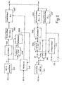
- the diagram of the transmitter enabling this method to be implemented is shown in the upper part of FIG. 2.
- the digital data to be transmitted is in the form of a serial binary signal ED.
- This signal is applied to a serial-parallel converter 201 which makes it possible to obtain at its output the words M formed from m eb.
- These words are first of all applied to a differential encoder 202 which makes it possible to deliver the control signals from a modulator 203.
- This modulator delivers under the control of these signals a carrier modulated in phase according to a set of n distinct phase states ⁇ 1 to ⁇ n ; n being equal to 2 m .
- the words M at the output of the converter 201 are also applied to comparison means which compare each word M t + 1 with the preceding word M.
- These comparison means comprise for example a delay circuit 206 which delays each word by a duration equal to a significant interval, and a comparator 204 which receives the word thus delayed and that coming directly from the converter 201. If these words are equal, comparator 204 delivers a logic "1" at its output.
- the binary operating signal ES is applied to a memory 205 of the type known as FIFO, which makes it possible to preserve the eb of this signal between the moments when it is not possible to transmit them because the signal ED does not not allow it.
- comparator 204 The logic “1" at the output of comparator 204 is applied to this memory 205. It then releases an eb from it when therefore the signal ED allows transmission.
- This modulator makes it possible to modulate this carrier by phase 0 if the eb at output of memory 205 is a logical "1". In this case the transmission of the carrier is purely and simply interrupted. This modulator therefore functions as a simple switch.
- this eb supplied by the memory 205 is a logical "0"
- the carrier leaving the modulator 203 is purely and simply transmitted.
- a first test step which consists in checking whether the phase of the signal received at time t + 1, ie ⁇ t + 1 , is equal to ⁇ 0 . If this is the case, we then pass to two simultaneous stages where we validate on the one hand the reception of an auxiliary eb BA which is equal to l, and where on the other hand we validate the reception of a word M t + 1 which is equal to M t . After these two simultaneous steps, we pass to an end step where the next significant instant t + 2 becomes the instant t + 1, which allows to start again from the flowchart.
- the receiver of the radio beam which allows to receive this modulation is shown at the bottom in Figure 2.
- the PM modulated carrier transmitted by the transmitter is received in the receiver on two demodulators.
- a first demodulator 303 of standard type makes it possible to deliver a signal which can take eight states depending on whether the phase of the carrier received has one of the eight phases 1 to n. This signal is transmitted to a decoder 302 which reconstructs words of m bits in parallel. These words are transmitted directly by a multiple "AND" gate 310 if the state ⁇ 0 has not been received.
- the words at the output of the decoder 302 are also applied to a delay device 308, formed for example of a register parallel to a stage, and which makes it possible to delay them by a significant interval.
- the word previously transmitted is available at the output of this delay device 308. If then the state ⁇ P 0 has been transmitted, indicating that the word transmitted is the same as the previous word, this delayed previous word is transmitted via a second "AND" gate 311 whose output is in parallel with that of door 310.
- the PM modulated carrier received is also applied to a demodulator 307 which makes it possible to detect the state ⁇ 0 .
- a simple detector provided for example with a threshold circuit making it possible to determine the drop in the level of the signal received below a determined value, provides a logic signal which indicates the appearance of this state ITA 0 in the received signal.
- the signal at the output of this demodulator 307 is firstly applied to the gate 310 on an inverting input, which makes it possible to open the latter when the state ⁇ 0 is not received and to close it in the case reverse.
- door 311 It is also applied to a direct entry of door 311, which allows, unlike door 310, to keep it closed when the state l'mony 0 is not received but not against opening it when we detect the presence of this state. This allows as we saw above to let pass the direct word or the delayed word when the latter is the same as the direct word and that one received ⁇ 0 .
- the output of demodulator 307 is used for states 1 directly, since the transmission of the state ⁇ 0 precisely indicates the transmission of a servitude eb of value 1.
- the input and output of the delay device 308 are applied to a multiple comparator 312.
- the comparator will detect this identity and send an eb which can for example be 0, it being understood that the comparator state 1 of rest will not mean the transmission of a service eb 1.
- Another solution could finally consist in memorizing the service eb received, and then transmitting them asynchronously with a header when there is a sufficient number.
- the probabilistic calculation shows that the auxiliary flow can reach 2.2 mega eb per second.
Landscapes
- Engineering & Computer Science (AREA)
- Computer Networks & Wireless Communication (AREA)
- Signal Processing (AREA)
- Digital Transmission Methods That Use Modulated Carrier Waves (AREA)
- Control Of Motors That Do Not Use Commutators (AREA)
- Detection And Prevention Of Errors In Transmission (AREA)
- Amplifiers (AREA)
- Circuits Of Receivers In General (AREA)
Abstract
L'invention concerne les faisceaux hertziens numériques. Elle consiste à transmettre les signaux de service d'un tel faisceau hertzien en modulant la porteuse selon un état supplémentaire dans un modulateur spécialisé (207) lorsque deux mots de donnée successifs sont identiques. A la réception un démodulateur spécialisé (307) décèle la transmission d'un eb de service ayant une valeur 1. La transmission d'un eb de service ayant une valeur 0 se fait par la détection dans un comparateur (312) de la transmission de deux mots de donnée successifs identiques, simultanément avec la détection de la non transmission de l'état supplémentaire. Cet état supplémentaire de modulation correspond avantageusement à la suppression de la porteuse. Elle permet de transmettre les signaux de service d'un tel faisceau hertzien sans augmenter le débit numérique.The invention relates to digital radio-relay systems. It consists in transmitting the service signals of such a radio beam by modulating the carrier according to an additional state in a specialized modulator (207) when two successive data words are identical. On reception a specialized demodulator (307) detects the transmission of a service eb having a value 1. The transmission of a service eb having a value 0 is made by the detection in a comparator (312) of the transmission of two identical successive data words, simultaneously with the detection of the non-transmission of the additional state. This additional state of modulation advantageously corresponds to the suppression of the carrier. It allows the service signals of such a radio beam to be transmitted without increasing the digital bit rate.
Description
La présente invention se rapporte aux procédés de transmission des signaux d'exploitation d'un faisceau hertzien numérique. Elle concerne également les émetteurs et les récepteurs qui permettent de mettre en oeuvre un tel procédé dans ces faisceaux hertziens.The present invention relates to methods for transmitting signals for operating a digital radio-relay system. It also relates to the transmitters and the receivers which make it possible to implement such a method in these radio-relay systems.
Pour exploiter un faisceau hertzien, il est nécessaire de transmettre sur ce faisceau lui-même non seulement les signaux tels que la parole, auquel il est destiné, mais encore un certain nombre de signaux annexes tels que des voies de service ou de télésurveillance. Ces signaux annexes sont couramment appelés signaux d'exploitation.To operate a radio beam, it is necessary to transmit on this beam itself not only the signals such as speech, for which it is intended, but also a certain number of auxiliary signals such as service channels or remote monitoring. These ancillary signals are commonly called operating signals.
Lorsque la modulation transmise par les faisceaux hertziens était analogique, ces signaux d'exploitation se présentaient le plus souvent sous la forme de tonalités elles-mêmes analogiques.When the modulation transmitted by the radio-relay systems was analog, these operating signals were most often in the form of tones which were themselves analog.
Dans les faisceaux hertziens dits numériques,où l'on module directement la porteuse selon un certain nombre d'états sélectionnés de manière numérique à partir de signaux d'entrée eux-mêmes numériques et pouvant représenter aussi bien des données que de la parole, il est à la. fois plus simple et plus intéressant d'utiliser ces signaux d'exploitation sous la forme de signaux numériques.In so-called digital radio-relay systems, where the carrier is directly modulated according to a certain number of states selected digitally from input signals which are themselves digital and which can represent both data and speech, there is at the. times simpler and more interesting to use these operating signals in the form of digital signals.
Pour transmettre ces signaux d'exploitation, on peut tout d'abord les multiplexer avec le signal principal à transmettre, puis transmettre la trame ainsi obtenue et la démultiplexer à la réception pour séparer les signaux d'exploitation ainsi transmis. Ceci présente l'inconvénient d'augmenter le débit du faisceau hertzien, et de nécessiter l'emploi à l'émission d'un multiplexeur et à la réception d'un démultiplexeur, qui sont des organes coûteux et encombrants.To transmit these operating signals, we can first multiplex them with the main signal to be transmitted, then transmit the frame thus obtained and demultiplex it on reception to separate the operating signals thus transmitted. This has the drawback of increasing the speed of the radio beam, and of requiring the use on the transmission of a multiplexer and on the reception of a demultiplexer, which are expensive and bulky members.
On sait également transmettre ces signaux d'exploitation sans augmenter le débit en superposant une modulation analogique, qui peut être de phase, de fréquence, ou d'amplitude, à la modulation principale apportée par le train de signaux numériques. Pour qu'une telle superposition de modulation ne perturbe pas la transmission principale, il faut se limiter à une capacité de signaux d'exploitation relativement faible.It is also known to transmit these operating signals without increasing the bit rate by superimposing an analog modulation, which may be of phase, frequency, or amplitude, on the main modulation provided by the train of digital signals. So that such a modulation overlay does not disturb the main transmission, it is necessary to limit to a relatively low operating signal capacity.
Pour transmettre ces signaux avec un débit assez important sans trop modifier le spectre d'émission, et sans utiliser trop de matériel, l'invention propose un procédé de transmission des signaux d'exploitation d'un faisceau hertzien numérique, du type consistant à transmettre des mots de donnée de m eb (m entier supérieur à 1) en modulant une porteuse selon n=2 états, caractérisé en ce que l'on transmet les signaux d'exploitation eb par eb au moyen d'un n plus unième état de la porteuse pouvant être émis à la place de l'état correspondant à un mot de donnée lorsque celui-ci est identique au précédent.To transmit these signals with a fairly large bit rate without modifying the emission spectrum too much, and without using too much equipment, the invention proposes a method of transmitting the signals for operating a digital radio-relay system, of the type consisting in transmitting data words of m eb (m integer greater than 1) by modulating a carrier according to n = 2 states, characterized in that the operating signals eb are transmitted by eb by means of an n plus first state of the carrier can be emitted in place of the state corresponding to a data word when the latter is identical to the previous one.
D'autres particularités et avantages de l'invention apparaîtront clairement dans la description suivante présentée à titre d'exemple non limitatif et faite en regard des figures annexées suivantes :
- - la figure 1, qui représente un ordinogramme de l'émission des signaux ;
- - la figure 2, qui représente le schéma d'un émetteur/récepteur de faisceau hertzien ;
- - la figure 3, qui représente un ordinogramme de la réception des signaux.
- - Figure 1, which shows a flow chart of the transmission of signals;
- - Figure 2, which shows the diagram of a radio beam transmitter / receiver;
- - Figure 3, which shows a flow chart of the reception of signals.
Dans un faisceau hertzien numérique, le signal à transmettre se présente sous la forme d'une série de mots numériques formés chacun de m éléments binaires, dont l'abréviation est le terme eb. Ces mots servent à sélectionner dans les circuits de l'émetteur du faisceau hertzien les états de la porteuse à l'émission. Ces états sont au nombre de n = 2m. C'est ainsi que pour des mots de trois eb, on peut avoir une porteuse présentant huit états de phase espacés de 45°.In a digital radio-relay system, the signal to be transmitted is in the form of a series of digital words each formed by m binary elements, the abbreviation of which is the term eb. These words are used to select in the circuits of the radio beam transmitter the carrier states on transmission. These states are n = 2 m . Thus for words of three eb, one can have a carrier having eight phase states spaced 45 ° apart.
Lorsque le signal à transmettre est formé d'une série de mots de même valeur, la phase de la porteuse reste constante. On peut alors considérer que dans ce cas le canal de transmission est inactif puisque l'on répéte la même information.When the signal to be transmitted is formed by a series of words of the same value, the carrier phase remains constant. We can then consider that in this case the transmission channel is inactive since the same information is repeated.
Selon l'invention, on transmet à ces instants les signaux d'exploitation en utilisant un état supplémentaire de la porteuse et un codage tel qu'il y ait une prédiction de la répétition du mot du signal principal. Dans ces conditions le débit en ligne n'est pas augmenté car ceci revient à substituer à un eb principal un eb auxiliaire. Par contre le nombre d'états significatifs de la portèuse est augmenté de une unité.According to the invention, the operating signals are transmitted at these times using an additional state of the carrier and a coding such that there is a prediction of the repetition of the word of the main signal. Under these conditions the online speed is not increased as this amounts to substitute a main eb for an auxiliary eb. However, the number of significant states of the portal is increased by one.
La qualité de la transmission des signaux d'exploitation n'a pas besoin d'être nécessairement aussi bonne que celle des signaux principaux. On peut alors choisir l'état supplémentaire de la porteuse de manière à modifier très peu les caractéristiques du signal émis et à faciliter tant la modulation que la démodulation au prix d'une sureté un peu plus faible de la transmission des signaux d'exploitation.The quality of the transmission of the operating signals need not necessarily be as good as that of the main signals. It is then possible to choose the additional state of the carrier so as to modify the characteristics of the transmitted signal very little and to facilitate both the modulation and the demodulation at the cost of a slightly lower security of the transmission of the operating signals.
Tous les systèmes de modulation reviennent à répartir régulièrement dans le plan de phase les points représentatifs des états de la porteuse. C'est ainsi que dans une modulation purement de phase ces points représentatifs sont régulièrement répartis sur un cercle centré sur l'origine des axes, et que dans le cas d'une modulation par états, qui correspond en fait à la superposition d'une modulation d'amplitude et d'une modulation de phase, ils sont répartis sur un quadrillage lui-même centré sur l'origine des axes. Dans tous ces cas on n'utilise généralement pas l'état zéro, qui correspond à l'origine des axes, parce que celui-ci correspond à une suppression de la porteuse qui augmente l'incidence des signaux parasites et donc les risques de faux décodages.All the modulation systems amount to regularly distributing in the phase plane the points representative of the states of the carrier. Thus in a purely phase modulation these representative points are regularly distributed on a circle centered on the origin of the axes, and that in the case of a modulation by states, which corresponds in fact to the superposition of a amplitude modulation and phase modulation, they are distributed over a grid itself centered on the origin of the axes. In all these cases, the zero state is generally not used, which corresponds to the origin of the axes, because this corresponds to a suppression of the carrier which increases the incidence of parasitic signals and therefore the risks of false decodings.
Une bonne solution pour le choix de l'état supplémentaire pour la transmission des signaux d'exploitation, consiste justement à utiliser cet état zéro qui est plus sensible aux parasites, mais perturbe très peu la transmission.A good solution for the choice of the additional state for the transmission of the operating signals, consists precisely in using this zero state which is more sensitive to parasites, but disturbs the transmission very little.
Si donc un mot à transmettre Mt+1 est identique au mot M correspondant à l'instant significatif précédent, l'état de la porteuse à transmettre sera alors normalement φt+1 = φt. Pour pouvoir alors transmettre pendant cet intervalle significatif t+1 la valeur de l'eb du signal d'exploitation, on choisira un codage qui consistera par exemple à transmettre l'état φ0 de la porteuse si cet eb a pour valeur 1, et l'était φt si cet eb à la valeur zéro.If therefore a word to be transmitted Mt + 1 is identical to the word M corresponding to the preceding significant instant, the state of the carrier to be transmitted will then normally be φ t + 1 = φ t . In order to then be able to transmit during this significant interval t + 1 the value of the eb of the operating signal, a coding will be chosen which will consist, for example, in transmitting the state φ 0 of the carrier if this eb has the
Ce procédé de codage est représenté par l'ordinogramme de la figure 1.This coding process is represented by the flowchart in Figure 1.
Dans cet ordinogramme on part d'une étape de test sur la valeur du mot Mt+1. Si ce mot n'est pas égal à Mt , on passe à une étape d'émission de la porteuse avec la phase φt+1. On termine alors la séquence par le passage à l'instant significatif suivant où l'on fait t+2 = t+1, et il y a retour au départ.In this flowchart, we start from a test step on the value of the word M t + 1 . If this word is not equal to M t , we go to a step transmission of the carrier with the phase φ t + 1 . We then end the sequence by passing to the next significant instant where we do t + 2 = t + 1, and there is a return to the start.
Si par contre Mt+1 est égal à Mt , on passe à une deuxième séquence de test sur la valeur de l'eb d'exploitation BA. Si BA est égal à 1 ,on passe à une étape d'émission de la porteuse avec la phase φ0 puis à l'étape de fin.If on the other hand M t + 1 is equal to M t , we pass to a second test sequence on the value of the operating EB BA. If BA is equal to 1, we pass to a step of transmitting the carrier with the phase φ 0 then to the end step.
Si BA n'est pas égal à 1 on passe à l'étape d'émission de la porteuse avec la phase φt+1 ,qui dans ce cas est égale à la phase φt, et ensuite à l'étape de fin.If BA is not equal to 1, we pass to the step of transmitting the carrier with the phase φ t + 1 , which in this case is equal to the phase φ t , and then to the end step.
Le schéma de l'émetteur permettant de mettre en oeuvre cette méthode est représenté sur la partie haute de la figure 2.The diagram of the transmitter enabling this method to be implemented is shown in the upper part of FIG. 2.
Les données numériques à transmettre se présentent sous la forme d'un signal binaire série ED. Ce signal est appliqué à un convertisseur série-parallèle 201 qui permet d'obtenir à sa sortie les mots M formés de m eb. Ces mots sont tout d'abord appliqués à un codeur différentiel 202 qui permet de délivrer les signaux de commande d'un modulateur 203.The digital data to be transmitted is in the form of a serial binary signal ED. This signal is applied to a serial-
Ce modulateur délivre sous la commande de ces signaux une porteuse modulée en phase selon un ensemble de n états de phase distincts φ1 à φn; n étant égal à 2m.This modulator delivers under the control of these signals a carrier modulated in phase according to a set of n distinct phase states φ 1 to φ n ; n being equal to 2 m .
Les mots M en sortie du convertisseur 201 sont également appliqués à des moyens de comparaison qui comparent chaque mot Mt+1 au mot M précédent. Ces moyens de comparaison comprennent par exemple un circuit de retard 206 qui retarde chaque mot d'une durée égale à un intervalle significatif, et un comparateur 204 qui reçoit le mot ainsi retardé et celui provenant directement du convertisseur 201. Si ces mots sont égaux, le comparateur 204 délivre sur sa sortie un "1" logique. Le signal binaire d'exploitation ES est appliqué à une mémoire 205 du type connu sous le nom de FIFO,qui permet de conserver les eb de ce signal entre les instants où il n'est pas possible de les transmettre parce que le signal ED ne le permet pas.The words M at the output of the
Le "1" logique en sortie du comparateur 204 est appliqué à cette mémoire 205. Il libère alors un eb de celle-ci lorsque donc le signal ED permet la transmission.The logic "1" at the output of
La sortie de cette mémoire est reliée à l'entrée de modulation d'un deuxième modulateur 207 qui reçoit d'autre part la porteuse modulée provenant du modulateur 203. Ce modulateur permet de moduler cette porteuse par la phase 0 si l'eb en sortie de la mémoire 205 est un "1" logique. Dans ce cas la transmission de la porteuse est purement et simplement interrompue. Ce modulateur fonctionne donc comme un simple interrupteur.The output of this memory is connected to the modulation input of a
Si par contre cet eb fourni par la mémoire 205 est un "0" logique, la porteuse sortant du modulateur 203 est purement et simplement transmise.If on the other hand this eb supplied by the
On obtient ainsi la porteuse PM qui est émise vers le récepteur.This gives the carrier PM which is transmitted to the receiver.
Le décodage des signaux à la réception s'effectue selon l'ordinogramme représenté sur la figure 3.The decoding of the signals on reception is carried out according to the flowchart shown in Figure 3.
On part d'une première étape de test qui consiste à vérifier si la phase du signal reçu à l'instant t+1, soit φt+1, est égale à φ0. Si c'est le cas on passe ensuite à deux étapes simultanées où l'on valide d'une part la réception d'un eb auxiliaire BA qui est égal à l, et où d'autre part on valide la réception d'un mot Mt+1 qui est égal à Mt. Après ces deux étapes simultanées, on passe à une étape de fin où l'instant significatif suivant t+2 devient l'instant t+1, ce qui permet de repartir au départ de l'ordinogramme.We start from a first test step which consists in checking whether the phase of the signal received at time t + 1, ie φ t + 1 , is equal to φ 0 . If this is the case, we then pass to two simultaneous stages where we validate on the one hand the reception of an auxiliary eb BA which is equal to l, and where on the other hand we validate the reception of a word M t + 1 which is equal to M t . After these two simultaneous steps, we pass to an end step where the next significant instant t + 2 becomes the instant t + 1, which allows to start again from the flowchart.
Si φt+1 n'est pas égal à 0 on passe alors dans une deuxième étape de test où l'on vérifie si φt+1 est égal à φt.If φ t + 1 is not equal to 0 then we go to a second test step where we check if φ t + 1 is equal to φ t .
Si c'est le cas on passe alors dans deux étapes simultanées, dont l'une correspond à la réception d'un mot Mt+1 qui est égal au mot précédent Mt. Cette étape est commune à l'une de la branche précédente. L'autre étape correspond à la réception d'un eb auxiliaire BA qui est égal à 0.If this is the case, we then go through two simultaneous steps, one of which corresponds to the reception of a word M t + 1 which is equal to the previous word M t . This step is common to one of the previous branch. The other step corresponds to the reception of an auxiliary eb BA which is equal to 0.
Si φ t+1 est différent de t , on passe à une étape unique correspondant à la réception d'un mot Mt+1 déterminé par la phase φt+1.If φ t + 1 is different from t, we pass to a single step corresponding to the reception of a word M t + 1 determined by the phase φ t + 1 .
Dans les deux cas on passe à l'étape de fin qui permet de repartir au départ.In both cases we go to the end stage which allows us to start again at the start.
Le récepteur du faisceau hertzien qui permet de recevoir cette modulation est représenté en partie basse sur la figure 2.The receiver of the radio beam which allows to receive this modulation is shown at the bottom in Figure 2.
La porteuse modulée PM émise par l'émetteur est reçue dans le récepteur sur deux démodulateurs.The PM modulated carrier transmitted by the transmitter is received in the receiver on two demodulators.
Un premier démodulateur 303 de type standard permet de délivrer un signal pouvant prendre huit états selon que la phase de la porteuse reçue présente l'une des huit phases 1 à n. Ce signal est émis vers un décodeur 302 qui reconstitue des mots de m bits en parallèle. Ces mots sont transmis directement par une porte "ET" multiple 310 si l'état φ 0 n'a pas été reçu.A
Les mots en sortie du décodeur 302 sont également appliqués à un dispositif de retard 308, formé par exemple d'un registre parallèle à un étage, et qui permet de les retarder d'un intervalle significatif. On dispose à la sortie de ce dispositif de retard 308 du mot précédemment transmis. Si alors l'état <P 0 a été transmis, indiquant que le mot transmis est le même que le mot précédent, ce mot précédent retardé est transmis par l'intermédiaire d'une deuxième porte "ET" 311 dont la sortie est en parallèle avec celle de la porte 310.The words at the output of the
Ces deux sorties en parallèle sont alors appliquées à un convertisseur parallèle-série 301 qui permet de délivrer le signal de donnée reçu en mode série. Ce signal RD est donc identique, aux erreurs éventuelles de transmission près, au signal émis ED.These two outputs in parallel are then applied to a parallel-
La porteuse modulée PM reçue est également appliquée à un démodulateur 307 qui permet de détecter l'état φ0. Comme cet état dans l'exemple décrit est simplement composé d'une absence de la porteuse, un simple détecteur, muni par exemple d'un circuit à seuil permettant de déterminer la chute du niveau du signal reçu en dessous d'une valeur déterminée, permet de délivrer un signal logique qui indique l'apparition de cet état φ0 dans le signal reçu.The PM modulated carrier received is also applied to a
Le signal en sortie de ce démodulateur 307 est d'une part appliqué à la porte 310 sur une entrée inverseuse, ce qui permet d'ouvrir celle-ci lorsque l'état φ0 n'est pas reçu et de la fermer dans le cas inverse.The signal at the output of this
Il est également appliqué à une entrée directe de la porte 311, ce qui permet, à l'inverse de la porte 310, de la maintenir fermée lorsque l'état φ0 n'est pas reçu mais pas contre de l'ouvrir lorsqu'on décèle la présence de cet état. Ceci permet comme on l'a vu plus haut de laisser passer le mot direct ou le mot retardé lorsque ce dernier est le même que le mot direct et que l'on a reçu φ0.It is also applied to a direct entry of
Pour obtenir le signal numérique de servitude, on utilise pour les états 1 directement la sortie du démodulateur 307, puisque la transmission de l'état φ0 indique justement la transmission d'un eb de servitude de valeur 1.To obtain the digital servitude signal, the output of
Quand par contre l'état φ0 n'est pas transmis, on ne peut pas interpréter l'absence de signal en sortie du démodulateur 307 comme la transmission d'un eb de service de valeur 0.When, on the other hand, the state φ 0 is not transmitted, the absence of signal at the output of the
Le test de cette transmission se fait comme on l'a vu plus haut sur la transmission de deux mots de donnée successifs de même valeur obtenus par la transmission successive de deux états identiques choisis entre 1 et φn.The test of this transmission is done as we saw above on the transmission of two successive data words of the same value obtained by the successive transmission of two identical states chosen between 1 and φ n .
Pour déterminer cela on applique à un comparateur multiple 312 l'entrée et la sortie du dispositif de retard 308. Ainsi si les mots transmis à deux instants significatifs successifs sont les mêmes, le comparateur détectera cette identité et émettra sur sa sortie un eb qui pourra être par exemple 0, étant bien entendu que l'état 1 de repos du comparateur ne signifira pas la transmission d'un eb de service 1.To determine this, the input and output of the
On voit donc que pour obtenir les eb de service, il faut au moins deux sorties distinctes, l'une pour les eb 1, l'autre pour les eb 0, parce que la transmission ne se fait pas en permanence. Les circuits de servitude fonctionnant à partir de ces eb interpréteront les signaux présents sur ces deux sorties. On pourrait aussi reconstituer un train binaire série formé de 1 et de 0 pour les eb de servitude à l'intérieur du récepteur proprement dit, de façon à disposer de ces eb sur une seule sortie. Mais il faudrait alors une autre sortie comportant un signal de validation pour distinguer l'absence de signal sur la première sortie de la transmission d'un eb 0. On aurait alors toujours deux sorties.It can therefore be seen that to obtain the service eb, at least two separate outputs are required, one for
Une autre solution pourrait enfin consister à mettre en mémoire les eb de service reçus, et à les transmettre ensuite de manière asynchrone avec un en-tête lorsqu'on en aurait un nombre suffisant.Another solution could finally consist in memorizing the service eb received, and then transmitting them asynchronously with a header when there is a sufficient number.
Pour savoir quel est le débit maximal des eb de service disponible, il faut se placer dans le cas où le signal de donnée est aléatoire. C'est d'ailleurs le cas général puisque l'on utilise le plus souvent un brouilleur à l'émission et un débrouilleur à la réception afin de minimiser le risque d'erreur, conformément à la théorie de l'information, et d'avoir un nombre suffisant de transitions dans le signal.To find out what is the maximum speed of service eb available, it must be placed in the case where the data signal is random. This is also the general case since we most often use a jammer on transmission and a scrambler on reception in order to minimize the risk of error, in accordance with information theory, and have a sufficient number of transitions in the signal.
Dans ce cas, en partant d'un débit principal de 140 méga eb par seconde, et pour un modulateur à huit phases, le calcul probabiliste montre que le débit auxiliaire peut atteindre 2,2 méga eb par seconde.In this case, starting from a main flow of 140 mega eb per second, and for an eight-phase modulator, the probabilistic calculation shows that the auxiliary flow can reach 2.2 mega eb per second.
On ne peut toutefois pas se permettre de monter à ce débit pour les eb de service, puisqu'ils apparaissent de manière continue alors que la probabilité de transmission due à la présence de deux mots consécutifs identiques est aléatoire. Pour ne pas perdre trop de mots, on peut utiliser par exemple un système de suréchantillonnage, qui consiste à retransmettre en moyenne plusieurs fois le même eb auxiliaire.We cannot, however, afford to go up to this speed for the service ebs, since they appear continuously while the probability of transmission due to the presence of two identical consecutive words is random. In order not to lose too many words, one can use for example an oversampling system, which consists in retransmitting on average several times the same auxiliary eb.
En reprenant l'exemple numérique vu plus haut, si l'on désire avoir un débit auxiliaire égal à 300 kilobits par seconde, ce qui représente un suréchantillonnage de 7,3 fois, le calcul de probabilité montre que le risque de perte d'un eb auxiliaire, et donc de déverrouillage des circuits auxiliaires, aura une valeur de 10-34, ce qui est très faible et parfaitement acceptable.Using the numerical example seen above, if one wishes to have an auxiliary flow rate equal to 300 kilobits per second, which represents an oversampling of 7.3 times, the probability calculation shows that the risk of losing a auxiliary eb, and therefore unlocking of the auxiliary circuits, will have a value of 10 -34 , which is very low and perfectly acceptable.
Claims (8)
Applications Claiming Priority (2)
| Application Number | Priority Date | Filing Date | Title |
|---|---|---|---|
| FR8024802 | 1980-11-21 | ||
| FR8024802A FR2494938A1 (en) | 1980-11-21 | 1980-11-21 | METHOD FOR TRANSMITTING THE OPERATING SIGNALS OF A DIGITAL RADIO BEAM, TRANSMITTER AND RECEIVER FOR IMPLEMENTING SUCH A METHOD |
Publications (2)
| Publication Number | Publication Date |
|---|---|
| EP0053051A1 true EP0053051A1 (en) | 1982-06-02 |
| EP0053051B1 EP0053051B1 (en) | 1985-01-16 |
Family
ID=9248249
Family Applications (1)
| Application Number | Title | Priority Date | Filing Date |
|---|---|---|---|
| EP81401635A Expired EP0053051B1 (en) | 1980-11-21 | 1981-10-16 | Method of transmitting operational signals of a digital microwave link; transmitter and receiver for carrying out such a method |
Country Status (5)
| Country | Link |
|---|---|
| US (1) | US4426711A (en) |
| EP (1) | EP0053051B1 (en) |
| JP (3) | JPS57112160A (en) |
| DE (1) | DE3168370D1 (en) |
| FR (1) | FR2494938A1 (en) |
Families Citing this family (2)
| Publication number | Priority date | Publication date | Assignee | Title |
|---|---|---|---|---|
| CA2015105C (en) * | 1989-04-21 | 1994-07-26 | Toshio Mizuno | Hybrid modulation satellite communication system |
| GB2307152B (en) * | 1995-11-10 | 1999-04-07 | Motorola Ltd | Method and apparatus for enhanced communication capability while maintaining standard channel modulation compatibility |
Family Cites Families (1)
| Publication number | Priority date | Publication date | Assignee | Title |
|---|---|---|---|---|
| JPS5147311A (en) * | 1974-10-22 | 1976-04-22 | Fujitsu Ltd | Ai araamuhensohoshiki |
-
1980
- 1980-11-21 FR FR8024802A patent/FR2494938A1/en active Granted
-
1981
- 1981-10-16 DE DE8181401635T patent/DE3168370D1/en not_active Expired
- 1981-10-16 EP EP81401635A patent/EP0053051B1/en not_active Expired
- 1981-11-06 US US06/318,797 patent/US4426711A/en not_active Expired - Fee Related
- 1981-11-20 JP JP56185596A patent/JPS57112160A/en active Pending
-
1988
- 1988-06-22 JP JP63152451A patent/JPS6446353A/en active Granted
- 1988-06-22 JP JP63152450A patent/JPS6446352A/en active Granted
Non-Patent Citations (2)
| Title |
|---|
| ELECTRONICS, vol. 43, no. 11, mai 1970 New York, US "On the air with microwave PCM" page 91 * |
| IEEE TRANSACTIONS ON COMMUNICATIONS vol. COM-27, no. 12, décembre 1979 New York, US THOMAS et al.: "A New Generation of Digital Microwave Radios for U.S. Military Telephone Networks", pages 1916-1927 * |
Also Published As
| Publication number | Publication date |
|---|---|
| FR2494938B1 (en) | 1984-03-02 |
| JPS6446353A (en) | 1989-02-20 |
| JPS57112160A (en) | 1982-07-13 |
| EP0053051B1 (en) | 1985-01-16 |
| DE3168370D1 (en) | 1985-02-28 |
| FR2494938A1 (en) | 1982-05-28 |
| JPS6446352A (en) | 1989-02-20 |
| JPH0243387B2 (en) | 1990-09-28 |
| US4426711A (en) | 1984-01-17 |
| JPH0243388B2 (en) | 1990-09-28 |
Similar Documents
| Publication | Publication Date | Title |
|---|---|---|
| EP0192061B1 (en) | Device for automatic gain control in a tdma receiver | |
| EP0013343B1 (en) | Process and device to detect a pseudo-random sequence of 0 degree and 180 degree phase changes of the carrier in a data receiver | |
| EP0863635B1 (en) | Method and device for transmitting data frames | |
| FR2602938A1 (en) | Subscriber unit for wireless digital telephone; modem and diverse devices (frequency synthesizer etc.) for this unit | |
| FR2496363A1 (en) | METHOD AND DEVICE FOR DETECTING THE LEARNING SEQUENCE OF A SELF-ADAPTIVE EQUALIZER | |
| FR2512295A1 (en) | STEREOPHONIC RECEIVER WITH MULTI-SYSTEM AMPLITUDE MODULATION | |
| EP0090728B1 (en) | Process for transmitting a hdbn coded signal with an auxiliary binary signal, coder and decoder according to the process and remote repeater supervision of a digital link by such an auxiliary signal | |
| FR2736231A1 (en) | DIGITAL COMMUNICATION SYSTEM COMPRISING A RECEIVER HAVING A RHYTHM RECOVERY DEVICE | |
| EP0018242A1 (en) | Method and device for stochastic demodulation of phase-shift keyed signals working in time division on several channels | |
| EP0018256B1 (en) | Transceiver with automatic switch-over control, and telecommunications network comprising such a transceiver | |
| EP0053051B1 (en) | Method of transmitting operational signals of a digital microwave link; transmitter and receiver for carrying out such a method | |
| FR2491419A1 (en) | AUTOMATIC TRAIN CONTROL APPARATUS | |
| EP0064923B1 (en) | System for the phase synchronization of digital data streams, and its application to the commutation of said data streams | |
| FR2661579A1 (en) | DEVICE FOR PHASING SIGNALS IN A DIGITAL DUCT SYSTEM. | |
| EP0097753A1 (en) | Tone receiver for a digital data transmission system | |
| EP0288353B1 (en) | Method for switching asyschronous digital signals, and device for carrying out this method | |
| CA2060413C (en) | Interfering signal detection method and device for a digital data demodulator | |
| FR2621132A1 (en) | Method and device for measuring distances | |
| CA2358719C (en) | Broadcasting system, and process ensuring the continuity of service | |
| EP0660561B1 (en) | Circuit for recognition of a sequence of words in a modem | |
| EP0011014A1 (en) | Device for measuring the quality of a digital connection and transmission equipments including such a device | |
| EP0322059B1 (en) | Sound scrambling/descrambling system and method | |
| FR2481029A1 (en) | Receive and transmit path supervision in diversity system - uses data channel telegrams to carry out line checking | |
| EP0184953A1 (en) | Method and device for digital information transmission using differential frequency shift keying | |
| FR2673497A1 (en) | METHOD FOR REALIZING PROTECTED TRANSMISSION OF RADIO ELECTRIC SIGNALS |
Legal Events
| Date | Code | Title | Description |
|---|---|---|---|
| PUAI | Public reference made under article 153(3) epc to a published international application that has entered the european phase |
Free format text: ORIGINAL CODE: 0009012 |
|
| AK | Designated contracting states |
Designated state(s): DE GB IT |
|
| 17P | Request for examination filed |
Effective date: 19821028 |
|
| ITF | It: translation for a ep patent filed | ||
| GRAA | (expected) grant |
Free format text: ORIGINAL CODE: 0009210 |
|
| AK | Designated contracting states |
Designated state(s): DE GB IT |
|
| REF | Corresponds to: |
Ref document number: 3168370 Country of ref document: DE Date of ref document: 19850228 |
|
| PLBE | No opposition filed within time limit |
Free format text: ORIGINAL CODE: 0009261 |
|
| STAA | Information on the status of an ep patent application or granted ep patent |
Free format text: STATUS: NO OPPOSITION FILED WITHIN TIME LIMIT |
|
| 26N | No opposition filed | ||
| PGFP | Annual fee paid to national office [announced via postgrant information from national office to epo] |
Ref country code: DE Payment date: 19880811 Year of fee payment: 8 |
|
| PG25 | Lapsed in a contracting state [announced via postgrant information from national office to epo] |
Ref country code: GB Effective date: 19891016 |
|
| GBPC | Gb: european patent ceased through non-payment of renewal fee | ||
| PG25 | Lapsed in a contracting state [announced via postgrant information from national office to epo] |
Ref country code: DE Effective date: 19900703 |