EP0863524B1 - Commutateur pour sectionneur à cinq poles à usage d'inverseur de phases - Google Patents
Commutateur pour sectionneur à cinq poles à usage d'inverseur de phases Download PDFInfo
- Publication number
- EP0863524B1 EP0863524B1 EP98400458A EP98400458A EP0863524B1 EP 0863524 B1 EP0863524 B1 EP 0863524B1 EP 98400458 A EP98400458 A EP 98400458A EP 98400458 A EP98400458 A EP 98400458A EP 0863524 B1 EP0863524 B1 EP 0863524B1
- Authority
- EP
- European Patent Office
- Prior art keywords
- switches
- contact
- levers
- contacts
- lever
- Prior art date
- Legal status (The legal status is an assumption and is not a legal conclusion. Google has not performed a legal analysis and makes no representation as to the accuracy of the status listed.)
- Expired - Lifetime
Links
Images
Classifications
-
- H—ELECTRICITY
- H01—ELECTRIC ELEMENTS
- H01H—ELECTRIC SWITCHES; RELAYS; SELECTORS; EMERGENCY PROTECTIVE DEVICES
- H01H21/00—Switches operated by an operating part in the form of a pivotable member acted upon directly by a solid body, e.g. by a hand
- H01H21/54—Lever switches with blade-type contact co-operating with one or two spring-clip contacts, e.g. knife switch
- H01H21/58—Change-over switches without stable intermediate position
Definitions
- the invention relates to current disconnectors comprising five switches used as phase inverters in a three-phase system, for example for pumping units where the alternator becomes the engine so to obtain the reversal of the direction of rotation of the rotary machine.
- phase reversing disconnector comprising five switches is known in particular from US patent document 4 357 502.
- the device requires the use of two control systems coupled to a shaft transmission.
- a first lever is permanently integral in rotation with the shaft transmission, and can be operated by a main control system reversible to two positions.
- An auxiliary control system operates like a two-position clutch for selectively transmitting the torque from the drive shaft to either of two other levers which are each connected to a pair of switches by a connecting rod system.
- the assembly thus produced is relatively bulky and requires a coordination of the main control system with the auxiliary system Clutch.
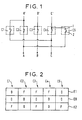
- FIG. 1 shows a classic block diagram of such a disconnector phase inverter comprising five switches C1 to C5.
- the disconnector is connected between three phase inputs indicated respectively by A, B, C and three phase outputs indicated respectively by A ', B', C '.
- Each switch comprises a first fixed contact 1 and a second contact 2 which cooperates with the first contact.
- the second contact 2 is mobile to occupy a first position according to which it is electrically connected to the fixed contact (see switches C2, C3, C4) and a second position according to which it is separated of the fixed contact (see switches C1 and C5).
- the movable contacts 2 of the switches C1 and C4 are electrically connected to the phase input C
- the movable contacts 2 C2 and OS switches are electrically connected to phase A input
- the movable contact 2 of the switch C3 is connected to the phase input B.
- the fixed contacts 1 of switches C1 and C2 are connected electrically at the phase output A '
- the fixed contacts 1 of the switches C4 and OS are electrically connected to the phase output C 'and the fixed contact 1 of the switch C3 is electrically connected to phase output B '.
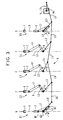
- this disconnector for phase inverter is summarized in the table of FIG. 2.
- switches C1 and C5 are open (these switches being in the position indicated by O) and the switches C2 to C4 are closed (these switches being in the position indicated by F).
- phase A input is electrically connected to phase output A '
- the input of phase B is electrically connected to phase output B '
- phase input C is electrically connected to the phase output C '.
- switches C1 to C5 are all open. According to this position, the inputs of the disconnector are all separated from its outputs.
- a third position E2 of the disconnector switches C1, C3 and C5 are closed and switches C2 and C4 are open.
- phase input C is electrically connected to phase output A '
- the input of phase B is electrically connected to phase output B '
- phase input A is electrically connected to the phase output C '.
- this disconnector is designed to pass from the position E1 to position E2 (or vice versa) necessarily passing through the EO position, other connection possibilities between inputs and outputs of the disconnector being prohibited.
- the object of the invention is to propose an arrangement of switches for such a disconnector for phase inverter use in which the switches are controlled by a single command while avoiding connection possibilities prohibited.
- the applicant sought to transform such a single control switching system to get a disconnector for phase inverter use for a three-phase network, knowing that two phases are inverted necessarily by passing through a position intermediate opening of all switches in the system.
- a disconnector electric comprising a plurality of electric switches which include each a first fixed contact and a second mobile contact cooperating with the fixed contact, this second contact being arranged to move by a movement in translation in a longitudinal direction between a first position in which it is connected to the fixed contact and a second position in which it is separate from the fixed contact, the movement of the second contact being ensured by the play a pair of levers hinged together in rotation, one end of the first lever being connected to the second contact via an axis of rotation movable in translation in said longitudinal direction, one end of the second lever being mounted in rotation on a fixed axis relative to the first contact, a connecting rod system comprising third integral levers respectively in rotation of the second levers, this linkage system also comprising a set of control rods articulated in rotation to the third levers and interconnected one after the other in order to connect the second lever of each switch to a single control of said connecting rod system, one of these connecting rods being connected to said control by via a
- such a switch arrangement allows to design a disconnector with five switches functioning as phase reverser with a single three-position control and a system connecting rod connecting the second levers of the switches to the control, by a judicious choice of the ratio between the linkage kinematics and the kinematics internal electrical switches.
- Figure 1 is a very schematic representation of a disconnector comprising five switches and serving as a phase inverter.
- Figure 2 summarizes in the form of a table, the operation of such phase reversing disconnector.
- Figure 3 shows schematically a disconnector with five switches according to the invention in a first position corresponding to the position E1 of the table in FIG. 2.
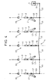
- Figure 4 shows the disconnector of Figure 3 in a second position corresponding to position E0 of the table in FIG. 2.
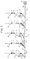
- Figure 5 shows the disconnector of Figure 3 in a third position corresponding to position E2 of the table in FIG. 2.
- FIG. 3 shows schematically five switches C1 to C5 according to the invention which form part of a so-called pentapole disconnector serving as phase inverter, similar to that shown in Figure 1, the inputs and the outputs corresponding to phases A to C and A 'to C' are however not represented
- Each switch such as C1 includes a fixed contact 1 and a contact 2 which is movable to occupy a first position according to which it is connected to fixed contact 1 (closing position F of the switch) and a second position according to which it is separated from fixed contact 1 (opening position O of the switch).
- the movable contact 2 moves between these two positions by a translational movement in a longitudinal direction of movement indicated by 3
- the translational movement in the direction 3 of the movable contact 2 is ensured by the play of a pair of levers L1 and L2. More specifically, the lever L1 has one end which is connected to contact 2 via an axis A1 of rotation mobile in translation in the longitudinal direction 3. The levers L1 and L2 are hinged together in rotation about an axis A2. The lever L2 has one end which is rotatably mounted on an axis A3 fixed relative to the contact 1.
- the relative angular displacement between the levers L1 and L2 is transformed in a translational movement of the movable contact 2, the choice of the length levers L1 and L2 and the relative angular displacement between these two levers for adjusting the stroke of the movable contact.
- a disconnector according to the invention with five switches electrics used as phase reverser includes a single control three-position rickshaw 4 mechanically connected to the switches by through a linkage system 5.
- the three-position control 4 is here an electric motor whose rotor A4 serves as a movement transmission device for the linkage system.
- the connecting rod system 5 comprises, for each switch C1, C2, C4 and C5, a lever L3 integral in rotation with the lever L2 of each switch and for switch C3 a lever L4 integral in rotation with the lever L2 of this switch.
- the operation of the linkage system 5 is as follows.
- lever L6 moves in translation the control rod L5 to which it is connected.
- the displacement of this lever L5 is transformed into an angular displacement of lever L3 associated with switch C5.
- the translational movement of this connecting rod command L5 causes the translational movement of the control rod L5 associated with switch C4, causing the translational movement of the movable contact 2 of this switch C4, and so on for the others switches C3 to C1.
- Obtaining positions E1, E0, E2 of the disconnector in accordance with table in Figure 2 is based on the ratio of the linkage kinematics and the internal kinematics of the switches, the lengths of the control rods L5 having no influence on the operation of the disconnector.
- the disconnector is shown in its position E0 in the table of the Figure 2. In this position, we see that all the movable contacts 2 of switches are separated from the fixed contacts 1.
- the levers L3 and L4 are here parallel to each other.
- the switches C1 and C5 have their levers L1 and L2 which occupy a first identical angular position.
- the levers L1 and L2 of switches C2 and C4 occupy a second identical angular position.
- the levers L1 and L2 of switch C3 occupy a third angular position intermediate to the first and second angular positions above.
- the kinematics of the levers L1 and L2 of the switch C3 is different from that of levers L1 and L2 of the switches C1, C2 and C4, C5. Furthermore, the angular position of the levers L1 and L2 of the switch C1 is symmetrical, in direction 3, at the angular position of levers L1 and L2 of switch C2.
- the lever L6 has rotated in a first direction of rotation of 90 ° relative to its position in Figure 4.
- the levers L1 and L2 of the switches C1 and C5 now occupy said second angular position so that these switches are open.
- the L2 levers of these switches have turned clockwise opposite an angle ⁇ .
- the levers L2 of the switches C2 and C4 have rotated counterclockwise by an angle ⁇ so that these switches are also in a closed position.
- the L2 lever of switch C3 has rotated counterclockwise by a larger angle ⁇ that ⁇ (because the length of the lever L4 is less than the length of the levers L3) so that this switch is in the closed position.
- the lever L6 has rotated in a second direction of rotation of 90 ° relative to its position in Figure 4.
- the levers L1 and L2 of the switches C2 and C4 now occupy said first angular position and these switches are open.
- the L2 levers of these switches have therefore turned clockwise at an angle ⁇ .
- the levers L2 of switches C1 and C5 have turned clockwise by an angle ⁇ so these switches are in closed position.
- the lever L2 of the switch C3 has turned in the direction time of an angle ⁇ so that this switch is also in a position of closing.
- the transition from position E0 to the position E1 of the disconnector is obtained by a first rotation of 90 ° of the rotor of command 4 and the transition from position E0 to position E2 is obtained by a second 90 ° rotation of the rotor of control 4 but in the direction reverse at the first rotation.
- the rotation angle of the rotor A4 can be different 90 ° (for example 30 °) but an angle of 90 ° ensures no reversibility of the transmission of the command on the move.
- the length of the rod L6 is chosen according to the power of the control 4 and the effort required to move the movable contacts 2.
- linkage system 5 can be replaced by a gear system or a cable system.
Landscapes
- Driving Mechanisms And Operating Circuits Of Arc-Extinguishing High-Tension Switches (AREA)
- Rotary Switch, Piano Key Switch, And Lever Switch (AREA)
- Breakers (AREA)
- Mechanisms For Operating Contacts (AREA)
- Waveguide Switches, Polarizers, And Phase Shifters (AREA)
- Gas-Insulated Switchgears (AREA)
- Inverter Devices (AREA)
Description
Claims (1)
- Un sectionneur électrique comprenant une pluralité de commutateurs électriques qui comportent chacun un premier contact fixe (1) et un second contact mobile (2) coopérant avec le contact fixe, ce second contact (2) étant agencé pour se déplacer par un mouvement en translation selon une direction longitudinale (3) entre une première position (F) dans laquelle il est relié au contact fixe et une seconde position (O) dans laquelle il est séparé du contact fixe, le déplacement du second contact étant assuré par le jeu d'une paire de leviers (L1, L2) articulés entre eux en rotation, une extrémité du premier levier (L1) étant reliée au second contact par l'intermédiaire d'un axe (A1) de rotation mobile en translation selon ladite direction longitudinale, une extrémité du second levier (L2) étant montée en rotation sur un axe (A3) fixe par rapport au premier contact, un système d'embiellage (5) comprenant des troisièmes leviers (L3, L4) solidaires respectivement en rotation des seconds leviers (L2), ce système (5) comprenant aussi un ensemble de bielles de commande (L5) articulées en rotation aux troisièmes leviers (L3, L4) et reliées entre elles les unes à la suite des autres afin de relier le second levier (L2) de chaque commutateurs à une commande (4) unique dudit système d'embiellage (5), l'une de ces bielles (L5) étant reliée à ladite commande (4) par l'intermédiaire d'un quatrième levier (L6), caractérisé en ce que lesdits commutateurs électriques sont au nombre de cinq et ladite commande (4) du système d'embiellage (5) est à trois positions, et en ce que pour une première position (E1) du système d'embiellage, les contacts mobiles (2) de deux commutateurs électriques (C1, C5) sont séparés de leurs contacts fixes (1) respectifs et les contacts mobiles (2) des trois autres commutateurs électriques (C2, C3, C4) sont reliés à leurs contacts fixes (1) respectifs, pour une seconde position (E0) du système d'embiellage, les contacts mobiles (2) des cinq commutateurs (C1 à C5) sont tous séparés des contacts fixes (1), et pour une troisième position (E2) du système d'embiellage, les contacts mobiles (2) de ces deux premiers commutateurs électriques (C1, C5) et le contact mobile (2) d'un (C3) des trois autres commutateurs électriques sont reliés à leurs contacts fixes (1) respectifs tandis que les contacts mobiles (2) des deux autres commutateurs électriques (C2, C4) sont séparés de leurs contacts fixes (1) respectifs.
Applications Claiming Priority (2)
| Application Number | Priority Date | Filing Date | Title |
|---|---|---|---|
| FR9702349 | 1997-02-27 | ||
| FR9702349A FR2760125B1 (fr) | 1997-02-27 | 1997-02-27 | Commutateur pour sectionneur a cinq poles a usage inverseur de phases |
Publications (2)
| Publication Number | Publication Date |
|---|---|
| EP0863524A1 EP0863524A1 (fr) | 1998-09-09 |
| EP0863524B1 true EP0863524B1 (fr) | 2004-07-21 |
Family
ID=9504243
Family Applications (1)
| Application Number | Title | Priority Date | Filing Date |
|---|---|---|---|
| EP98400458A Expired - Lifetime EP0863524B1 (fr) | 1997-02-27 | 1998-02-26 | Commutateur pour sectionneur à cinq poles à usage d'inverseur de phases |
Country Status (6)
| Country | Link |
|---|---|
| US (1) | US5936213A (fr) |
| EP (1) | EP0863524B1 (fr) |
| AT (1) | ATE271714T1 (fr) |
| CA (1) | CA2228662C (fr) |
| DE (1) | DE69825091T2 (fr) |
| FR (1) | FR2760125B1 (fr) |
Families Citing this family (20)
| Publication number | Priority date | Publication date | Assignee | Title |
|---|---|---|---|---|
| DE19913059C2 (de) * | 1999-03-17 | 2001-02-15 | Siemens Ag | Hochspannungsleistungsschalter, insbesondere in dreipoliger Ausführung |
| EP1284491B1 (fr) * | 2001-08-15 | 2006-12-27 | ABB Schweiz AG | Appareil de commutation |
| DE10261855B3 (de) * | 2002-12-20 | 2004-08-05 | Siemens Ag | Leistungsschalter |
| DE102006033515A1 (de) * | 2006-07-14 | 2008-01-17 | Siemens Ag | Antriebsanordnung mit einer gemeinsamen Antriebseinrichtung für mehrere Schaltpole eines elektrischen Schaltgerätes |
| CA2576846A1 (fr) * | 2007-02-02 | 2008-08-02 | General Electric Canada | Inverseur de marche |
| CN101728140B (zh) * | 2008-10-27 | 2012-04-18 | 国网电力科学研究院 | 一种高压、超高压大电流断路器 |
| US9844898B2 (en) | 2011-09-30 | 2017-12-19 | Apple Inc. | Mirror feature in devices |
| US8859920B2 (en) | 2011-10-25 | 2014-10-14 | Apple Inc. | Shim sleeve for pivoting buttons |
| US20130112536A1 (en) * | 2011-11-03 | 2013-05-09 | Apple Inc. | Slide switch |
| CN110989319B (zh) | 2013-06-09 | 2021-10-08 | 苹果公司 | 电子手表 |
| US9790126B2 (en) | 2013-09-05 | 2017-10-17 | Apple Inc. | Opaque color stack for electronic device |
| US9727178B2 (en) | 2013-09-05 | 2017-08-08 | Apple Inc. | Opaque white coating with non-conductive mirror |
| US9629271B1 (en) | 2013-09-30 | 2017-04-18 | Apple Inc. | Laser texturing of a surface |
| CN103560043A (zh) * | 2013-10-11 | 2014-02-05 | 韶关市盈科电气实业有限公司 | 一种隔离开关结构 |
| US9806642B2 (en) * | 2014-11-06 | 2017-10-31 | Rockwell Automation Technologies, Inc. | Modular multiple single-pole electromagnetic switching system and method |
| CN108349296B (zh) | 2016-09-06 | 2019-11-05 | 苹果公司 | 阳极化表面的激光漂白标记 |
| US10919326B2 (en) | 2018-07-03 | 2021-02-16 | Apple Inc. | Controlled ablation and surface modification for marking an electronic device |
| US11200385B2 (en) | 2018-09-27 | 2021-12-14 | Apple Inc. | Electronic card having an electronic interface |
| US11571766B2 (en) | 2018-12-10 | 2023-02-07 | Apple Inc. | Laser marking of an electronic device through a cover |
| US11299421B2 (en) | 2019-05-13 | 2022-04-12 | Apple Inc. | Electronic device enclosure with a glass member having an internal encoded marking |
Family Cites Families (8)
| Publication number | Priority date | Publication date | Assignee | Title |
|---|---|---|---|---|
| NL135417C (fr) * | 1970-02-27 | |||
| DE2165389C3 (de) * | 1971-12-29 | 1981-03-26 | Multi-Contact AG, Basel | Hochstrompolumschalter |
| US4357502A (en) * | 1980-12-22 | 1982-11-02 | Westinghouse Electric Corp. | Phase reversal switch mechanism |
| SE457582B (sv) * | 1987-04-09 | 1989-01-09 | Asea Ab | Trepolig hoegspaenningsbrytare |
| US5107081A (en) * | 1987-10-26 | 1992-04-21 | Mitsubishi Denki Kabushiki Kaisha | Operating mechanism for gas filled switchgear |
| EP0405253A1 (fr) * | 1989-06-30 | 1991-01-02 | Sprecher Energie AG | Disjoncteur triphasé à isolation gazeuse |
| SE468872B (sv) * | 1991-11-08 | 1993-03-29 | Asea Brown Boveri | Trepolig hoegspaenningsbrytare |
| DE59401336D1 (de) * | 1994-01-12 | 1997-01-30 | Gec Alsthom T & D Ag | Mehrpoliger Schalter zum gestaffelten Ein- oder Ausschalten |
-
1997
- 1997-02-27 FR FR9702349A patent/FR2760125B1/fr not_active Expired - Fee Related
-
1998
- 1998-02-25 US US09/030,502 patent/US5936213A/en not_active Expired - Fee Related
- 1998-02-26 EP EP98400458A patent/EP0863524B1/fr not_active Expired - Lifetime
- 1998-02-26 DE DE69825091T patent/DE69825091T2/de not_active Expired - Fee Related
- 1998-02-26 CA CA002228662A patent/CA2228662C/fr not_active Expired - Fee Related
- 1998-02-26 AT AT98400458T patent/ATE271714T1/de not_active IP Right Cessation
Also Published As
| Publication number | Publication date |
|---|---|
| FR2760125A1 (fr) | 1998-08-28 |
| DE69825091T2 (de) | 2005-07-28 |
| US5936213A (en) | 1999-08-10 |
| CA2228662C (fr) | 2004-06-15 |
| ATE271714T1 (de) | 2004-08-15 |
| DE69825091D1 (de) | 2004-08-26 |
| CA2228662A1 (fr) | 1998-08-27 |
| EP0863524A1 (fr) | 1998-09-09 |
| FR2760125B1 (fr) | 2003-08-22 |
Similar Documents
| Publication | Publication Date | Title |
|---|---|---|
| CA2228662C (fr) | Commutateur pour sectionneur a cinq poles a usage d'inverseur de phases | |
| EP2178099B1 (fr) | Appareil de commutation electrique de haute ou moyenne tension de deux interrupteurs comprenant des moyens d'entrainement communs aux contacts mobiles des interrupteurs | |
| EP2056313B1 (fr) | Actionneur électromécanique et sectionneur haute ou moyenne tension muni d'un tel actionneur | |
| EP0680063B1 (fr) | Interrupteur électrique moyenne tension | |
| EP2575155B1 (fr) | Appareillage de distribution électrique moyenne tension | |
| EP1870916B1 (fr) | Actionnement par came cylindrique d'un disjoncteur sectionneur d'alternateur | |
| EP2335262A1 (fr) | Appareil de commutation electrique muni de deux interrupteurs, tels qu'un sectionneur de barre et un sectionneur de terre et comprenant des moyens d'entrainement communs aux contacts mobiles des interrupteurs | |
| FR2923099A1 (fr) | Actionneur electromecanique muni d'un frein mecanique de type a ressort a spires enroule | |
| FR2561816A1 (fr) | Combine pour la coupure en charge et le sectionnement visible d'un circuit electrique | |
| EP0599742B1 (fr) | Mécanisme d'ouverture et de fermeture pour interrupteur électrique moyenne ou haute tension | |
| EP0693763B1 (fr) | Interrupteurs électriques moyenne tension | |
| FR2835093A1 (fr) | Appareillage electrique de coupure muni d'une commande motorisee et procede de commande d'un tel appareil | |
| EP2037470B1 (fr) | Actionnement par un ensemble d'arbre principal et d'arbres secondaires d'un disjoncteur sectionneur d'alternateur | |
| EP2605264B1 (fr) | Dispositif d'actionnement des contacts auxiliaires dans un appareil de coupure électrique | |
| EP2178100B1 (fr) | Appareil de commutation electrique muni de deux interrupteurs, tels qu'un sectionneur de barre et un sectionneur de terre et comprenant des moyens d'entrainement communs des contacts mobiles des interrupteurs | |
| FR2697105A1 (fr) | Sélecteur de prises à sélecteur de réglage grossier, multiple, pour des changeurs de prises. | |
| EP0731481B1 (fr) | Disjoncteur auto-sectionneur à sectionnement auto-verrouillé en position fermée des chambres de coupure | |
| BE1004594A3 (fr) | Dispositif de condamnation mecanique et electrique pour contacteurs. | |
| EP1906425A1 (fr) | Actionnement par came cylindrique des contacts d'une chambre de coupure à double mouvement | |
| EP1993115B1 (fr) | Dispositif de commande de la mise en contact ou hors contact de deux pièces et appareil électrique comportant un tel dispositif | |
| EP0704872B1 (fr) | Interrupteur ou disjoncteur moyenne tension | |
| EP2346157B1 (fr) | Dispositif d'inversion de phases à pinces | |
| WO2010109098A1 (fr) | Dispositif de commutation électrique d'un ensemble de commutation pour haut de colonne de direction de véhicule automobile | |
| BE370169A (fr) | ||
| FR3025049A1 (fr) | Systeme de commande d'un appareillage electrique a accouplement selectif |
Legal Events
| Date | Code | Title | Description |
|---|---|---|---|
| PUAI | Public reference made under article 153(3) epc to a published international application that has entered the european phase |
Free format text: ORIGINAL CODE: 0009012 |
|
| AK | Designated contracting states |
Kind code of ref document: A1 Designated state(s): AT CH DE ES GB IT LI SE |
|
| AX | Request for extension of the european patent |
Free format text: AL;LT;LV;MK;RO;SI |
|
| AKX | Designation fees paid |
Free format text: AT CH DE ES GB IT LI SE |
|
| RBV | Designated contracting states (corrected) |
Designated state(s): AT CH DE ES GB IT LI SE |
|
| 17P | Request for examination filed |
Effective date: 19990531 |
|
| 17Q | First examination report despatched |
Effective date: 20030318 |
|
| RAP1 | Party data changed (applicant data changed or rights of an application transferred) |
Owner name: ALSTOM T & D SA |
|
| GRAP | Despatch of communication of intention to grant a patent |
Free format text: ORIGINAL CODE: EPIDOSNIGR1 |
|
| GRAS | Grant fee paid |
Free format text: ORIGINAL CODE: EPIDOSNIGR3 |
|
| GRAA | (expected) grant |
Free format text: ORIGINAL CODE: 0009210 |
|
| RAP1 | Party data changed (applicant data changed or rights of an application transferred) |
Owner name: AREVA T&D SA |
|
| AK | Designated contracting states |
Kind code of ref document: B1 Designated state(s): AT CH DE ES GB IT LI SE |
|
| PG25 | Lapsed in a contracting state [announced via postgrant information from national office to epo] |
Ref country code: IT Free format text: LAPSE BECAUSE OF FAILURE TO SUBMIT A TRANSLATION OF THE DESCRIPTION OR TO PAY THE FEE WITHIN THE PRE;WARNING: LAPSES OF ITALIAN PATENTS WITH EFFECTIVE DATE BEFORE 2007 MAY HAVE OCCURRED AT ANY TIME BEFORE 2007. THE CORRECT EFFECTIVE DATE MAY BE DIFFERENT FROM THE ONE RECORDED.SCRIBED TIME-LIMIT Effective date: 20040721 Ref country code: AT Free format text: LAPSE BECAUSE OF FAILURE TO SUBMIT A TRANSLATION OF THE DESCRIPTION OR TO PAY THE FEE WITHIN THE PRESCRIBED TIME-LIMIT Effective date: 20040721 |
|
| REG | Reference to a national code |
Ref country code: GB Ref legal event code: FG4D Free format text: NOT ENGLISH |
|
| REG | Reference to a national code |
Ref country code: CH Ref legal event code: EP |
|
| REF | Corresponds to: |
Ref document number: 69825091 Country of ref document: DE Date of ref document: 20040826 Kind code of ref document: P |
|
| PG25 | Lapsed in a contracting state [announced via postgrant information from national office to epo] |
Ref country code: SE Free format text: LAPSE BECAUSE OF FAILURE TO SUBMIT A TRANSLATION OF THE DESCRIPTION OR TO PAY THE FEE WITHIN THE PRESCRIBED TIME-LIMIT Effective date: 20041021 |
|
| GBT | Gb: translation of ep patent filed (gb section 77(6)(a)/1977) | ||
| PG25 | Lapsed in a contracting state [announced via postgrant information from national office to epo] |
Ref country code: ES Free format text: LAPSE BECAUSE OF FAILURE TO SUBMIT A TRANSLATION OF THE DESCRIPTION OR TO PAY THE FEE WITHIN THE PRESCRIBED TIME-LIMIT Effective date: 20041101 |
|
| PG25 | Lapsed in a contracting state [announced via postgrant information from national office to epo] |
Ref country code: GB Free format text: LAPSE BECAUSE OF NON-PAYMENT OF DUE FEES Effective date: 20050226 |
|
| PLBE | No opposition filed within time limit |
Free format text: ORIGINAL CODE: 0009261 |
|
| STAA | Information on the status of an ep patent application or granted ep patent |
Free format text: STATUS: NO OPPOSITION FILED WITHIN TIME LIMIT |
|
| 26N | No opposition filed |
Effective date: 20050422 |
|
| GBPC | Gb: european patent ceased through non-payment of renewal fee |
Effective date: 20050226 |
|
| PGFP | Annual fee paid to national office [announced via postgrant information from national office to epo] |
Ref country code: DE Payment date: 20090225 Year of fee payment: 12 |
|
| PGFP | Annual fee paid to national office [announced via postgrant information from national office to epo] |
Ref country code: CH Payment date: 20090224 Year of fee payment: 12 |
|
| REG | Reference to a national code |
Ref country code: CH Ref legal event code: PL |
|
| PG25 | Lapsed in a contracting state [announced via postgrant information from national office to epo] |
Ref country code: LI Free format text: LAPSE BECAUSE OF NON-PAYMENT OF DUE FEES Effective date: 20100228 Ref country code: CH Free format text: LAPSE BECAUSE OF NON-PAYMENT OF DUE FEES Effective date: 20100228 |
|
| PG25 | Lapsed in a contracting state [announced via postgrant information from national office to epo] |
Ref country code: DE Free format text: LAPSE BECAUSE OF NON-PAYMENT OF DUE FEES Effective date: 20100901 |