EP0863480B1 - Verfahren und Vorrichtung für Farbtintenstrahldruck mit Mehrfach-Durchlauf - Google Patents
Verfahren und Vorrichtung für Farbtintenstrahldruck mit Mehrfach-Durchlauf Download PDFInfo
- Publication number
- EP0863480B1 EP0863480B1 EP98301573A EP98301573A EP0863480B1 EP 0863480 B1 EP0863480 B1 EP 0863480B1 EP 98301573 A EP98301573 A EP 98301573A EP 98301573 A EP98301573 A EP 98301573A EP 0863480 B1 EP0863480 B1 EP 0863480B1
- Authority
- EP
- European Patent Office
- Prior art keywords
- printmask
- printing
- pass
- pixel
- pattern
- Prior art date
- Legal status (The legal status is an assumption and is not a legal conclusion. Google has not performed a legal analysis and makes no representation as to the accuracy of the status listed.)
- Expired - Lifetime
Links
Images


Classifications
-
- G—PHYSICS
- G06—COMPUTING; CALCULATING OR COUNTING
- G06K—GRAPHICAL DATA READING; PRESENTATION OF DATA; RECORD CARRIERS; HANDLING RECORD CARRIERS
- G06K15/00—Arrangements for producing a permanent visual presentation of the output data, e.g. computer output printers
- G06K15/02—Arrangements for producing a permanent visual presentation of the output data, e.g. computer output printers using printers
- G06K15/10—Arrangements for producing a permanent visual presentation of the output data, e.g. computer output printers using printers by matrix printers
- G06K15/102—Arrangements for producing a permanent visual presentation of the output data, e.g. computer output printers using printers by matrix printers using ink jet print heads
- G06K15/105—Multipass or interlaced printing
- G06K15/107—Mask selection
-
- B—PERFORMING OPERATIONS; TRANSPORTING
- B41—PRINTING; LINING MACHINES; TYPEWRITERS; STAMPS
- B41J—TYPEWRITERS; SELECTIVE PRINTING MECHANISMS, i.e. MECHANISMS PRINTING OTHERWISE THAN FROM A FORME; CORRECTION OF TYPOGRAPHICAL ERRORS
- B41J2/00—Typewriters or selective printing mechanisms characterised by the printing or marking process for which they are designed
- B41J2/005—Typewriters or selective printing mechanisms characterised by the printing or marking process for which they are designed characterised by bringing liquid or particles selectively into contact with a printing material
- B41J2/01—Ink jet
- B41J2/21—Ink jet for multi-colour printing
- B41J2/2132—Print quality control characterised by dot disposition, e.g. for reducing white stripes or banding
-
- B—PERFORMING OPERATIONS; TRANSPORTING
- B41—PRINTING; LINING MACHINES; TYPEWRITERS; STAMPS
- B41J—TYPEWRITERS; SELECTIVE PRINTING MECHANISMS, i.e. MECHANISMS PRINTING OTHERWISE THAN FROM A FORME; CORRECTION OF TYPOGRAPHICAL ERRORS
- B41J19/00—Character- or line-spacing mechanisms
- B41J19/14—Character- or line-spacing mechanisms with means for effecting line or character spacing in either direction
- B41J19/142—Character- or line-spacing mechanisms with means for effecting line or character spacing in either direction with a reciprocating print head printing in both directions across the paper width
-
- G—PHYSICS
- G06—COMPUTING; CALCULATING OR COUNTING
- G06K—GRAPHICAL DATA READING; PRESENTATION OF DATA; RECORD CARRIERS; HANDLING RECORD CARRIERS
- G06K2215/00—Arrangements for producing a permanent visual presentation of the output data
- G06K2215/0082—Architecture adapted for a particular function
- G06K2215/0097—Printing on special media, e.g. labels, envelopes
Definitions
- This invention relates generally to machines and procedures for printing ultrahigh-resolution color text or graphics on printing media such as paper, transparency stock, or other glossy media; and more particularly to a scanning inkjet machine and method that construct text or images from individual ink spots created on a printing medium, in a two-dimensional pixel array.
- the invention employs print-mode techniques to optimize ultrahigh-resolution color image quality vs. operating time.
- a previous generation of printing machines and procedures has focused on mixed resolution. These systems most typically have employed about 24 pixels/mm (600 pixel dots per inch, or "dpi") in a carriage scan direction transverse to the printing medium and 12 pixels/mm (300 dpi) in the print-medium advance direction longitudinal to the printing medium - or 24 pixels/mm for black and 12 pixels/mm for chromatic colors, or relatively tall 12 mm (half-inch) pens for black ink and relatively short 8 mm (third-inch) pens for chromatic colors; or combinations of these and other operating-parameter mixtures.
- dpi 600 pixel dots per inch
- EP 0677390 discloses a method of improving the printing of graphic images and related inkjet dot matrix printing apparatus.
- the apparatus includes a scanning inkjet printhead means for forming a colour image as inkdrops in a pixel grid of multiple rows and columns, the printhead means having a nozzle pitch equal to the pixel row spacing. Printing is carried out by subdividing the grid into an odd number N of groups of dots which are not horizontally adjacent N scanning operations are then performed to print the required image.
- US 5,594,478 discloses an inkjet recording apparatus for divisionally driving a recording head with a plurality of inkjet orifices grouped into blocks.
- EP 0738068 discloses random printing techniques for liquid ink printers.
- the techniques include forming masks in a random mask buffer.
- the randomness of the masks improves printing quality and reduces printhead signature problems resulting from printhead defects including misdirected or inoperative nozzles or jets.
- the present invention introduces such refinement by providing apparatus for printing a color image on a printing medium as claimed in claim 1.
- the apparatus includes some means for forming a color image as inkdrops in a pixel grid of multiple rows and columns on such medium.
- scanning inkjet printhead means For purpose of generality and breadth in describing and discussing the invention, these means will be called the “scanning inkjet printhead means", or sometimes simply the “scanning means” or “printhead means”.
- the scanning means cause the rows to be spaced apart by a row spacing, and the scanning means themselves have a nozzle pitch equal to that pixel row spacing.
- establishing means Some means for establishing a printmask wherein location rules substantially prevent addressing, within each scan, any immediately neighboring pixels in any horizontal, vertical or diagonal direction. Again for purposes of breadth and generality, these means will be called the "establishing means”.
- the apparatus of this first main aspect of the invention includes some means for applying the printmask to control the inkjet printhead means. These means will be called the “applying means”.
- the present invention avoids the previously described arrangement in which the nozzle spacing is a multiple of the pixel-row spacing. Accordingly this invention is not subject to the associated drawbacks of that arrangement: relatively low throughput, and inflexibility in use.
- the first main facet of the invention minimizes liquid loading - in the sense of the amount of ink that can be present on the printing medium in liquid form at any instant.
- the invention accomplishes this by avoiding the nearest-neighbor conditions that draw separate drops into larger pools which tend to resist drying.
- the invention attacks the problems of coalescence or puddling, and the resulting phenomena of cockle, pucker, blocking etc. mentioned earlier.
- full inking of each region of the printing medium requires five passes; and the printmask identifies the pass in which each pixel is addressed, by this sixteen-by-five pattern of pass numbers: 4 1 4 2 3 5 3 5 2 1 4 2 3 5 3 5 3 5 2 1 4 1 4 2 3 5 2 1 4 1 4 2 4 2 3 5 3 5 2 1 4 1 3 5 3 5 2 1 2 1 4 1 4 2 3 5 3 5 4 1 4 2 3 5 3 5 3 5 2 1 4 1 4 2 3 5 3 5 3 5 2 1 4 1 4 2 3 5 2 1 4 1.
- none of the pass numbers in this pattern occurs twice in adjacency in any direction.
- Preferably location rules also substantially prevent addressing, in each scan, any vertically neighboring pixels within the entire height of the printmask.
- the printmask identifies the pass in which each pixel is addressed, by this sixteen-by-five pattern of pass numbers: 7 1 6 2 5 8 4 9 3 10 6 2 5 8 4 9 4 9 3 10 7 1 6 2 5 8 3 10 7 1 6 2 6 2 5 8 4 9 3 10 7 1 5 8 4 9 3 10 3 10 7 1 6 2 5 8 4 9 7 1 6 2 5 8 4 9 7 1 6 2 5 8 5 8 4 9 3 10 7 1 6 2 4 9 3 10 7 1.
- location rules also substantially prevent addressing, in each scan, any horizontally neighboring pixels within the entire width of the printmask.
- the printmask advantageously is an eight-by-eight "knight" pattern - as will be defined hereinafter; or there are four passes and the printmask identifies the pass in which each pixel is addressed, by this four-by-four pattern of pass numbers: 4 1 3 2 3 2 4 1 1 4 2 3 2 3 1 4.
- the printmask prevents addressing of any immediately neighboring pixels, in any direction, along boundaries between vertically adjacent swaths, or horizontally adjacent masks, or both. This particular preference is applicable to all the major facets or aspects of the invention.
- This invention also provides a method for creating and using a printmask for improved print quality in an inkjet printer as claimed in claim 1.
- the method includes the step of automatically generating a series of numbers for use in defining rows or columns - or both - of a pixel grid for printing in successive passes of a printhead.
- this method includes the step of operationally checking performance of the array, and others similarly generated, for selection of at least one preferred array.
- the method further includes the step of storing the array in a tangible medium for later automatic recall and use in controlling a printer.
- a preferred embodiment of the present invention is the first commercial high-resolution color printer/plotter to print bidirectionally without full-height offset of the pens in the direction parallel to the printing-medium advance.
- the invention gains several important advantages by avoiding the extended printzone found in all bidirectionally operating high-resolution color printers heretofore.
- the present invention enables use of a mechanism that is more compact, light and economical - and more amenable to operation with a cylindrical platen of modest diameter. It is less subject to intercolor banding, differential distortion, and misregistration due to differential liquid preloading under the several pens.
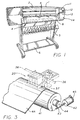
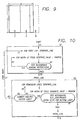
- the printer/plotter includes a main case 1 (Fig. 1) with a window 2, and a left-hand pod 3 that encloses one end of the chassis. Within that pod are carriage-support and -drive mechanics and one end of the printing-medium advance mechanism, as well as a pen-refill station with supplemental ink cartridges.
- the printer/plotter also includes a printing-medium roll cover 4, and a receiving bin 5 for lengths or sheets of printing medium on which images have been formed, and which have been ejected from the machine.
- a bottom brace and storage shelf 6 spans the legs which support the two ends of the case 1.
- an entry slot 7 for receipt of continuous lengths of printing medium 4. Also included are a lever 8 for control of the gripping of the print medium by the machine.
- a front-panel display 11 and controls 12 are mounted in the skin of the right-hand pod 13. That pod encloses the right end of the carriage mechanics and of the medium advance mechanism, and also a printhead cleaning station. Near the bottom of the right-hand pod for readiest access is a standby switch 14.
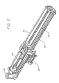
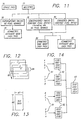
- the carriage assembly 20 (Fig. 2) is driven in reciprocation by a motor 31 - along dual support and guide rails 32, 34 - through the intermediary of a drive belt 35.
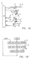
- the motor 31 is under the control of signals 31A from a digital electronic microprocessor 17 (Fig. 1A).
- the carriage assembly is represented separately at 20 when traveling to the left 16 while discharging ink 18, and at 20' when traveling to the right 17 while discharging ink 19.
- a very finely graduated encoder strip 33 is extended taut along the scanning path of the carriage assembly 20, 20', and read by an automatic optoelectronic sensor 37 to provide position and speed information 37B for the microprocessor 15.
- the codestrip 33 thus enables formation of color inkdrops at ultrahigh precision (as mentioned earlier, typically 24 pixels/mm) during scanning of the carriage assembly 20 in each direction - i. e. , either left to right (forward 20') or right to left (back 20)
- a currently preferred location for the encoder strip 33 is near the rear of the carriage tray (remote from the space into which a user's hands are inserted for servicing of the pen refill cartridges).
- Immediately behind the pens is another advantageous position for the strip 36 (Fig. 3).
- the sensor 37 is disposed with its optical beam passing through orifices or transparent portions of a scale formed in the strip.
- Print medium 4A is thereby drawn out of the print-medium roll cover 4, passed under the pens on the carriage assembly 20, 20' to receive inkdrops 18, 19 for formation of a desired image, and ejected into the print-medium bin 5.
- the carriage assembly 20, 20' includes a previously mentioned rear tray 21 (Fig. 4) carrying various electronics. It also includes bays 22 for preferably four pens 23-26 holding ink of four different colors respectively - preferably yellow in the leftmost pen 23, then cyan 24, magenta 25 and black 26.
- Each of these pens particularly in a large-format printer/plotter as shown, preferably includes a respective ink-refill valve 27.
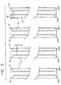
- the pens unlike those in earlier mixed-resolution printer systems, all are relatively long and all have nozzle spacing 29 (Fig. 5) equal to one-twelfth millimeter - along each of two parallel columns of nozzles. These two columns contain respectively the odd-numbered nozzles 1 to 299, and even-numbered nozzles 2 to 300.
- the two columns thus having a total of one hundred fifty nozzles each, are offset vertically by half the nozzle spacing, so that the effective pitch of each two-column nozzle array is approximately one-twenty-fourth millimeter.
- the natural resolution of the nozzle array in each pen is thereby made approximately twenty-four nozzles (yielding twenty-four pixels) per millimeter.
- the system For resupply of ink to each pen the system includes a refill cartridge 51 (Fig. 6), with a valve 52, umbilicus 53 and connector nipple 54. The latter mates with supply tubing within the printer/plotter refill station (in the left-hand pod 3).
- Each supply tube in turn can complete the connection to the previously mentioned refill valve 27 on a corresponding one of the pens, when the carriage is halted at the refill station.
- a user manually inserts (Fig. 7) each refill cartridge 51 into the refill station as needed.
- all print modes are bidirectional. In other words, consecutive passes are printed 19, 18 while traveling in both directions, alternating left-to-right scans 17 with right-to-left 16.
- black (or other monochrome) and color are treated identically as to speed and most other parameters.
- the number of printhead nozzles used is always two hundred forty, out of the three hundred nozzles (Fig. 5) in the pens.
- the system of the preferred embodiment has three printing speed/quality settings, which determine resolution, number of passes to complete inking of each swath (or more precisely each subswath), and carriage velocities as approximately: best quality normal fast resolution (pixels/mm) 24 12 12 passes to complete swath 8 or 10 4 or 6 2 carriage velocity (cm/sec) 51 or 631 ⁇ 2 631 ⁇ 2 631 ⁇ 2.
- best quality normal fast resolution pixels/mm
- carriage velocity cm/sec
- the varying choices indicated here are for correspondingly various media - for example carriage velocity is 631 ⁇ 2 cm/sec, except that 51 cm/sec is used for best-quality printing on glossy stock.
- Resolution is the same in both horizontal and vertical directions, i. e. row and column spacings are the same so that pixels 57 (Fig. 8) are 24 mm square for all settings.
- Low-resolution printing instead calculates the inking only for every other position in the grid (along each of the perpendicular axes or dimensions) and implements that inking with one or more double-height, double-width compound inkdrop structures 58 - each made up of a two-by-two assemblage of individual inkdrops. Since calculations are done for only half the rows and half the columns, the number of points calculated is just one quarter of all the points in the grid.
- Such developments will lead to continuingly improved print quality.
- Such quality improvements may in particular materialize in, for example, even images printed using the fast-mode settings.
- the medium advances 42A (Fig. 1B) after each full reciprocation 19, 18 of the pen carriage, and the distance of that advance is most commonly a fraction of the height of each used nozzle array ( i. e. , swath).
- the operation is as for superimposed swaths; as to successive passes between which the medium is advanced, the operation is as for staggered swaths.
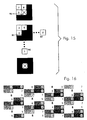
- An example of multipass staggered-swath masking employed in preferred embodiments of the present invention may be represented in any of at least three equivalent notations 91, 92, 93 (Fig. 14).
- the most graphically plain notation 92 is essentially a representation of a part of the pixel grid, as addressed in each of four passes.
- each pass is represented by a separate rectangle containing numerals (ones and zeroes) in rows and columns.
- Each row in each rectangle is part of a row in a particular portion of the overall pixel grid of the image, and each column in each rectangle is part of a column in the same portion of the overall pixel grid.
- these rectangles are repeatedly stepped, so that the pattern is reused many times; however, in most preferred high-quality printmodes the mask is much larger than the example, so that considerably less repetition is present.
- a "1" means that that particular pixel is addressed - i. e. , printed if there is anything to print - during the pass represented by the rectangle under consideration.
- the system addresses the pixel second from the left in the top row, the pixel at the far right in the second row, and that at the far left in the third row. It also addresses the pixel third from the left in the bottom row.
- the numerals "3142" across the top row of the rectangle 93 mean that the pixel positions in which these numerals appear are addressed in, respectively, passes number three, one, four and two.
- This system can be related to the central rectangles 92 by noting which of those rectangles 92 has a "1" in the same respective pixel positions: the third rectangle for the top-left pixel, first rectangle for the second pixel, etc.
- a two-pass/one-advance mode such as shown in Fig. 21 requires a full-height advance. In such a case successive swath pairs are abutted, leading to some banding; however, Fig. 21 does represent an optimal fast mode for certain media.
- one ideal objective is row and column randomization, to minimize patterning while maintaining throughput.
- another important ideal objective is wide separation between inkdrops laid down in the same pass - and also in temporally nearby passes - to minimize puddling while maintaining throughput.
- the first of these rules derives from well-known coalescence or puddling considerations, i. e. from concerns about overinking. It focuses upon immediately adjacent horizontal neighbor 4 (Fig. 15) - where the center pixel 95 in the diagram represents a pixel currently under consideration - and also immediately adjacent vertical neighbor 5, and immediately adjacent diagonal neighbor 3.
- the second rule actually arises from firing-frequency limitations, as mentioned earlier, but also of course helps to minimize overinking by spreading printed dots as much as possible. It focuses on "firing-frequency neighbors" 2.
- the maximum firing frequency is 7.5 kHz, and a design objective is to stay at least a factor of two below that value.
- the effective frequency is four to eight times lower than that value, for a very fully effective margin of error.
- the third rule is directed to overinking, and focuses on "vertical frequency" neighbors 1.
- the fourth rule is concerned with the same, but in regard to possibly-incompletely-dried inkdrops deposited in the immediately preceding pass - i. e. , what may be called a "horizontal-temporal” neighbor 6, "vertical-temporal” neighbor 8, and "diagonal-temporal” neighbor 7.
- the fifth and final rule is essentially the same as the first but focused upon the regions where adjoining masks come together.
- positions 1 and 2 are influenced primarily by pen parameters (firing capabilities), while the other positions are critical for ink and media artifacts.
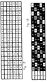
- Figs. 16 through 21 display the masks chosen from those randomly generated, after testing as described above. As mentioned earlier, some of the smaller masks were generated manually but still with attention to selection of the numbers at random.
- the mask of Fig. 16 was found to produce best printed image quality for glossy stock, and also for a vinyl printing medium, and accordingly was selected for use at the "best" mode setting for those two media. It is familiarly called a “knight” printmask because the pixels assigned to each pass appear, relative to one another, two pixels over and one down - like the move of the piece called a "knight” in the game of chess.
- the Fig. 17 mask when tested produced best image quality on matte stock, and Fig. 18 best image quality when backlit - in other words, used for overhead projection or simply in a backlit display frame as in some types of advertising displays. It is a "two hundred percent of ink" mode, in which all normal inking is doubled.
- the mask of Fig. 17 is used at the "best" print-quality setting on matte, and Fig. 18 for backlit transparencies.
- the Fig. 19 mask is used in the "normal" setting for glossy, heavy matte and vinyl. Inspection of the information shows clearly that several of the location rules are relaxed.
- Fig. 20 shows a mask used for "normal” printing on backlit transparency media (at two hundred percent inking), and also for “fast” printing on glossy and vinyl stock - all at four passes and four advances.
- Fig. 21 is used for "normal” printing on matte, with four passes and two advances; and
- Fig. 22 is used at the "fast” setting on a matte medium, with two passes and one advance.
- each printhead is made with - pursuant to convention - two rows of nozzles, the two rows being offset by half the nozzle spacing in each row. If a printmode happens to call for addressing, say, all odd -numbered nozzles in one pass and all even in the next pass, this seemingly arbitrary specification has a physical significance which may be unintended: in heavily inked regions, what will fire is in the first pass the entire left-hand column of nozzles and then, in the second, the entire right-hand column.
- pens are generally made with one common ink-supply channel supplying all the ink chambers in the left-hand row, and another distinct common channel supplying all the chambers in the right-hand row. Firing all odd or all even nozzles therefore selectively drains only one or the other supply channel, tending through liquid-flow impedance effects to aggravate any tendency of some nozzles to fire weakly.
- These may be, for example, the nozzles furthest from the channel source inlets - or those which happen to have been made with aperture sizes low-within-tolerance.
- the mask of Fig. 22 calls for firing in a single pass (pass "1", for example) two vertically adjacent pixels in the upper right corner of the mask - which means two nozzles in immediate succession in the numbering sequence. These are, physically, one adjacent nozzle in each of the two columns. Thereby liquid loading is distributed equally between the two supply channels, not concentrated in one or the other. The same sharing of the hydraulic loading is seen whichever pass is considered.
- the masks are simply called up automatically. They are selected by the combination of print-quality and print-medium settings which a user of the printer/plotter enters at the control panel 12, as verified by the display 11.
- Each pass number in a particular cell of a mask is applied directly by the system central processor, to cause the carriage drive 31, medium-advance drive 42-44, encoder sensor 37, and pen nozzles (Fig. 5) with associated firing devices all to cooperate in implementing the pass-number indication. That is, they cooperate in such a way that all the pixels corresponding to that particular cell will be printed during the indicated pass - if there is anything to print in those pixels respectively.
Landscapes
- Engineering & Computer Science (AREA)
- Physics & Mathematics (AREA)
- Mathematical Physics (AREA)
- General Engineering & Computer Science (AREA)
- General Physics & Mathematics (AREA)
- Theoretical Computer Science (AREA)
- Quality & Reliability (AREA)
- Ink Jet (AREA)
- Particle Formation And Scattering Control In Inkjet Printers (AREA)
Claims (11)
- Vorrichtung zum Drucken eines Farbbilds auf einem Druckmedium (4A); wobei die Vorrichtung folgende Merkmale aufweist:wobei die Druckkopfeinrichtung einen Düsenabstand (28) aufweist, der gleich der Pixelzeilenbeabstandung ist;eine bewegliche Tintenstrahldruckkopfeinrichtung (20, 20', 31, 42) zum Erzeugen eines Farbbilds als Tintentropfen (18, 19) in einem Pixelgitter von mehreren Zeilen und Spalten auf einem derartigen Medium, wobei die Zeilen durch eine Zeilenbeabstandung (28) beabstandet sind;
eine Einrichtung zum Erstellen einer Druckmaske, wobei Positionsregeln (63, 67) im Wesentlichen innerhalb jeder Abtastung ein Adressieren irgendwelcher unmittelbar benachbarter Pixel (3 - 5) in irgendeiner horizontalen, vertikalen oder diagonalen Richtung verhindern; und
eine Einrichtung (15) zum Anwenden der Druckmaske, um die Tintenstrahldruckkopfeinrichtung zu steuern (20B, 31A, 42A). - Die Vorrichtung gemäß Anspruch 1, bei der:eine volle Einfärbung jeder Region des Druckmediums fünf Durchläufe erfordert; unddie Druckmaske den Durchlauf, bei dem jedes Pixel adressiert wird, durch dieses Sechzehn-mal-Fünf-Muster von Durchlaufzahlen identifiziert:
4 1 4 2 3 5 3 5 2 1 4 2 3 5 3 5 3 5 2 1 4 1 4 2 3 5 2 1 4 1 2 2 4 2 3 5 3 5 2 1 4 1 3 5 3 5 2 1 2 1 4 1 4 2 3 5 3 5 4 1 4 2 3 5 3 5 3 5 2 1 4 1 4 2 3 5 2 1 4 3. - Die Vorrichtung gemäß Anspruch 1, bei der:ein volles Einfärben jeder Region des Druckmediums sechs Durchläufe erfordert; unddie Druckmaske den Durchlauf, bei dem jedes Pixel adressiert wird, durch dieses Sechzehn-mal-Zehn-Muster von Durchlaufzahlen identifiziert:
1 5 3 4 2 6 1 5 3 4 2 6 1 5 4 6 4 2 6 1 5 3 4 2 6 1 5 3 4 2 1 3 1 5 3 4 2 6 1 5 3 4 2 6 1 5 4 6 4 2 6 1 5 3 4 2 6 1 5 3 4 2 1 3 5 3 4 2 6 1 5 3 4 2 6 1 5 4 6 1 2 6 1 5 3 4 2 6 1 5 3 4 2 1 3 4 5 3 4 2 6 1 5 3 4 2 6 1 5 4 6 1 2 6 1 5 3 4 2 6 1 5 3 4 2 1 3 4 3 4 2 6 1 5 3 4 2 6 1 5 4 6 1 5 6 1 5 3 4 2 6 1 5 3 4 2 1 3 4 2. - Die Vorrichtung gemäß Anspruch 1, bei der die Druckmaskenerstelleinrichtung ferner eine Einrichtung zum Erstellen der Druckmaske aufweist, so dass:die Druckmaske eine Höhe (88) aufweist; undPositionsregeln ferner im Wesentlichen bei jeder Abtastung (16, 17) ein Adressieren irgendwelcher vertikal benachbarter Pixel (96) innerhalb der gesamten Höhe der Druckmaske verhindern.
- Die Vorrichtung gemäß Anspruch 4, bei der:es zehn Durchläufe gibt; unddie Druckmaske den Durchlauf, bei dem jedes Pixel adressiert wird, durch dieses Sechzehn-mal-Fünf-Muster von Durchlaufzahlen identifiziert:
7 1 6 2 5 8 4 9 3 10 6 2 5 8 4 9 4 9 3 10 7 1 6 2 5 8 3 10 7 1 6 2 6 2 5 8 4 9 3 10 7 1 5 8 4 9 3 10 3 10 7 1 6 2 5 8 4 9 7 1 6 2 5 8 5 8 4 9 3 10 7 1 6 2 4 9 3 10 7 1. - Die Vorrichtung gemäß Anspruch 4, bei der die Druckmaskenerstelleinrichtung ferner eine Einrichtung zum Erstellen der Druckmaske aufweist, so dass:die Druckmaske ferner eine Breite (87) aufweist; undPositionsregeln ferner bei jeder Abtastung (16, 17) im Wesentlichen ein Adressieren irgendwelcher horizontal benachbarter Pixel (97) innerhalb der gesamten Breite der Druckmaske verhindern.
- Die Vorrichtung gemäß Anspruch 6, bei der:die Druckmaske ein Acht-mal-Acht-"Springer"-Muster ist.
- Die Vorrichtung gemäß Anspruch 6, bei der:es vier Durchläufe gibt; unddie Druckmaske den Durchlauf, bei dem jedes Pixel adressiert wird, durch dieses Vier-mal-Vier-Muster von Durchlaufzahlen identifiziert:
4 1 3 2 3 2 4 1 1 4 2 3 2 3 1 4. - Die Vorrichtung gemäß Anspruch 1, bei der:die Druckmaske insbesondere ein Adressieren irgendwelcher unmittelbar benachbarter Pixel (3 - 5) in irgendeine Richtung entlang Grenzen zwischen vertikal angrenzenden Bändern (67) oder horizontal angrenzenden Masken (F) oder beidem verhindert.
- Ein Verfahren zum Erzeugen und Verwenden einer Druckmaske für eine verbesserte Druckqualität bei einem Tintenstrahldrucker; wobei das Verfahren folgende Schritte aufweist:automatisches Erzeugen einer Reihe von Zahlen für eine Verwendung bei einem Definieren von Zeilen oder Spalten, oder beidem, eines Pixelgitters zum Drucken in aufeinanderfolgenden Durchläufen (18, 19) eines Druckkopfs (20, 20', 23 - 26);automatisches Testen (63, 67) jeder Zahl bezüglich Positionsregeln für eine Minimierung einer Tintenkoaleszenz und einer Pfützenbildung;automatisches Sammeln (65, 72) der Zahlen als ein strukturiertes Array zum Definieren von Zeilen und Spalten eines Pixelgitters zum Drucken in aufeinanderfolgenden Durchläufen (16, 17) eines Druckkopfs;wirksames Überprüfen einer Leistungsfähigkeit des Arrays und anderer, die ähnlich erzeugt sind, für eine Auswahl zumindest eines bevorzugten Arrays; undSpeichern des Arrays für einen späteren automatischen Abruf und eine Verwendung bei einem Steuern (20B, 31A, 32A) eines Druckers.
- Das Verfahren gemäß Anspruch 10, das ferner folgenden Schritt aufweist:Abrufen und Verwenden des gespeicherten Musters zum Steuern (20B, 31A, 32A) eines Druckers.
Applications Claiming Priority (2)
| Application Number | Priority Date | Filing Date | Title |
|---|---|---|---|
| US810753 | 1997-03-04 | ||
| US08/810,753 US6067405A (en) | 1997-03-04 | 1997-03-04 | Multipass color printmasks based on location rules to minimize hue shift, banding and coalescence |
Publications (3)
| Publication Number | Publication Date |
|---|---|
| EP0863480A2 EP0863480A2 (de) | 1998-09-09 |
| EP0863480A3 EP0863480A3 (de) | 2000-08-30 |
| EP0863480B1 true EP0863480B1 (de) | 2005-12-21 |
Family
ID=25204619
Family Applications (1)
| Application Number | Title | Priority Date | Filing Date |
|---|---|---|---|
| EP98301573A Expired - Lifetime EP0863480B1 (de) | 1997-03-04 | 1998-03-03 | Verfahren und Vorrichtung für Farbtintenstrahldruck mit Mehrfach-Durchlauf |
Country Status (4)
| Country | Link |
|---|---|
| US (1) | US6067405A (de) |
| EP (1) | EP0863480B1 (de) |
| JP (1) | JPH10244674A (de) |
| DE (1) | DE69832834T2 (de) |
Families Citing this family (30)
| Publication number | Priority date | Publication date | Assignee | Title |
|---|---|---|---|---|
| JP3679553B2 (ja) * | 1997-06-26 | 2005-08-03 | キヤノン株式会社 | インクジェット記録装置及びインクジェット記録方法 |
| JPH11216856A (ja) * | 1997-11-14 | 1999-08-10 | Canon Inc | 記録装置および方法 |
| JP3762117B2 (ja) * | 1998-09-30 | 2006-04-05 | キヤノン株式会社 | 記録装置および記録方法 |
| EP1029688A1 (de) * | 1999-02-17 | 2000-08-23 | Hewlett-Packard Company | Druckgerät und Verfahren zum Drucken |
| US6545773B1 (en) * | 1999-03-01 | 2003-04-08 | Hewlett-Packard Company | Compensation for print-direction induced hue shift using depletion |
| US6856428B1 (en) | 1999-06-10 | 2005-02-15 | Electronics For Imaging, Inc. | Black text printing from page description languages |
| US6254217B1 (en) * | 1999-07-29 | 2001-07-03 | Hewlett-Packard Company | Apparatus and method for hue shift compensation in a bidirectional printer |
| JP4095210B2 (ja) * | 1999-08-24 | 2008-06-04 | キヤノン株式会社 | 記録方法および記録装置 |
| US6443556B1 (en) * | 2000-02-29 | 2002-09-03 | Hewlett-Packard Company | Automated and semiautomated printmask generation for incremental printing |
| US6623894B2 (en) | 2001-03-14 | 2003-09-23 | Kodak Polychrome Graphics, Llc | Laser-induced thermal imaging with masking |
| NL1018114C2 (nl) * | 2001-05-21 | 2002-11-25 | Oce Tech Bv | Inkjetprinter en een werkwijze voor het bedrukken van een ontvangstmateriaal. |
| US6597388B2 (en) | 2001-06-21 | 2003-07-22 | Kodak Polychrome Graphics, Llc | Laser-induced thermal imaging with masking |
| US7016082B2 (en) * | 2001-07-05 | 2006-03-21 | Kodak Polychrome Graphics, Llc | Halftone dot thinning |
| US6888558B2 (en) * | 2001-12-19 | 2005-05-03 | Kodak Polychrome Graphics, Llc | Laser-induced thermal imaging with masking |
| US7116821B2 (en) * | 2002-03-25 | 2006-10-03 | Lexmark International, Inc. | Color trapping for an image forming apparatus |
| EP1512177A2 (de) * | 2002-05-27 | 2005-03-09 | Koninklijke Philips Electronics N.V. | Verfahren zur beschichtung einer substratoberfläche mit einer gemusterten schicht |
| JP4206706B2 (ja) * | 2002-08-23 | 2009-01-14 | セイコーエプソン株式会社 | プラテンを汚すことなく印刷用紙の端部まで行う印刷 |
| JP2004255700A (ja) * | 2003-02-26 | 2004-09-16 | Seiko Epson Corp | メモリ容量の節約を考慮したドットデータ作成処理 |
| US6817697B2 (en) * | 2003-04-14 | 2004-11-16 | Lexmark International, Inc. | Systems and methods for printhead architecture hardware formatting |
| US20050135677A1 (en) * | 2003-12-22 | 2005-06-23 | Seevers Timothy S. | Method and apparatus for acquiring image data from a scanned document |
| KR100548131B1 (ko) * | 2004-01-28 | 2006-02-02 | 삼성전자주식회사 | 화상형성기기의 인쇄방법 |
| US6866365B1 (en) | 2004-04-01 | 2005-03-15 | Eastman Kodak Company | Bi-directional color printer and method of printing |
| US7118191B2 (en) * | 2004-06-28 | 2006-10-10 | Lexmark International, Inc. | Apparatus and method for ink jet printing using variable interlacing |
| US7452046B2 (en) * | 2004-10-27 | 2008-11-18 | Hewlett-Packard Development Company, L.P. | Method for preparing a print mask |
| US20060087527A1 (en) * | 2004-10-27 | 2006-04-27 | De Pena Alejandro M | Method for preparing a print mask |
| JP2008100497A (ja) * | 2006-09-19 | 2008-05-01 | Ricoh Co Ltd | 印写方法、画像形成装置、制御プログラム、当該プログラムを搭載した情報記録媒体、これらを具備する画像形成システム、印写用記録媒体、印写した記録物、及びインク |
| US20090033694A1 (en) * | 2007-07-31 | 2009-02-05 | Yang Shi | Printer control system and method for artifact free and borderless printing |
| US8235489B2 (en) * | 2008-05-22 | 2012-08-07 | Fujifilm Dimatix, Inc. | Ink jetting |
| US8123319B2 (en) * | 2009-07-09 | 2012-02-28 | Fujifilm Corporation | High speed high resolution fluid ejection |
| JP5899564B2 (ja) * | 2010-12-30 | 2016-04-06 | シクパ ホルディング ソシエテ アノニムSicpa Holding Sa | インクジェット印刷方法 |
Family Cites Families (13)
| Publication number | Priority date | Publication date | Assignee | Title |
|---|---|---|---|---|
| US4748453A (en) | 1987-07-21 | 1988-05-31 | Xerox Corporation | Spot deposition for liquid ink printing |
| US4963882B1 (en) * | 1988-12-27 | 1996-10-29 | Hewlett Packard Co | Printing of pixel locations by an ink jet printer using multiple nozzles for each pixel or pixel row |
| US4943816A (en) * | 1989-06-14 | 1990-07-24 | International Business Machines Corporation | High quality thermal jet printer configuration suitable for producing color images |
| US4965593A (en) * | 1989-07-27 | 1990-10-23 | Hewlett-Packard Company | Print quality of dot printers |
| EP0817113B1 (de) * | 1991-08-02 | 2003-09-24 | Canon Kabushiki Kaisha | Tintenstrahlaufzeichnungsverfahren |
| US5502792A (en) * | 1992-08-03 | 1996-03-26 | Hewlett-Packard Company | Method for reducing pixel density along one axis of a multiple dimension image representation |
| US5555006A (en) * | 1993-04-30 | 1996-09-10 | Hewlett-Packard Company | Inkjet printing: mask-rotation-only at page extremes; multipass modes for quality and throughput on plastic media |
| US5677716A (en) * | 1993-04-30 | 1997-10-14 | Hewlett-Packard Company | Maximum-diagonal print mask and multipass printing modes, for high quality and high throughput with liquid-base inks |
| EP0622230A3 (de) * | 1993-04-30 | 1995-07-05 | Hewlett Packard Co | Verfahren zum bidirektionalen Drucken. |
| US5818474A (en) * | 1993-06-30 | 1998-10-06 | Canon Kabushiki Kaisha | Ink-jet recording apparatus and method using asynchronous masks |
| US5485183A (en) * | 1993-06-30 | 1996-01-16 | Dataproducts Corporation | Interlaced dot-on-dot printing |
| IT1273141B (it) * | 1994-04-14 | 1997-07-04 | Olivetti Canon Ind Spa | Metodo per migliorare la stampa di immagini grafiche e relativa apparecchiatura di stampa a matrice di punti a getto di inchiostro |
| JPH08300642A (ja) * | 1995-04-03 | 1996-11-19 | Xerox Corp | 液体インクプリンタによるランダム印刷法 |
-
1997
- 1997-03-04 US US08/810,753 patent/US6067405A/en not_active Expired - Lifetime
-
1998
- 1998-02-25 JP JP10059086A patent/JPH10244674A/ja active Pending
- 1998-03-03 EP EP98301573A patent/EP0863480B1/de not_active Expired - Lifetime
- 1998-03-03 DE DE69832834T patent/DE69832834T2/de not_active Expired - Lifetime
Also Published As
| Publication number | Publication date |
|---|---|
| DE69832834T2 (de) | 2006-08-17 |
| DE69832834D1 (de) | 2006-01-26 |
| US6067405A (en) | 2000-05-23 |
| EP0863480A2 (de) | 1998-09-09 |
| EP0863480A3 (de) | 2000-08-30 |
| JPH10244674A (ja) | 1998-09-14 |
Similar Documents
| Publication | Publication Date | Title |
|---|---|---|
| US6367908B1 (en) | High-resolution inkjet printing using color drop placement on every pixel row during a single pass | |
| EP0863480B1 (de) | Verfahren und Vorrichtung für Farbtintenstrahldruck mit Mehrfach-Durchlauf | |
| EP0863478B1 (de) | Verfahren und Vorrichtung für Tintenstrahldruck mit Mehrfach-Durchlauf | |
| US6250739B1 (en) | Bidirectional color printmodes with semistaggered swaths to minimize hue shift and other artifacts | |
| US5600353A (en) | Method of transitioning between ink jet printing modes | |
| EP0622212B1 (de) | Bild-Druckverfahren | |
| EP0622211B1 (de) | Tintenstrahldruckverfahren auf Kunststoffaufzeichnungsmaterial | |
| EP0730968B1 (de) | Maskendruck, abhängig von Auflösung und Farbe | |
| US5949453A (en) | Mixed resolution printing for color and monochrome printers | |
| US6142605A (en) | Bidirectional color printing using multipass printmodes with at least partially swath-aligned inkjet printheads | |
| US6082849A (en) | Random printmasks in a multilevel inkjet printer | |
| US6086181A (en) | Maximum-diagonal print mask and multipass printing modes, for high quality and high throughput with liquid-base inks | |
| US6582056B2 (en) | Edge enhancement depletion technique for over-sized ink drops to achieve high resolution X/Y axes addressability in injet printing | |
| US6017113A (en) | Mixed-density print masking in a mixed-swath-height printer | |
| US6217150B1 (en) | Method of printing with an ink jet printer using multiple carriage speeds | |
| US5959646A (en) | Method of printing with an ink jet printer using independent shingling on a raster by raster basis | |
| KR19980032994A (ko) | 스오스 프린팅 시스템 및 칼라 드롭의 분배를 제어하는 방법 | |
| EP0730367A1 (de) | Verfahren und System für verflochtenen Druck | |
| US5779377A (en) | Printing apparatus | |
| JPH10157171A (ja) | インクジェットプリントにおける高解像度のx/y軸アドレス指定能力のためのプロットに依存しない領域充填削減技法 | |
| US6629752B1 (en) | Method of ink jet printing with enhanced shingling and printer apparatuses for the same | |
| EP0730248A1 (de) | Verfahren und System für verflochtenen Druck | |
| EP1216154B1 (de) | Tintenstrahldruckverfahren mit verbesserter überlappung und zugehöriges druckgerät | |
| JPH10157095A (ja) | カラーインクジェットプリントにおける高解像度のアドレス指定能力のための外部寸法の完全性 |
Legal Events
| Date | Code | Title | Description |
|---|---|---|---|
| PUAI | Public reference made under article 153(3) epc to a published international application that has entered the european phase |
Free format text: ORIGINAL CODE: 0009012 |
|
| AK | Designated contracting states |
Kind code of ref document: A2 Designated state(s): DE ES FR GB |
|
| AX | Request for extension of the european patent |
Free format text: AL;LT;LV;MK;RO;SI |
|
| PUAL | Search report despatched |
Free format text: ORIGINAL CODE: 0009013 |
|
| AK | Designated contracting states |
Kind code of ref document: A3 Designated state(s): AT BE CH DE DK ES FI FR GB GR IE IT LI LU MC NL PT SE |
|
| AX | Request for extension of the european patent |
Free format text: AL;LT;LV;MK;RO;SI |
|
| RAP1 | Party data changed (applicant data changed or rights of an application transferred) |
Owner name: HEWLETT-PACKARD COMPANY, A DELAWARE CORPORATION |
|
| 17P | Request for examination filed |
Effective date: 20010202 |
|
| AKX | Designation fees paid |
Free format text: DE ES FR GB |
|
| 17Q | First examination report despatched |
Effective date: 20030709 |
|
| GRAP | Despatch of communication of intention to grant a patent |
Free format text: ORIGINAL CODE: EPIDOSNIGR1 |
|
| GRAS | Grant fee paid |
Free format text: ORIGINAL CODE: EPIDOSNIGR3 |
|
| GRAA | (expected) grant |
Free format text: ORIGINAL CODE: 0009210 |
|
| AK | Designated contracting states |
Kind code of ref document: B1 Designated state(s): DE ES FR GB |
|
| REG | Reference to a national code |
Ref country code: GB Ref legal event code: FG4D |
|
| REF | Corresponds to: |
Ref document number: 69832834 Country of ref document: DE Date of ref document: 20060126 Kind code of ref document: P |
|
| PG25 | Lapsed in a contracting state [announced via postgrant information from national office to epo] |
Ref country code: ES Free format text: LAPSE BECAUSE OF FAILURE TO SUBMIT A TRANSLATION OF THE DESCRIPTION OR TO PAY THE FEE WITHIN THE PRESCRIBED TIME-LIMIT Effective date: 20060401 |
|
| ET | Fr: translation filed | ||
| PLBE | No opposition filed within time limit |
Free format text: ORIGINAL CODE: 0009261 |
|
| STAA | Information on the status of an ep patent application or granted ep patent |
Free format text: STATUS: NO OPPOSITION FILED WITHIN TIME LIMIT |
|
| 26N | No opposition filed |
Effective date: 20060922 |
|
| REG | Reference to a national code |
Ref country code: GB Ref legal event code: 732E Free format text: REGISTERED BETWEEN 20120329 AND 20120404 |
|
| PGFP | Annual fee paid to national office [announced via postgrant information from national office to epo] |
Ref country code: GB Payment date: 20130228 Year of fee payment: 16 Ref country code: DE Payment date: 20130221 Year of fee payment: 16 |
|
| PGFP | Annual fee paid to national office [announced via postgrant information from national office to epo] |
Ref country code: FR Payment date: 20130429 Year of fee payment: 16 |
|
| REG | Reference to a national code |
Ref country code: DE Ref legal event code: R119 Ref document number: 69832834 Country of ref document: DE |
|
| GBPC | Gb: european patent ceased through non-payment of renewal fee |
Effective date: 20140303 |
|
| REG | Reference to a national code |
Ref country code: FR Ref legal event code: ST Effective date: 20141128 |
|
| REG | Reference to a national code |
Ref country code: DE Ref legal event code: R119 Ref document number: 69832834 Country of ref document: DE Effective date: 20141001 |
|
| PG25 | Lapsed in a contracting state [announced via postgrant information from national office to epo] |
Ref country code: GB Free format text: LAPSE BECAUSE OF NON-PAYMENT OF DUE FEES Effective date: 20140303 Ref country code: DE Free format text: LAPSE BECAUSE OF NON-PAYMENT OF DUE FEES Effective date: 20141001 Ref country code: FR Free format text: LAPSE BECAUSE OF NON-PAYMENT OF DUE FEES Effective date: 20140331 |