EP0863335B1 - Metallische Flachdichtung - Google Patents
Metallische Flachdichtung Download PDFInfo
- Publication number
- EP0863335B1 EP0863335B1 EP98103817A EP98103817A EP0863335B1 EP 0863335 B1 EP0863335 B1 EP 0863335B1 EP 98103817 A EP98103817 A EP 98103817A EP 98103817 A EP98103817 A EP 98103817A EP 0863335 B1 EP0863335 B1 EP 0863335B1
- Authority
- EP
- European Patent Office
- Prior art keywords
- bead
- zones
- gasket
- seal
- layer
- Prior art date
- Legal status (The legal status is an assumption and is not a legal conclusion. Google has not performed a legal analysis and makes no representation as to the accuracy of the status listed.)
- Revoked
Links
- 239000010410 layer Substances 0.000 claims description 103
- 239000011324 bead Substances 0.000 claims description 102
- 239000000463 material Substances 0.000 claims description 54
- 238000007789 sealing Methods 0.000 claims description 44
- 239000002184 metal Substances 0.000 claims description 31
- 238000000034 method Methods 0.000 claims description 22
- 239000002356 single layer Substances 0.000 claims description 18
- 230000015572 biosynthetic process Effects 0.000 claims description 17
- 239000007779 soft material Substances 0.000 claims description 17
- 238000004519 manufacturing process Methods 0.000 claims description 6
- 238000010438 heat treatment Methods 0.000 claims description 3
- 229910000975 Carbon steel Inorganic materials 0.000 claims description 2
- 239000010962 carbon steel Substances 0.000 claims description 2
- 238000010894 electron beam technology Methods 0.000 claims description 2
- 239000007769 metal material Substances 0.000 claims description 2
- 238000005755 formation reaction Methods 0.000 claims 11
- 229910000831 Steel Inorganic materials 0.000 claims 3
- 239000010959 steel Substances 0.000 claims 3
- 235000019589 hardness Nutrition 0.000 claims 2
- CWYNVVGOOAEACU-UHFFFAOYSA-N Fe2+ Chemical compound [Fe+2] CWYNVVGOOAEACU-UHFFFAOYSA-N 0.000 claims 1
- 230000000694 effects Effects 0.000 description 15
- 239000010421 standard material Substances 0.000 description 15
- 230000008901 benefit Effects 0.000 description 9
- 238000005452 bending Methods 0.000 description 7
- 230000008569 process Effects 0.000 description 7
- 230000008859 change Effects 0.000 description 6
- 230000001965 increasing effect Effects 0.000 description 6
- 239000007858 starting material Substances 0.000 description 5
- 238000005336 cracking Methods 0.000 description 4
- 230000001419 dependent effect Effects 0.000 description 3
- 239000003566 sealing material Substances 0.000 description 3
- 238000007669 thermal treatment Methods 0.000 description 3
- 229910000963 austenitic stainless steel Inorganic materials 0.000 description 2
- 238000002485 combustion reaction Methods 0.000 description 2
- 238000010276 construction Methods 0.000 description 2
- 238000010606 normalization Methods 0.000 description 2
- 230000036316 preload Effects 0.000 description 2
- 229910001220 stainless steel Inorganic materials 0.000 description 2
- 230000006978 adaptation Effects 0.000 description 1
- 230000002411 adverse Effects 0.000 description 1
- 230000005540 biological transmission Effects 0.000 description 1
- 229910010293 ceramic material Inorganic materials 0.000 description 1
- 239000012141 concentrate Substances 0.000 description 1
- 238000011161 development Methods 0.000 description 1
- 230000018109 developmental process Effects 0.000 description 1
- 238000007688 edging Methods 0.000 description 1
- 230000005670 electromagnetic radiation Effects 0.000 description 1
- 230000001939 inductive effect Effects 0.000 description 1
- 238000009434 installation Methods 0.000 description 1
- 230000007774 longterm Effects 0.000 description 1
- 239000000843 powder Substances 0.000 description 1
- 230000002028 premature Effects 0.000 description 1
- 238000002360 preparation method Methods 0.000 description 1
- 239000002994 raw material Substances 0.000 description 1
- 238000007493 shaping process Methods 0.000 description 1
- 238000005482 strain hardening Methods 0.000 description 1
- 230000007704 transition Effects 0.000 description 1
- 238000013316 zoning Methods 0.000 description 1
Images



Classifications
-
- F—MECHANICAL ENGINEERING; LIGHTING; HEATING; WEAPONS; BLASTING
- F16—ENGINEERING ELEMENTS AND UNITS; GENERAL MEASURES FOR PRODUCING AND MAINTAINING EFFECTIVE FUNCTIONING OF MACHINES OR INSTALLATIONS; THERMAL INSULATION IN GENERAL
- F16J—PISTONS; CYLINDERS; SEALINGS
- F16J15/00—Sealings
- F16J15/02—Sealings between relatively-stationary surfaces
- F16J15/06—Sealings between relatively-stationary surfaces with solid packing compressed between sealing surfaces
- F16J15/08—Sealings between relatively-stationary surfaces with solid packing compressed between sealing surfaces with exclusively metal packing
- F16J15/0818—Flat gaskets
- F16J15/0825—Flat gaskets laminated
-
- F—MECHANICAL ENGINEERING; LIGHTING; HEATING; WEAPONS; BLASTING
- F16—ENGINEERING ELEMENTS AND UNITS; GENERAL MEASURES FOR PRODUCING AND MAINTAINING EFFECTIVE FUNCTIONING OF MACHINES OR INSTALLATIONS; THERMAL INSULATION IN GENERAL
- F16J—PISTONS; CYLINDERS; SEALINGS
- F16J15/00—Sealings
- F16J15/02—Sealings between relatively-stationary surfaces
- F16J15/06—Sealings between relatively-stationary surfaces with solid packing compressed between sealing surfaces
- F16J15/08—Sealings between relatively-stationary surfaces with solid packing compressed between sealing surfaces with exclusively metal packing
- F16J15/0818—Flat gaskets
- F16J2015/0837—Flat gaskets with an edge portion folded over a second plate or shim
-
- F—MECHANICAL ENGINEERING; LIGHTING; HEATING; WEAPONS; BLASTING
- F16—ENGINEERING ELEMENTS AND UNITS; GENERAL MEASURES FOR PRODUCING AND MAINTAINING EFFECTIVE FUNCTIONING OF MACHINES OR INSTALLATIONS; THERMAL INSULATION IN GENERAL
- F16J—PISTONS; CYLINDERS; SEALINGS
- F16J15/00—Sealings
- F16J15/02—Sealings between relatively-stationary surfaces
- F16J15/06—Sealings between relatively-stationary surfaces with solid packing compressed between sealing surfaces
- F16J15/08—Sealings between relatively-stationary surfaces with solid packing compressed between sealing surfaces with exclusively metal packing
- F16J15/0818—Flat gaskets
- F16J2015/0843—Flat gaskets with an edge portion folded over the plate itself
Definitions
- the invention relates to a metallic flat gasket, in particular a Cylinder head gasket, according to the preamble of claim 1.
- Such known seals often consist of several laminated Sheet metal plates, often around the cylinder opening Compensation area of the seal is provided, in which the sum of the Thickness of the various sheet metal plates is larger than in the rest of the part the seal and wherein at least one elastic outer sheet with a close the compensation area arranged bead is provided.
- DE 44 21 219 A1 is a one-piece metallic flat gasket known, on the opposite surfaces in the Recesses engaging material of the flat gasket.
- the Wells can, for example, be in the form of spherical sections or have straight, groove-shaped embossments.
- the wells can on the opposite surfaces of the flat gasket differ in shape and dimension. This allows Flat seals with selectively adjustable in individual areas produce different deformation and sealing properties; also the contact surfaces on both sides of the flat gasket can be different. This is an adjustment to a certain extent Counter surfaces made of different materials are possible between them should be sealed, and there may be different requirements for the individual areas of the sealing surface are taken into account.
- the US 4,964,293 A relates to a metallic cylinder head gasket, the is coated on both sides with a heat-resistant plastic and one Has bead or fold-like deformation. After installation, the Bead area the cylinder bore. Before using this Cylinder head gasket pressed between two metal plates and thus the Bead area of a targeted deformation and stress exposed to about 10 to 15 percent above operational stress lies. The temperature can also be increased by one Simulate approximation to the later operating conditions. in the metallurgical sense, this pre-stress is a Cold forming, which is a preload in the parts subjected to tension of the bead area. With the application of a preload Cold forming is said to make these cylinder head gaskets more uniform Dimensions and performance characteristics as well as an increased service life and maintain reliability. This type of work hardening is natural limited to the bead area.
- the Seal in immediate sealing area has beads or corrugations, the Seal consists of two layers of material. There is a layer of material arranged substantially flat, and the second material layer has in Sealing area the corrugations or corrugations on By providing the beading is the total clamping pressure acting on the seal concentrates a relatively small area, reducing the sealing effect of the Seal is increased.
- the metallic flat gasket has which especially the sealing of the cylinder head of internal combustion engines is used with at least one bead-like or fold-like deformation having layer of metal with a through hole, which a in essentially the diameter corresponding to the cylinder diameter has a bead-like deformation, which the through opening surrounds.
- the metallic flat gasket is used to seal flat components.
- the at least one layer of the seal topographically distributed zones with different, the mechanical Properties defining structure, which by Heat treatment can be achieved and discreet or overlapping each other can be arranged, the zones being arranged in position.
- a major advantage of the seal according to the invention is that the zones with different mechanical properties at the points the seal can be chosen differently, which is an optimal Allow sealing effect.
- the Sheet hardness can be influenced locally in a targeted manner.
- the mechanical Properties in the topographically distributed zones are thus purposefully not only through the structural treatment process, but also influenced by the starting material of the seal.
- a significant advantage of the seal according to the invention is that the Seal either in the bead area or essentially flat trained area of the seal or in both at defined points different desired mechanical properties can be provided can. This gives full constructive freedom regarding the topographic formation of the seal and its spring properties, Stiffness, hardness, permanent elasticity achievable. Under topographical In the broadest sense, the formation of the seal should not only be Surface shape, but also the local and / or cross-sectional different structure of the structure in the discretely distributed zones different mechanical properties can be understood. By a metallic flat gasket according to the invention it is thus possible Cylinder head gaskets e.g. B. also form single-layer for diesel engines.
- the zones are with different mechanical properties to the respective stiffness of the flat components.
- the zones preferably have different mechanical properties in places where the flat components have lower rigidity, greater strength than the rigidity of the flat components and in places where the flat ones Components have greater stiffness, less strength than that Rigidity of the flat components on the mechanical properties of the Zones of the seal can vary in terms of spring elasticity, Permanent elasticity, hardness, rigidity, strength, toughness, taking it understands that the mechanical properties mentioned with each other are dependent.
- the Invention the zones of different hardness.
- the seal is there preferably designed so that in the course of a bead, e.g. to the for through a cylinder provided through the hardness different places is different. In places where the components are softer, the bead is preferably made harder.
- Multi-cylinder arrangements are in the web area between the cylinders, in which several beads are arranged relatively close together, hardness and spring properties of the bead are preferably reduced so that the Sealing force effect in the circumference around the through opening Cylinder chamber is relatively balanced. This makes it possible to More even force application into the surrounding area of the seal components to be sealed.
- the seal is trained in one layer.
- a single-layer seal can suitable choice of the starting material an area of the bead or the entire bead with a greater hardness than on the essentially flat-shaped other areas of the seal. It is however also possible, depending on the mechanical properties of the seals Components, the seal in the substantially flat area also with topographically distributed zones of different mechanical Properties.
- a single-layer seal can also be used in optimally in terms of shape and local mechanical properties the sealing conditions are designed or set constructively.
- the seal is made from a laminate of layers of various sheet metal plates. At least one of the sheet metal plates has zones with different mechanical Properties on. However, it is also possible that several or all, the laminate forming sheet metal plates with such zones have different mechanical properties.
- the zones with Different mechanical properties can preferably be so be arranged so that the individual layers of the sheet metal plates each different places with such topographically distributed zones have different mechanical properties, so that for entire seal optimal mechanical properties to the desired Areas exist.
- the zones are with different mechanical properties preferably in the range of bead-like deformation provided. This allows the surround for the Sealing effect required high elasticity can be given without the required softness at the bridge points of the seal disadvantageous being affected.
- a metal sheet with softer Starting hardness before beading it is possible to have a crack-free beading realize, with a corresponding structural treatment the bead is adjustable to a desired final hardness or final strength.
- the zones have different mechanical Properties either in the surface area of the seal or in the entire cross-sectional area of the seal.
- the bead-like Deformation either designed as a single bead or as a double bead, Flanging or as a combination thereof.
- the type of surround Sealing depends on the one hand on the sealing force to be achieved and will on the other hand through the material and the negotiation process-dependent Structure influenced.
- the inner layers are preferably parallel areas of higher and lower strength of the outer layers bead-like deformation. This can, for example, force transmission and sealing effect can be positively influenced.
- the inner layers of the Bead-like deformation areas of higher and lower strength have, the strength of which is uniform or graded to the strengths of Outer layers merges.
- the different choice of zones or areas different mechanical properties for inner layers and outer layers a multi-layer seal serves to achieve optimal Sealing properties of the entire package seal.
- the Seal material from the group of carbon steel, ferritic Stainless steel, austenitic stainless steel, partially ferritic / austenitic stainless steel, Non-ferrous metal, sintered material, powder metal material or coated metal selected.
- the main advantage of the invention Seal exists among other things also in that through a targeted selection of materials a desired target hardness or target strength can be preselected. Because that Starting material delivers in Connection with a defined selected structural treatment Possibility to select the desired final hardness or target final strength certain zones of the seal.
- the Process according to the invention for producing a metallic Flat gasket the at least one metal layer from which the gasket exists, thermally treated in topographically distributed zones.
- the seal is pre-beaded by the thermal Treatment in the area of the beads a lower strength or hardness awarded, so that the beads are formed essentially without cracks is possible.
- This is mainly used when the Starting material has a relatively high hardness.
- the bead area is then formed into the seal thermally treated to a desired target final hardness or target final strength adjust so that the beading has the desired elasticity having.
- the preferred method for thermal treatment topographically distributed zones of the seal to achieve Structural changes are hardening.
- the individual zones are treated differently, so that the Seal in different places different mechanical Properties, in particular a different hardness.
- the different mechanical properties in the different zones are preferably selected so that an optimal coordination the surface hardness and / or the rigidity of the seal surrounding components to be sealed with the seal. This allows both Construction of the components to be sealed as well as their material and Material properties are met and the seal optimally on it can be set.
- the seal is at least double crimped or crimped, with a first inside Beading has a hardened zone, which by a corresponding softer material is surrounded, which has a second bead.
- This second bead is behind the first bead with respect to the through opening arranged and is so in the corresponding topographically distributed zones hardened that a desired spring elasticity is achieved.
- the topographically distributed zones are preferably mechanical Properties thermally treated with a laser.
- the zones with different mechanical properties with inductive working and / or based on microwaves, electron beams and / or Electromagnetic radiation working means thermally treated. ever according to heat influence or influenceability of the structural change of the different materials and depending on the thickness of each Material and depending on whether a treatment in Surface area or to be achieved in the entire cross-sectional area, the selection of the respective treatment method is made, so that the desired mechanical properties in the zones not only about the above material properties, but also through the choice of a suitable treatment process.
- Fig. 1 shows embodiments for single-layer seals according to the Invention, which in different areas, i.e. topographically distributed, Zones 1 to 3 with different mechanical properties.
- the number 1 always indicates a zone with the microstructure "soft", the number 2 a zone with the structure "hard” and the Number 3 a zone with the "Standard" structure.
- FIG. 1A is a schematic cross-sectional illustration of a single-layer seal with one arranged in the area of the passage opening of the seal Bead.
- the actual area of the bead-like deformation is soft executed (zone 1), which is characterized by hard or hardened areas (zone 2) Connect the seal.
- zone 1 which is characterized by hard or hardened areas (zone 2) Connect the seal.
- Such a seal can, for example, consist of a hard or hardened base material, which in the area of Beading has been normalized so that the beading is made of a soft material exists and can be easily shaped into the bead shape without the Risk of cracking due to deformation occurs.
- FIG. 1B is a cross-section of a single-layer seal according to FIG. 1A shown, in which, however, the area of the bead-like deformation as Zone 2, i.e. is hard or hardened, which is on both sides connect normalized or soft areas as Zone 1. Consequently such a seal has two topographically distributed zones 1, 2 different mechanical properties.
- a seal will preferably made of a normalized material, in one first process step, the bead is formed, which in a second Process step is treated-structure to the area of the bead-like To give deformation greater hardness (Zone 2).
- a bead with one Greater hardness has the advantage that it is necessary for the sealing function Elastic properties are more pronounced.
- FIG. 1C is a further embodiment of a single-layer seal shown in FIG. 1A.
- there is Seal made of a standard base material and thus Zone 3.
- Die Seal also has a bead-like deformation in the area of Through opening of the seal. Part of the bead-like deformation is as a normalized or soft area, i.e. trained as Zone 1.
- This upper area of curvature of the bead is subject to the Deformation process the highest bending forces and thus the highest Tendency to crack. Even microcracks that develop during the Form the deformation process and are initially not externally visible, can occur and the later long-term behavior of one in use adversely affect the existing seal. For this reason, this is Bead-like deformation area as a relatively soft area (Zone 1) educated. This is the elasticity of the bead-like deformation limited, but such seals are for moderate loads can be used successfully.
- FIG. 1D shows a further single-layer seal according to FIG. 1A, which also has an area in the flat part Standard material, i.e. as zone 3 and which has a normalized or soft bead (zone 1) including its edge areas. Since in this embodiment the entire area of the bead-like Deformation is soft, there is good moldability Beading without the risk of cracking. The elastic Properties of such a bead are limited.
- Fig. 1E shows another example of a single-layer seal, which a phase-shifted double bead in the area of the passage opening of the seal having.
- the basic body of the seal consists of a Standard material, i.e. as Zone 3, with only the most deformed Areas of the bead are normalized or soft, that is, as zone 2, analogous to Fig. 1C.
- Zone 3 a Standard material
- Zone 2 a Standard material
- the double bead makes the elastic Properties of the bead-like deformation in the area of Through opening increased while taking advantage of Crack-free deformation in the area of the greatest deformation of the bead remain guaranteed.
- Fig. 1F is a further single-layer seal with a double bead in Area of the passage opening of the seal is formed.
- the double bead is again arranged out of phase analogous to Fig. 1E, i.e. a bead opens downwards, while the neighboring bead opens upwards.
- the Bead-like deformations are essentially in cross section trapezoidal.
- 1G shows a further embodiment of a single-layer seal Zones with different mechanical properties are shown
- the bead has a semi-bead-like area in the area of the through opening Offset to which of a standard material in the sense of zone 3 gives existing seals a certain elasticity.
- zone 1 In the section of Seal between the bead and the through opening is an area normalized or soft material (zone 1), while in the Zone 2 between the bead and the outer edge of the seal greater hardness is arranged.
- the bead therefore has one in the sense of Influencing hardness Zones with different mechanical properties next to the bead.
- 1H is a single layer seal according to another Embodiment of the invention shown, which consists of a Standard material in the sense of zone 3 is that of the through opening facing end is flanged, whereby this area of the seal in Cross section is hook-like.
- the area of the "hook” of the Seal is formed from a hardened section as zone 2, so that a, based on the overall seal, partially hardened spring element in the immediate sealing area around the passage opening of the seal is trained around.
- the "hook” is expediently at untreated standard material (zone 3) and is shaped after Formation of the "hook” brought into the desired final hardness.
- Fig. 11 is also shown as a flanged half bead, the flanged area on the actual sealing body while leaving a space is folded back.
- One by the flanging emerging semicircular area, which during the flanging on most deformed and represents the critical bending zone is as hardened Zone 2 is formed to match the hook-like flanging To give spring stiffness.
- the one is hard Material section existing zone 2 after bending through Structural treatment of the corresponding material to the desired final hardness set.
- Fig. 1J shows the cross section of a seal of another Embodiment, the basic form of which is shown in Fig. 1I corresponds, in which, however, the critical bending zone as zone 1 a soft section of material is formed.
- a seal will especially used when there are no high elasticity requirements be placed on the bead area, but on the other hand when Bending over the hook-like flare absolutely prevents cracking shall be.
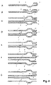
- 2A is a single layer seal according to another Embodiment of the invention shown.
- the seal is made of a standard material with Zone 3 and has a bead-like deformation and in the immediate vicinity of the Through opening of the seal arranged hook-like flanging.
- the bead-like deformation is trapezoidal and made of a hard or hardened material, i.e. designed as Zone 2.
- the critical bending zone (see Fig. 1J) also as a zone 1 with soft Properties trained.
- the treatment by which a hardening of the described areas of the seal is achieved after the shaping of the deformation areas.
- Such a seal has the advantage of high elasticity in the immediate sealing area.
- Zone 3 is a basically single-layer seal made of a standard material shown as Zone 3, which however is relatively far into the flat area of the seal guided folded back part. Through this far in The part folded back towards the flat part of the seal is in the actual sealing area, the seal is formed in two layers. Both superimposed areas, i.e. the folded back part of the Sealing material and the opposite part folded back Part of the sealing material essentially have one in phase Trapezoidal bead on the in the folded part in the Seal provided bead is as a zone 2 with hard material formed while the bead arranged underneath from a zone 1 with soft material is formed.
- the critical bending zone is analogous to that Fig. 1I also formed as a zone 2 hardened material.
- zone 1 made of soft material and zone 2 a combination of spring stiffness becomes lighter from hardened material Deformability and general strength in connection with numerous Sealing capacity adapted to the load conditions enables.
- zones of different mechanical properties 1 and 2 respectively Standard material of zone 3 of the seal is stamped after it has been shaped.
- a three-layer seal is formed in FIG. 2C.
- the top layer is out soft material made as Zone 1, while the middle layer from a Standard material is designed as zone 3 and in its form of single-layer 1I corresponds to the seal.
- the bottom layer is also out Standard material manufactured as Zone 3 and has one made of a hard or hardened material formed substantially trapezoidal bead, which mirror-symmetrical to a trapezoidal bead in the Upper layer is arranged.
- the immediate area which the The opening facing the seal is in the lower position also made of soft or normalized zone 1 material.
- FIG. 2D is a three-layer seal according to another Embodiment of the invention shown.
- the basic structure this three-layer bead corresponds to the structure according to FIG. 2C with the Difference that the middle layer in the area of symmetrical opposite beads of the top and bottom also a bead has, which is also substantially trapezoidal and is arranged in phases equal to the bead formed in the top layer.
- the flat area of the top layer and the hook-like flanging of the Middle layers are made of soft or normalized material in the sense Zone 1, while all other areas of the top layer, the Middle layer and the base made of hardened material, i.e. zone 2 consist.
- Such a seal is intended for use cases which in particular the elastic properties for a reliable and durable seal are important.
- Fig. 2E is also shown a three-layer seal, the principle Structure corresponds to that of Fig. 2C.
- the top layer and the base have the area of the bead facing away from the passage opening of the seal Transition area to the flat part of the seal on a hardened zone 2.
- the remaining part of the layers is made of soft or normalized material Zone 1 trained.
- the middle layer consists entirely of hardened or hard material of zone 2. Also preferred in this Embodiment the hardened areas after deforming and after the normalization at the described points of the seal.
- a four-layer seal which has an upper layer a trapezoidal bead with a zone 2 with hardened Area, a first middle layer in the shape of the middle layer according to FIG. 2E, at which, however, consists only of the region which is flanged in the form of a hook Zone 2 hardened material is formed, a second middle layer, which has a semi-corrugated step in the area of the through opening, the semi-corrugated gradation including the adjacent areas as zone consists of a hardened or hard material of zone 2, and the underlay with an oppositely opening trapezoidal bead in the Has area of the trapezoidal bead of the top layer, which as a zone 2 consists of hardened or hard material.
- 2G is a four-layer seal according to another Described embodiment of the invention, which in its basic Structure of the seal according to FIG. 2F corresponds, which however, in contrast have other zones 2 with harder material.
- the top layer has one Zone 2 hardened material covering the bead area as well as the area up to directly to the passage opening of the seal.
- the first The middle position corresponds in its design to the first middle position according to FIG. 2F.
- the geometric shape of the second middle layer is also identical to that according to FIG. 2F, this second central position covering the area of the half bead and the zone immediately adjacent to the passage opening 1 made of soft material and one essentially the flat stretched Has area 2 comprising hardened material.
- the bottom layer also corresponds to the lower layer according to FIG. 2F with the difference that the one directly next to the passage opening of the seal Area also belongs to zone 2 of the bead made of hardened material.
- FIG. 3A shows a further exemplary embodiment of a four-layer design Seal according to the invention.
- the Seal a soft top layer with a trapezoidal bead in the area of the passage opening of the seal.
- a first middle layer is designed to match the first top layer.
- the second middle layer corresponds to the second central position according to FIG. 2F.
- the document corresponds the document according to FIG. 2G.
- the three lower layers have one Zone 2 made of hard or hardened covering the entire area of the bead Material and a respective one encompassing the flat area of the seal Zone 1 made of normalized or soft material.
- Such a seal especially points in the immediate area of the bead, i.e. by doing Area in which the immediate sealing effect of the seal unfolds high spring stiffness.
- FIG. 3B shows a further exemplary embodiment of a four-layer design Seal according to the invention shown.
- the geometric shape of the individual layers basically corresponds to that according to FIG. 3A.
- the single ones Zones with different mechanical properties differ however, of those shown in FIG. 3A.
- the top layer is consistently of one soft material.
- the division of the zones of the first and the the second middle position correspond to those according to FIG. 3A.
- the zoning the base is reversed with respect to the zone division according to FIG. 3A, i.e. the area of the bead and the area of the through opening of the Seal are designed as zone 1 made of soft material, during the flat area of the lower layer as hardened area, i.e. as zone 2, is trained.
- Such a seal can be used, for example if the part located in the area of the beads of the individual layers of the components to be sealed has a relatively low strength.
- FIG. 3C shows a further exemplary embodiment of a four-layer design Seal according to the invention.
- the top layer is analogous to the top layer 3B formed.
- the two middle layers each point in essentially in the middle of the trapezoidal bead of the upper and Base on a semi-corrugated gradation, which is out of phase are arranged to each other so that the two middle layers are fork-shaped Form an arrangement.
- the first middle layer has a zone 1 made of soft Material on which the bead area and the directly to the Passage opening adjacent area, whereas you the flat area of the gasket encompassing a zone 2 of hard Represents material.
- the second middle layer points in the opposite direction arranged zones with different material properties, where the area surrounding the bead area and the area immediately adjacent to the Through hole as zone 2 made of hard material overlapping to zone 2 is formed from hard material of the first middle layer.
- the document is formed analogously to that shown in FIG. 3B.
- 3D shows a further embodiment of a seal according to the Invention represents.
- This seal has a first layer, which is a flat Section of soft material of zone 1 and a section with a Has double bead as zone 2 made of a hard material. The area of Double bead is completely as zone 2 made of hard or hardened Material trained.
- the second layer points in the area of the flat Section of the first layer has a trapezoidal bead as zone 2 made of hard or hardened material, which points towards one Double-beaded area of the first layer has a flat section also connects to zone 1 made of soft material, which has a circular deflection over the double bead Section of the first layer is folded as a leg
- the leg exists also made of soft material of zone 1, so that in the area of Double bead of the first layer creates a three-layer seal.
- a Gasket according to this embodiment according to FIG. 3D are thus soft material sections each with hard, a correspondingly high Sections having spring elasticity paired, so that in all areas the seal has the required softness to fit against the seals Components in connection with the necessary for the sealing effect Spring elasticity are given.
- Fig. 4 shows a perspective arrangement of two embodiments of Seals according to the invention, one for each Cylinder head gasket of a two-cylinder engine.
- This essentially Rectangular seal points to the respective cylinders Through openings around which there is a bead-like deformation extends, which can be designed according to FIGS. 1 to 3.
- This The exemplary embodiments shown are intended to illustrate that not only individual zones 1 to 3 of the seal or the individual layers of the seal Zones with different topographically distributed cross sections have mechanical properties, but that, for example with respect to the extent of a bead-like deformation by one Through opening variable mechanical properties in the course can be provided.
- the sealing body consists of a sheet of spring-hard So material of zone 2, whereas areas of the bead-like deformation Zones made of soft or normalized (Zone 1) or standard material consists.
- Zones made of soft or normalized (Zone 1) or standard material consists.
- the Seal consists of a soft sheet corresponding to Zone 1, whereby the area of the bead-like deformation as zone 2 made of hardened or hard material is formed. Also in this embodiment provided that the mechanical properties or the hardness of the bead-like deformation varies over the circumference or that individual Zones 1, 2 with different mechanical properties distributed over the extent of the bead-like deformation are formed. Furthermore can also areas of the seal zones with different have mechanical properties which are essentially flat Area of the seal.
- a structural change in the sense of a hardening or also in the sense of a Normalization can be carried out by appropriately guiding a device for Hardening can be achieved.
- a device with which a appropriate energy input into the material to achieve a Structural change is achieved, for example, a laser.
- the Power density of the laser and the path of the laser over the surface of the Areas of the seal in which structural changes are achieved should, depending on the starting material of the metal layers Seal, its sheet thickness, and the depth to be achieved Structural change determined over the cross section of the metal layer.
- Fig. 5 different cross sections are shown, which the type of Formation of zones 3, 4 with different mechanical properties over the cross section of the respective metal layers.
- 5A shows a metal layer made of standard material (zone 3), in which uses a so-called "heat affected zone” 4 is introduced.
- the area of structural change is as Surface area formed.
- the heat affected zone 4 is parabolic and extends over approximately two thirds of the cross section of the Standard zone 3 material of the location of the seal.
- FIG. 5C shows that at different points in the cross section a Layer of standard material corresponding to zone 3, on the other hand differently formed zones with a structural change in the form of the heat-affected zones 4 are formed.
- This Heat-affected zones 4 are on the one hand as one over the entire Cross-section, i.e. zone extending the entire thickness of the gasket layer trained, and are on the other hand as surface zones with changed Structural structure formed on the top and bottom of the layer, the central area of the situation remains unaffected.
Landscapes
- Engineering & Computer Science (AREA)
- General Engineering & Computer Science (AREA)
- Mechanical Engineering (AREA)
- Gasket Seals (AREA)
Description
- Fig. 1A - J
- Ausführungsbeispiele für einlagige Dichtungen gemäß der Erfindung;
- Fig. 2A - G
- Ausführungsbeispiele von einlagigen und mehrlagigen Dichtungen gemäß der Erfindung;
- Fig. 3A - D
- weitere Ausführungsbeispiele von mehrlagigen Dichtungen gemäß der Erfindung;
- Fig. 4A, B
- Draufsichten in perspektivischer Ansicht von Dichtungen gemäß der Erfindung für einen Zweizylinder-Motor;
- Fig. 5
- Beispiele der Ausbildung der Zone mit unterschiedlichen mechanischen Eigenschaften im Hinblick auf den Querschnitt des Dichtungsmaterials.
Claims (25)
- Metallische Flachdichtung, insbesondere Zylinderkopfdichtung, mit mindestens einer eine sickenartige oder falzartige Verformung aufweisenden Lage aus Metall mit einer Durchgangsöffnung zum Dichten flächiger Bauteile,
dadurch gekennzeichnet, dass
die Dichtung topographisch verteilte Zonen (1 bis 4) mit durch Wärmebehandlung erzielt unterschiedlichen Gefügeausbildungen aufweist, wobei die Zonen (1 bis 4) in der Lage angeordnet sind. - Flachdichtung nach Anspruch 1, dadurch gekennzeichnet, dass die Zonen (1 bis 4) mit unterschiedlichen Gefügeausbildungen auf die jeweilige Steifigkeit der flächigen Bauteile abgestimmt sind.
- Flachdichtung nach Anspruch 1 oder 2, dadurch gekennzeichnet, dass die Zonen (1 bis 4) unterschiedliche Festigkeiten aufweisen.
- Flachdichtung nach Anspruch 3, dadurch gekennzeichnet, dass die Zonen (1 bis 4) mit unterschiedlichen Gefügeausbildungen an Stellen, an denen die flächigen Bauteile eine geringere Steifigkeit besitzen, eine größere Festigkeit und an Stellen, an denen die flächigen Bauteile eine größere Steifigkeit besitzen, eine geringere Festigkeit aufweisen.
- Flachdichtung nach einem der Ansprüche 1 bis 4, dadurch gekennzeichnet, dass die Zonen (1 bis 4) unterschiedliche Härten aufweisen.
- Flachdichtung nach einem der Ansprüche 1 bis 5, dadurch gekennzeichnet, dass die Dichtung einlagig ausgebildet ist.
- Flachdichtung nach einem der Ansprüche 1 bis 5, dadurch gekennzeichnet, dass die Dichtung ein Laminat aus Lagen verschiedener Metallblechplatten ist.
- Flachdichtung nach einem der Ansprüche 1 bis 7, dadurch gekennzeichnet, dass die Zonen (1 bis 3) mit unterschiedlichen Gefügeausbildungen im Bereich der sickenartigen Verformung vorgesehen sind.
- Flachdichtung nach einem der Ansprüche 1 bis 7, dadurch gekennzeichnet, dass die Zonen (4) mit unterschiedlichen Gefügeausbildungen im Oberflächenbereich der Dichtung ausgebildet sind.
- Flachdichtung nach einem der Ansprüche 1 bis 7, dadurch gekennzeichnet, dass die Zonen (4) mit unterschiedlicher Gefügeausbildungen über den gesamten Querschnitt der Dichtung ausgebildet sind.
- Flachdichtung nach einem der Ansprüche 1 bis 10, dadurch gekennzeichnet, dass die sickenartige Verformung als Einfachsicke ausgebildet ist.
- Flachdichtung nach einem der Ansprüche 1 bis 10, dadurch gekennzeichnet, dass die sickenartige Verformung als Doppelsicke, Umbördelung oder eine Kombination daraus ausgebildet ist.
- Flachdichtung nach Anspruch 12, dadurch gekennzeichnet, dass Innenlagen einer mehrlagigen Dichtung Bereiche höherer und niedrigerer Festigkeit der sickenartigen Verformung parallel zu Außenlagen aufweisen.
- Flachdichtung nach Anspruch 12, dadurch gekennzeichnet, dass Innenlagen einer mehrlagigen Dichtung Bereiche höherer und niedrigerer Festigkeit der sickenartigen Verformung aufweisen, deren Festigkeit allmählich oder gestuft zu den Festigkeiten von Außenlagen übergeht.
- Flachdichtung nach einem der Ansprüche 1 bis 14, dadurch gekennzeichnet, dass der Werkstoff der Dichtung Kohlenstoffstahl, ferritischer Edelstahl, austenitischer Edelstahl, teilferritischer/austenitischer Edelstahl, Nichteisenmetall, gesintertes Metall, pulvermetallisches Material oder beschichtetes Metall ist.
- Verfahren zur Herstellung einer metallischen Flachdichtung, insbesondere nach einem der Ansprüche 1 bis 15, mit mindestens einer Durchgangsöffnung, bei welchem die mindestens eine Metallage aufweisende Dichtung an unterschiedlichen Stellen thermisch behandelt wird, so dass in topographisch verteilten Zonen (1 bis 4) in der Metallage unterschiedliche Gefügeausbildungen erzeugt werden.
- Verfahren nach Anspruch 16, bei welchem der zumindest einen Metallage der Dichtung vor einem Sicken thermisch eine geringere Festigkeit verliehen wird.
- Verfahren nach Anspruch 16 oder 17, bei welchem die zumindest eine Metallage der Dichtung nach dem Sicken thermisch nachbehandelt wird.
- Verfahren nach Anspruch 18, bei welchem die zumindest eine Metallage der Dichtung in den Zonen (1 bis 3) mit unterschiedlichen Gefügeausbildungen zur Erzielung einer Soll-Endhärte gehärtet wird.
- Verfahren nach einem der Ansprüche 16 bis 19, bei welchem die Zonen (1 bis 4) thermisch unterschiedlich behandelt werden.
- Verfahren nach einem der Ansprüche 16 bis 20, bei welchem die Zonen thermisch so behandelt werden, dass deren Festigkeit auf die Steifigkeit von mit der Dichtung abzudichtenden Bauteilen abgestimmt ist.
- Verfahren nach Anspruch 17, bei welchem die zumindest eine Metallage der Dichtung sickenartig verformt wird, wobei eine erste innenliegende Sicke eine aufgehärtete Zone (2) aufweist, welche durch ein weiches Material umgeben ist, welches eine zweite Sicke aufweist, die bezüglich der Durchgangsöffnung hinter der ersten Sicke angeordnet und so auf gehärtet wird, dass Federelastizität erzielt wird.
- Verfahren nach einem der Ansprüche 16 bis 22, bei welchem die zumindest eine Metallage der Dichtung im Bereich der Durchgangsöffnung thermisch behandelt wird.
- Verfahren nach einem der Ansprüche 16 bis 23, bei welchem die Zonen (1 bis 4) mit unterschiedlichen Gefügeausbildungen mittels eines Lasers thermisch behandelt werden.
- Verfahren nach einem der Ansprüche 16 bis 23, bei welchem die Zonen (1 bis 4) mit unterschiedlichen Gefügeausbildungen mit induktiv arbeitenden und/oder auf Basis von Mikrowellen, Elektronenstrahlen und/oder elektromagnetischen Strahlen arbeitenden Mitteln thermisch behandelt werden.
Applications Claiming Priority (2)
| Application Number | Priority Date | Filing Date | Title |
|---|---|---|---|
| DE19708970 | 1997-03-05 | ||
| DE19708970A DE19708970B4 (de) | 1997-03-05 | 1997-03-05 | Metallische Flachdichtung |
Publications (3)
| Publication Number | Publication Date |
|---|---|
| EP0863335A2 EP0863335A2 (de) | 1998-09-09 |
| EP0863335A3 EP0863335A3 (de) | 1999-07-21 |
| EP0863335B1 true EP0863335B1 (de) | 2004-06-02 |
Family
ID=7822317
Family Applications (1)
| Application Number | Title | Priority Date | Filing Date |
|---|---|---|---|
| EP98103817A Revoked EP0863335B1 (de) | 1997-03-05 | 1998-03-04 | Metallische Flachdichtung |
Country Status (2)
| Country | Link |
|---|---|
| EP (1) | EP0863335B1 (de) |
| DE (2) | DE19708970B4 (de) |
Cited By (1)
| Publication number | Priority date | Publication date | Assignee | Title |
|---|---|---|---|---|
| US7984912B2 (en) | 2006-07-27 | 2011-07-26 | Dana Automotive Systems Group, Llc | Multi-layer metallic flat gasket |
Families Citing this family (8)
| Publication number | Priority date | Publication date | Assignee | Title |
|---|---|---|---|---|
| US5906376A (en) * | 1997-04-24 | 1999-05-25 | Ishikawa Gasket Co., Ltd. | Metal gasket with locally heated-treating bead |
| US7000924B2 (en) | 2000-06-15 | 2006-02-21 | Dana Corporation | Flat gasket and method for the production thereof |
| DE102008014559A1 (de) | 2008-03-15 | 2009-09-17 | Elringklinger Ag | Verfahren zum bereichsweisen Umformen einer aus einem Federstahlblech hergestellten Blechlage einer Flachdichtung sowie Einrichtung zur Durchführung dieses Verfahrens |
| DE102008020277B4 (de) | 2008-04-23 | 2016-06-30 | Elringklinger Ag | Zylinderkopfdichtung |
| JP5913533B1 (ja) * | 2014-11-13 | 2016-04-27 | 石川ガスケット株式会社 | ガスケット及びガスケットの製造方法 |
| US20180003300A1 (en) * | 2015-01-14 | 2018-01-04 | Nok Corporation | Gasket |
| DE102018215360A1 (de) * | 2018-09-10 | 2020-03-12 | MTU Aero Engines AG | Zwischenblech |
| DE102019107046A1 (de) | 2019-03-19 | 2019-06-13 | Elringklinger Ag | Verfahren und Einrichtung zur Herstellung eines Metallblech-Bauteils, insbesondere einer Metallblech-Dichtungslage einer Flachdichtung |
Family Cites Families (18)
| Publication number | Priority date | Publication date | Assignee | Title |
|---|---|---|---|---|
| DE1003523B (de) * | 1955-08-08 | 1957-02-28 | Paul Lechler O H G | Flachdichtung mit Verstaerkung |
| GB1370125A (en) * | 1971-04-27 | 1974-10-09 | Nicholson T P | Washers and gaskets |
| DE2343311A1 (de) * | 1973-08-28 | 1975-03-06 | Daimler Benz Ag | Abdichtung mittels einer flachdichtung, insbesondere an zylinderkoepfen von verbrennungskraftmaschinen |
| GB2115503B (en) * | 1982-02-22 | 1985-11-13 | Terence Peter Nicholson | Improvements relating to corrugated gaskets |
| US4480844A (en) * | 1982-12-20 | 1984-11-06 | Dana Corporation | Cylinder head gasket with variable thickness fire ring |
| JPH07110392B2 (ja) * | 1988-03-28 | 1995-11-29 | 日本ガスケット株式会社 | 金属ガスケットの製造方法 |
| JP3058510B2 (ja) * | 1992-06-08 | 2000-07-04 | 日本ガスケット株式会社 | 金属製ガスケットの製造方法 |
| DE4219031C2 (de) * | 1992-06-10 | 1994-11-10 | Siemens Ag | Multi-Chip-Modul mit Kondensator, der auf dem Träger aus Silizium (monokristalines Substrat) realisiert ist |
| DE4219709C2 (de) * | 1992-06-16 | 2001-07-12 | Reinz Dichtungs Gmbh | Metallische Flachdichtung |
| US5454574A (en) * | 1992-12-18 | 1995-10-03 | Dana Corporation | Composite powdered metal combustion seal ring |
| DE4421219C5 (de) * | 1994-02-12 | 2005-07-07 | STE Gesellschaft für Dichtungstechnik mbH | Metallische Flachdichtung mit örtlich einstellbarer Verformbarkeit |
| DE9414941U1 (de) * | 1994-09-14 | 1994-11-10 | Reinz-Dichtungs-Gmbh, 89233 Neu-Ulm | Metallische Flachdichtung |
| DE4440503C1 (de) * | 1994-11-12 | 1996-03-28 | Payen Goetze Gmbh | Metallische Flachdichtung |
| JPH08178071A (ja) * | 1994-12-21 | 1996-07-12 | Nippon Reinz Co Ltd | メタルシリンダヘッドガスケット |
| DE29503628U1 (de) * | 1995-03-03 | 1995-04-20 | Reinz-Dichtungs-Gmbh, 89233 Neu-Ulm | Zylinderkopfdichtung |
| DE19540533C2 (de) * | 1995-10-31 | 1998-07-02 | Payen Goetze Gmbh | Verfahren zur Herstellung einer Metallage für eine metallische Flachdichtung, insbesondere Zylinderkopfdichtung |
| DE19604694A1 (de) * | 1996-02-09 | 1997-08-14 | Payen Goetze Gmbh | Metallische Flachdichtung |
| DE19625491C1 (de) * | 1996-06-26 | 1997-10-02 | Payen Goetze Gmbh | Metallische Flachdichtung |
-
1997
- 1997-03-05 DE DE19708970A patent/DE19708970B4/de not_active Expired - Fee Related
-
1998
- 1998-03-04 EP EP98103817A patent/EP0863335B1/de not_active Revoked
- 1998-03-04 DE DE59811486T patent/DE59811486D1/de not_active Expired - Fee Related
Cited By (1)
| Publication number | Priority date | Publication date | Assignee | Title |
|---|---|---|---|---|
| US7984912B2 (en) | 2006-07-27 | 2011-07-26 | Dana Automotive Systems Group, Llc | Multi-layer metallic flat gasket |
Also Published As
| Publication number | Publication date |
|---|---|
| DE19708970B4 (de) | 2009-09-24 |
| EP0863335A3 (de) | 1999-07-21 |
| DE19708970A1 (de) | 1998-10-01 |
| EP0863335A2 (de) | 1998-09-09 |
| DE59811486D1 (de) | 2004-07-08 |
Similar Documents
| Publication | Publication Date | Title |
|---|---|---|
| DE19829656B4 (de) | Metalldichtung | |
| EP1290364B2 (de) | Flachdichtung | |
| DE69215460T2 (de) | Metalldichtung sowie Herstellungsverfahren dazu | |
| DE69232274T2 (de) | Metalldichtung | |
| EP0946836A1 (de) | Metallische flachdichtung | |
| DE69318138T2 (de) | Metalldichtung | |
| EP1298365B1 (de) | Metallische Zylinderkopfdichtung | |
| EP1298364A2 (de) | Metallische Zylinderkopfdichtung | |
| EP1248024B1 (de) | Zylinderkopfdichtung | |
| EP1679457B3 (de) | Flachdichtung | |
| EP1862709B1 (de) | Zylinderkopfdichtung | |
| DE4124095A1 (de) | Ventilstoessel mit keramischer auflageplatte und verfahren zu dessen herstellung | |
| DE19708970B4 (de) | Metallische Flachdichtung | |
| DE60017992T2 (de) | Einschicht- Metalldichtung | |
| EP1482218A1 (de) | Zylinderkopfdichtung | |
| DE19641491A1 (de) | Laminierte metallische Flachdichtung | |
| DE19808373C2 (de) | Flachdichtung | |
| EP2396574B1 (de) | Flachdichtung mit wellenstopper | |
| EP2288830B1 (de) | Einlagige dichtung oder dichtlage einer mehrlagigen dichtung sowie verfahren zu deren herstellung | |
| DE102004033906A1 (de) | Zylinderkopfdichtung | |
| EP0893630A2 (de) | Metallische Flachdichtung | |
| DE102004054712B4 (de) | Zylinderkopfdichtung | |
| WO2019038319A1 (de) | Zylinderkopfdichtung | |
| DE102004054709A1 (de) | Zylinderkopfdichtung | |
| DE19512650A1 (de) | Zylinderkopfdichtung |
Legal Events
| Date | Code | Title | Description |
|---|---|---|---|
| PUAI | Public reference made under article 153(3) epc to a published international application that has entered the european phase |
Free format text: ORIGINAL CODE: 0009012 |
|
| AK | Designated contracting states |
Kind code of ref document: A2 Designated state(s): DE ES FR GB IT |
|
| AX | Request for extension of the european patent |
Free format text: AL;LT;LV;MK;RO;SI |
|
| PUAL | Search report despatched |
Free format text: ORIGINAL CODE: 0009013 |
|
| AK | Designated contracting states |
Kind code of ref document: A3 Designated state(s): AT BE CH DE DK ES FI FR GB GR IE IT LI LU MC NL PT SE |
|
| AX | Request for extension of the european patent |
Free format text: AL;LT;LV;MK;RO;SI |
|
| 17P | Request for examination filed |
Effective date: 20000121 |
|
| AKX | Designation fees paid |
Free format text: DE FR GB IT |
|
| RBV | Designated contracting states (corrected) |
Designated state(s): DE ES FR GB IT |
|
| 17Q | First examination report despatched |
Effective date: 20021223 |
|
| GRAP | Despatch of communication of intention to grant a patent |
Free format text: ORIGINAL CODE: EPIDOSNIGR1 |
|
| GRAS | Grant fee paid |
Free format text: ORIGINAL CODE: EPIDOSNIGR3 |
|
| GRAA | (expected) grant |
Free format text: ORIGINAL CODE: 0009210 |
|
| AK | Designated contracting states |
Kind code of ref document: B1 Designated state(s): DE ES FR GB IT |
|
| PG25 | Lapsed in a contracting state [announced via postgrant information from national office to epo] |
Ref country code: IT Free format text: LAPSE BECAUSE OF FAILURE TO SUBMIT A TRANSLATION OF THE DESCRIPTION OR TO PAY THE FEE WITHIN THE PRE;WARNING: LAPSES OF ITALIAN PATENTS WITH EFFECTIVE DATE BEFORE 2007 MAY HAVE OCCURRED AT ANY TIME BEFORE 2007. THE CORRECT EFFECTIVE DATE MAY BE DIFFERENT FROM THE ONE RECORDED.SCRIBED TIME-LIMIT Effective date: 20040602 Ref country code: FR Free format text: LAPSE BECAUSE OF FAILURE TO SUBMIT A TRANSLATION OF THE DESCRIPTION OR TO PAY THE FEE WITHIN THE PRESCRIBED TIME-LIMIT Effective date: 20040602 Ref country code: ES Free format text: LAPSE BECAUSE OF FAILURE TO SUBMIT A TRANSLATION OF THE DESCRIPTION OR TO PAY THE FEE WITHIN THE PRESCRIBED TIME-LIMIT Effective date: 20040602 |
|
| REG | Reference to a national code |
Ref country code: GB Ref legal event code: FG4D Free format text: NOT ENGLISH |
|
| REF | Corresponds to: |
Ref document number: 59811486 Country of ref document: DE Date of ref document: 20040708 Kind code of ref document: P |
|
| GBT | Gb: translation of ep patent filed (gb section 77(6)(a)/1977) |
Effective date: 20040823 |
|
| PLAQ | Examination of admissibility of opposition: information related to despatch of communication + time limit deleted |
Free format text: ORIGINAL CODE: EPIDOSDOPE2 |
|
| PLAR | Examination of admissibility of opposition: information related to receipt of reply deleted |
Free format text: ORIGINAL CODE: EPIDOSDOPE4 |
|
| PLBQ | Unpublished change to opponent data |
Free format text: ORIGINAL CODE: EPIDOS OPPO |
|
| PLBI | Opposition filed |
Free format text: ORIGINAL CODE: 0009260 |
|
| PLAX | Notice of opposition and request to file observation + time limit sent |
Free format text: ORIGINAL CODE: EPIDOSNOBS2 |
|
| 26 | Opposition filed |
Opponent name: ELRINGKLINGER AG Effective date: 20050127 |
|
| EN | Fr: translation not filed | ||
| PLBB | Reply of patent proprietor to notice(s) of opposition received |
Free format text: ORIGINAL CODE: EPIDOSNOBS3 |
|
| PGFP | Annual fee paid to national office [announced via postgrant information from national office to epo] |
Ref country code: GB Payment date: 20080318 Year of fee payment: 11 |
|
| PGFP | Annual fee paid to national office [announced via postgrant information from national office to epo] |
Ref country code: DE Payment date: 20090331 Year of fee payment: 12 |
|
| GBPC | Gb: european patent ceased through non-payment of renewal fee |
Effective date: 20090304 |
|
| PG25 | Lapsed in a contracting state [announced via postgrant information from national office to epo] |
Ref country code: GB Free format text: LAPSE BECAUSE OF NON-PAYMENT OF DUE FEES Effective date: 20090304 |
|
| RDAF | Communication despatched that patent is revoked |
Free format text: ORIGINAL CODE: EPIDOSNREV1 |
|
| RDAG | Patent revoked |
Free format text: ORIGINAL CODE: 0009271 |
|
| STAA | Information on the status of an ep patent application or granted ep patent |
Free format text: STATUS: PATENT REVOKED |
|
| 27W | Patent revoked |
Effective date: 20100923 |