EP0862843B1 - Accessoire barrette croisee/plot destine a un reseau multimedia - Google Patents
Accessoire barrette croisee/plot destine a un reseau multimedia Download PDFInfo
- Publication number
- EP0862843B1 EP0862843B1 EP96940860A EP96940860A EP0862843B1 EP 0862843 B1 EP0862843 B1 EP 0862843B1 EP 96940860 A EP96940860 A EP 96940860A EP 96940860 A EP96940860 A EP 96940860A EP 0862843 B1 EP0862843 B1 EP 0862843B1
- Authority
- EP
- European Patent Office
- Prior art keywords
- network
- end terminals
- direct circuit
- hub
- network interface
- Prior art date
- Legal status (The legal status is an assumption and is not a legal conclusion. Google has not performed a legal analysis and makes no representation as to the accuracy of the status listed.)
- Expired - Lifetime
Links
Images


Classifications
-
- H—ELECTRICITY
- H04—ELECTRIC COMMUNICATION TECHNIQUE
- H04Q—SELECTING
- H04Q11/00—Selecting arrangements for multiplex systems
- H04Q11/04—Selecting arrangements for multiplex systems for time-division multiplexing
-
- H—ELECTRICITY
- H04—ELECTRIC COMMUNICATION TECHNIQUE
- H04L—TRANSMISSION OF DIGITAL INFORMATION, e.g. TELEGRAPHIC COMMUNICATION
- H04L12/00—Data switching networks
- H04L12/28—Data switching networks characterised by path configuration, e.g. LAN [Local Area Networks] or WAN [Wide Area Networks]
- H04L12/2803—Home automation networks
- H04L12/2838—Distribution of signals within a home automation network, e.g. involving splitting/multiplexing signals to/from different paths
-
- H—ELECTRICITY
- H04—ELECTRIC COMMUNICATION TECHNIQUE
- H04L—TRANSMISSION OF DIGITAL INFORMATION, e.g. TELEGRAPHIC COMMUNICATION
- H04L12/00—Data switching networks
- H04L12/28—Data switching networks characterised by path configuration, e.g. LAN [Local Area Networks] or WAN [Wide Area Networks]
- H04L12/2803—Home automation networks
-
- H—ELECTRICITY
- H04—ELECTRIC COMMUNICATION TECHNIQUE
- H04L—TRANSMISSION OF DIGITAL INFORMATION, e.g. TELEGRAPHIC COMMUNICATION
- H04L12/00—Data switching networks
- H04L12/28—Data switching networks characterised by path configuration, e.g. LAN [Local Area Networks] or WAN [Wide Area Networks]
- H04L12/44—Star or tree networks
-
- H—ELECTRICITY
- H04—ELECTRIC COMMUNICATION TECHNIQUE
- H04L—TRANSMISSION OF DIGITAL INFORMATION, e.g. TELEGRAPHIC COMMUNICATION
- H04L12/00—Data switching networks
- H04L12/28—Data switching networks characterised by path configuration, e.g. LAN [Local Area Networks] or WAN [Wide Area Networks]
- H04L12/2803—Home automation networks
- H04L12/283—Processing of data at an internetworking point of a home automation network
Definitions
- the present invention relates to multimedia digital networks, and more particularly, to the hub of a network that receives and re-transmits data over the network to and from end units or terminal connected to the network.
- Set-top boxes are multi-media computers that augment the use of televisions.
- a conventional set-top box has an external network interface module that connects the set-top box to the external network and data provider.
- the network interface module has to perform a number of sophisticated functions, such as interfacing to a specific external network, tuning, demodulation, error correcting, video descrambling, recovery of MPEG clock, and encryption and decryption specific to the external network. Consequently, the network interface module is a relatively expensive component of set-top boxes. This expense would be necessary even when a single television is present in the house. However, most homes contain multiple televisions, and providing each with its own set-top box and associated network interface module is a duplication of expensive components.
- the conventional hub in a network has a signal regeneration function such that a signal may be transmitted a maximum distance in the network from a device to a hub, and another maximum distance again from the hub to another device.
- a complex hub in a network has a store and forward or packet routing scheme that examines the addresses of data packets as they are received by the hub, and performs a switching function to properly route the data packets to their intended destination. This functionality comes at a high price, however, so that the costs of a home network with such a hub may be prohibitively high for the typical homeowner, who will then shy away from installing a home network.
- a passive hub and direct circuit crossbar arrangement are provided.
- the passive hub which does not have any packet routing circuitry, merely regenerates signals it receives and transmits the signals over the network.
- a direct circuit crossbar provides a selectively switchable direct circuit for two terminals on the network, effectively by passing the hub and the network.
- the establishment of a direct circuit may be used, for example, between a network interface unit to transmit video data directly to set-top electronics.
- This provides the advantages of separating the network interface unit from the set-top electronics, i.e., no duplication of the network interface units for a particular service at each set-top electronics, ability to select among competing service providers, etc. These advantages are gained without the loss, however, of picture quality which might otherwise occur if the direct circuit through the crossbar were not available, as an inexpensive home network based on Ethernet, for example, would likely introduce unacceptable jitter to the signal.
- the direct circuit crossbar provides the direct circuit between the network interface unit and the set-top electronics as if they were physically located in proximity to one another and connected by a bus, as in conventional set-top boxes.
- this data may be re-routed by the set-top electronics onto the network as a whole through the hub. This avoids the need for a complex switching arrangement to accomplish this function of introducing data into the network in addition to.the direct transmission of the video data to the set-top electronics.
- Figure 1 is a schematic depiction of a home multimedia network 10 constructed in accordance with an embodiment of the present invention.
- This embodiment is exemplary only, however, as the network 10 may be configured in any of a number of different ways within the scope of the invention, and include different devices coupled to the network 10.
- the invention is not limited to networks located in homes, but is applicable to networks installed in other types of structures, such as offices, apartment buildings, etc. For purposes of illustration, however, the exemplary embodiment will be described in the context of a home installation.
- the network 10 is a digital network that provides connectivity of different types of equipment to the world outside the home.
- This equipment can be, for example, analog television 12, digital television 14, digital VCR 16, digital camcorder 18, personal computers 20, audio equipment 22, printers 24, facsimile machines 26, and telephones 28, among others.
- the network 10 also connects the digital video, digital audio, computer and telephone equipment together internally in the home. This unifies communication and control within the home, making the full power of the external network connections or internal data sources available to any terminal on the network 10.
- the different external networks may carry different types of signals. These may be, for example, broadcast signals (digital or mixed analog/digital) carried on hybrid fiber coax or cable. Other types of signals are ISDN, broadcast/digital satellite service, FTTC, FTTH, ADSL, and others. At least the following data types may be carried: compressed video, compressed audio, compressed internet WWW graphics and data, internet e-mail and other data, computer file data and control message data.
- broadcast signals digital or mixed analog/digital
- Other types of signals are ISDN, broadcast/digital satellite service, FTTC, FTTH, ADSL, and others.
- At least the following data types may be carried: compressed video, compressed audio, compressed internet WWW graphics and data, internet e-mail and other data, computer file data and control message data.
- Logically all terminals in the home network 10 receive equal access to the network interface units 32 and a user would be unaware of the physical sighting of them.
- the number of network interface units 32 that are required is determined by the number of streams required per home, e.g. the number of different program channels (i.e., video, audio, and other) required simultaneously, not by the number of terminal units in a home.
- cable or antenna television is retained unmodified with distribution by regular in-home coax (plain old television, or POTV).
- POTS plain old telephone service
- POTS plain old telephone service
- the digital signals are distributed throughout the home over an internal network 34.
- the internal network 34 is essentially Ethernet of type 10base-T or 100base-T twisted pair but a special switch hub, is employed to make the network scalable to any number of terminal units each able to receive high bit-rate video.
- the home network 10 connects those computers, or products with embedded computers, that can support the networking bandwidth, protocols, routing, buffering and addressing. Other high bandwidth products that do not support this complex functionality must attach to such a host unit either directly or via a local peripheral network to achieve interoperability.
- Examples of computers or products with embedded computers located on the home network 10, functioning as end user devices, include: the network interface units's I/O computers performing external network to home network conversion and conditioning; computers, such as the set-top electronics (STE); PC's; workstations; high end printers; and special computers providing gateway/control functions.
- Other end user devices that can be coupled to the network 10 include video products: digital compressed (MPEG) and uncompressed video equipment; digital video camcorder products; digital video tape recording products and digital tv display products and analog tv display and recording products.
- Audio products that can be coupled to the network 10 include: digital compressed (MPEG) and uncompressed audio equipment; HIFI stereo; digital audio tape recording products.
- Other types of products that can connect to the network 10 are data products, such as printers and other peripherals.
- Still further products that can be controlled through the network 10 include home automation and appliances: central heating/AC, security controller, microwave oven and other kitchen equipment, lighting, sprinkler and other power control.
- Certain embodiments of the home network 10 include one or more local peripheral networks (LPN) 15 that provide local connection for future very high bit rate, motion-JPEG or I-frame-only-MPEG video devices, audio devices, printers and such peripherals. These devices need continuous local digital connection at a high bandwidth, where the data transfer is continuous from, for example, digital camera to digital VCR. Accommodating such devices directly on the internal network 34 would require greater network bandwidth over the entire network 34 than normally needed. Instead, the local peripheral network 15 is normally connected by gateway to the internal network 34 for interoperability. However, in certain other embodiments of the invention, the home network 10 is provided with hardware and software that accommodates the high speed devices so that a local peripheral network 15 is not necessary.
- LPN local peripheral networks
- a home automation network (HAN) 17 is provided for home automation.
- This home automation network 17 may run on the power line or other low bit rate network for controlling appliances, home security systems, lighting, etc. This spur originates from a control computer 20 located within the home.
- FIG. 2 An exemplary model of the installation of the home network 10 of the present invention within a house 36 is depicted in Figure 2.
- the home network 10 is a long range backbone capable of up to 100m cable runs, for example, from a switched hub 38 'that forms part of the internal network 34.
- the entrance unit 30 with its multiple network interface units 32 are located in a utility area of the house, along with the switched hub 38.
- Twisted pair cable is run to each room of the house 36 and terminates at a wall socket.
- Cat-5 twisted pair (for 100 Mbits/s), for example, may be used when doing an installation, as the majority of the cost is labor.
- twisted pair cable is small enough that it may be customer fitted under a carpet edge. A user in the home will connect a computer product in a room by plugging the Ethernet port of the computer product to the Ethernet wall socket.
- the hub 38 is depicted as a separate device, but in other embodiments the hub 38 is integrated into one or more of the network interface units 32.
- the hub 38 provides the connectivity to all areas of the house and the one or more network interface units 32. Upgrading, expanding both the aggregate bandwidth and connectivity of the internal network 34, is accomplished by additional plugging or changing to a larger hub. The hub will be discussed in more detail later.
- the present invention separates the functionality of the network interface units 32 from the set-top electronics 40.
- a set-top box contains a network interface unit whose components are internally connected by a bus to the set-top electronics components.
- the present invention provides a separation of the network interface units 32 and the set-top electronics 40, with the internal network 34. interposed therebetween. This arrangement permits multiple set-top electronics to be distributed throughout the home 36 less expensively, since the electronics of a network interface unit do not have to be duplicated for each set-top electronics.
- having separate network interface units 32 coupled to different external networks and to a common internal network 34 frees the homeowner from being forced to receive all programming from a single source, such as the telephone or cable company.
- the separation also allows the homeowner to add, drop or change services simply by changing one of the network interface units 32, without the need for replacing all of the set-top electronics 40 throughout the home 36.
- a "master" set-top box is provided with multiple network interface units.
- this embodiment is logically the same as described above, as the network interface units are connected in this embodiment to the internal network, and not by a bus to the set-top electronics.
- FIG. 3 is a logical view of the home network 10 of the present invention.
- the multi-port switched hub 38 forms the center of the network connections.
- a traditional, commercially available packet switched hub is employed.
- the switched hub 38 is a combination of networked ports and ports that are direct (circuit) switched for the duration of a session.
- the direct connected ports (and systems) can be phase locked via the network (coded) clock.
- the switched hub 38 therefore comprises a relatively simple and inexpensive hub 42 and a direct circuit crossbar 44.
- the hub 42 in certain preferred embodiments, may be a commercially available device, such as Am79C981 manufactured by Advanced Micro Devices, of Sunnyvale, California. Details of the direct circuit crossbar 44 will be described later with respect to Figure 7.
- a star topology as defined by Ethernet 10/100base-T is used in conjunction with the switching hub 38.
- the switching hub 38 provides fan out to most rooms in the house 36.
- the switched hub 38 enables special treatment for the heavily asymmetric traffic, e.g., compressed digital video and internet data by directly routing these cases from transmitter to receiver.
- This traffic is thus separated from the internal network 34 and allows an overall aggregate bandwidth to be limited only by the expandability of the hub 38, although it will remain limited by the 10Mbits/s per branch.
- Use of 100base-T technology instead of 10base-T technology will uprate the network if required.
- the switching hub's direct synchronous (Manchester or block encoded) connections are used primarily for the transmission of MPEG video where a continuous, high bit rate, long duration connection is required.
- High bit rate video in compressed form can be as high as 8 Mbits/sec and is needed for live video and high action movies and sports.
- Low bit-rate video is 1.5 Mbits/sec.
- MPEG digital video is retained throughout the network 10. Conversion to real video takes place only at the display device (e.g., television 12) or the set-top electronics 40.
- Two separate direct circuits are depicted as examples in Figure 3.
- the network interface unit 32 that is coupled to an ISDN network is directly connected through the direct circuit crossbar 44 to the personal computer 20 of the local peripheral network 15.
- Another, separate direct circuit is provided by the direct circuit crossbar 44 between a different network interface unit 32 (coupled to hybrid fiber coax, for example) and the set-top electronics 40 coupled to the television 12. Those devices that are not directly connected through the direct circuit crossbar 44 remain attached to the hub 42 and are thus networked.
- An advantage of directly switched paths is that potential delays in obtaining access to the network 34 (and possibly upsetting the delicate clock reference timing carried in the MPEG stream) are avoided altogether.
- the hub 38 in certain preferred embodiments, is required to be "full-duplex aware" meaning that a directly routed path connects only a transmitter terminal "up" path only to a receive terminal “down” path.
- the path down to the transmitter and path up to the receiver are not affected by the direct circuit and would normally be attached to the network, i.e., attached to all the remaining terminal paths connected together.
- the MPEG clock recovery is performed at the network interface units 32, as described later. With the MPEG clock recovery at the network interface units 32, and the establishment of a direct circuit to the home network destination, jitter in the signal received at the destination (such as the television 12) is substantially eliminated. Direct circuit capability works well for the heavily asymmetric point to point traffic expected in the entertainment (video) home scenario.
- hybrid fiber coax For analog only services, e.g., transitional cable TV, this is not considered part of the digital network.
- mixed digital/analog services such as hybrid fiber coax (HFC) and newer forms of mixed cable TV, this is considered a transitional state and dealt with as a temporary add-on to the all digital system of the present invention.
- the signal from the hybrid fiber coax is provided directly to a set-top electronics 40 or to a network interface unit 32/set-top electronics 40 combination. Two ports are required to connect to the home network 10, one for the network interface unit 32 and one for the set-top electronics 40.
- a bypass is provided in certain preferred embodiments to link the analog signals across to the audio/video circuits of the set-top electronics 40.
- the home network 10 is controlled via hand held commander or computer keyboard to software running at the local terminals, such as the personal computers 20, or set-top electronics 40. Control software local to each home terminal manages source availability, source selection, path management by communication with the network interface units 32 and external gateways. The external network protocols are buffered in the network interface units 32 to provide a standard interface to the terminals on the home network 10.
- Figure 8 depicts one an example of a user interface. In this embodiment, the home network 10 is transparent and the user is only aware of it indirectly from the number of connected services.
- Figure 4 is a block diagram depicting a single network interface unit 32 coupled by the internal network 34 to a single set-top electronics unit 40. The remaining portions of the home network 10, including the switching hub 38, are not shown in Figure 4 for purposes of illustration and explanation.
- the network interface unit 32 has one or more network interface modules 50 that interface the network interface unit 32 to a particular external network.
- the network interface module 50 provides an interface to an external network that carries MPEG video data.
- the MPEG video data is provided to an internal network interface device 52 that prepares the data for transport over the internal network 34.
- the internal network 34 is an Ethernet network, so that the internal network interface device 52 is an Ethernet interface device.
- the architecture of the present invention assumes that for some networks a first stage demultiplexing at the network interface unit 32 is necessary to stay within a definable bandwidth limit (one stream) rather than an arbitrary bandwidth set by the construction of the incoming stream (multiple streams).
- a definable bandwidth limit one stream
- MPEG-2 MPEG-2 video
- decoding is preferably only performed at the display terminal or computer.
- the network interface module 50 buffers the home network hardware and software from the peculiarities of the attached external network. Multiple different programs require multiple network interface crossbar connections whether from one or multiple providers. In certain embodiments, a dual module is provided with two connections to the crossbar, providing two programs received from the same external network.
- the MPEG transport chip 54 performs the MPEG clock recovery and provides the recovered 27 MHz clock and the selected program to an internal network connection 56.
- the 27 MHz clock is received by an MPEG to network synthesizer 58 and converted to a 10 MHz clock, for example, when the internal network 34 is a 10base-T Ethernet network.
- the 10 MHz clock, as well as the selected program, are provided to a conventional transceiver 60 (such as an Ethernet transceiver) connected to the internal network 34.
- the synthesizer 58 acts to lock the Ethernet clock to the recovered MPEG clock.
- the set-top electronics 40 is locked to the recovered MPEG data at 27 MHz.
- the 27 Mhz clock is regenerated from the Ethernet 10 MHz clock by another synthesizer.
- the data is received in the set-top electronics 40 by a network interface device 62 that includes a network interface 64.
- the 10 MHz clock recovered by the network interface 64 from the data stream off the network 34 is gated through gate 66 to a network to MPEG synthesizer 68. Gating is needed so that the locking function is performed only when there is a packet of data present.
- the 10 MHz clock is converted to a 27 MHz clock provided to an MPEG decoder 70 and a video decoder/encoder 72.
- the selected program is provided by the network interface 64 to the MPEG decoder 70, which decodes the MPEG data and provides it to the video decoder/encoder 72.
- the data stream is converted by the video encoder 72 to a format (e.g., NTSC or SVideo) suitable for use by a display device, such as a television.
- a format e.g., NTSC or SVideo
- the video decoder os for the case (HFC) where there may be an NTSC analog signal to digitize and merge with on-board graphics hardware.
- the network 34 in Figure 4 is depicted schematically, and it should be understood from the previous description that the video data may be placed on the network 34 through the hub 42, but that a direct circuit of the network interface unit 32 and the set-top electronics 40 through the direct circuit crossbar 44 of the network 34 is preferred to provide a jitter free transfer of video data.
- FIG 5 is a more detailed diagram of an exemplary embodiment of the network interface device 62 of the set-top electronics 40 depicted in Figure 4.
- the network interface device 62 includes the network synthesizer 68 coupled to a program logic device operating as the gating device 66.
- the network synthesizer 68 may be implemented by a commercially available chip, such as the MC145151 manufactured by Motorola.
- the program logic device 66 may be implemented by a commercially available chip, such as the MC7958, also manufactured by Motorola.
- a voltage controlled crystal oscillator 80 operates at 27 MHz and provides its signal to the program logic device 62, which gates the 10 MHz signal to the synthesizer 68 when there is a received data packet.
- the synthesizer divides down the 10 MHz and 27 MHz frequencies to a common frequency which is fed into a phase detector of the synthesizer 68.
- the output of the phase detector of the synthesizer 68 is provided as a control signal to the voltage controlled crystal oscillator 80 to adjust the local frequency up or down to lock to the incoming Ethernet frequency.
- the signal informing the program logic device 66 of the receipt of a data packet, and the 10 MHz clock, are provided by a serial interface adapter 82 serving as a receive enable.
- a commercially available product suitable for the serial interface adapter is Am7992B, manufactured by Advanced Micro Devices.
- the data stream is received through a transformer/filter 84, such as one commercially available from Pulse Engineering, the PE68026. Collision information is also received through another transformer/filter 86, which can be the same type of transformer/filter as 84.
- the received data is provided to a first network transceiver 88, such as a twisted pair Ethernet transceiver plus (Am79C100).
- the output of the first network transceiver 88 (the received data) is made available to the receive enable 82 and a controller 90.
- the controller 90 may be a commercially available product, such as the single-chip Ethernet controller Am79C970 (manufactured by Advanced Micro Devices).
- the controller 90 is coupled to a bus 92, such as a peripheral component interconnect (PCI) bus, for providing the received data from the network 34 to the MPEG decoder 70 of the set-top electronics 40.
- PCI peripheral component interconnect
- a second network transceiver 92 is coupled to the controller 90, and may be implemented by the same type of transceiver as 88.
- the second network transceiver 92 provides the transmit path for data from the controller 90 to the network 34 through the transformer/filter 84.
- Collision information is routed through transformer/filter 86 and the second transceiver 92 to the controller 90.
- FIG 6 is a more detailed diagram of the internal network connection 56, which has an MPEG to network synthesizer 58 that synthesizes the 10 MHz clock from the 27 MHz MPEG clock recovered by the MPEG transport chip 54 (see Figure 4).
- a crystal oscillator 96 is coupled to the synthesizer 58 to provide a 10 MHz signal.
- the crystal oscillator 96 is a 20 MHz oscillator, and the frequency generated by the synthesizer is 20 MHz, which is then simply divided to 10 MHz at the receiver (the set-top electronics 40).
- a commercially available synthesizer is the MC145145-2, manufactured by Motorola.
- the 10 MHz clock is provided to a microprocessor interface 98, which serves as interface for a microprocessor 100.
- the microprocessor interface 98 with the microprocessor 100, form the transceiver 60 that connects to the internal network 34 through a transformer/filter 102.
- the microprocessor interface 98 may be, for example, a MC68160 chip manufactured by Motorola, and the microprocessor may be a MC68EN360, also manufactured by Motorola.
- the transformer/filter 102 may be the same type as transformer/filters 84, 86 of Figure 5.
- the network interface unit 32 is responsible for performing external network specific interfacing, tuning demodulation, and error correction. It provides external network specific video descrambling and encryption/decryption (credit card number, user password, etc.).
- the network interface unit 32 also provides an external network specific program guide. Additionally, it performs MPEG transport demultiplexing to a single stream and MPEG reference clock recovery:
- the network interface unit provides home network Ethernet interfacing and MPEG/Ethernet clock locking. It also provides the software to support the external network and home network protocols for multiple streams and multiple users.
- the network interface unit also has the software to act as the gateway for the home network and control the buffering of data as necessary.
- the set-top electronics 40 essentially acts as an application computer with audio, video, graphic and analog television interface, in preferred embodiments.
- the set-top electronics provides the home network specific interfacing and data buffering as necessary. It provides Ethernet clock/MPEG clock locking in preferred embodiments.
- the set-top electronics 40 decodes MPEG video and audio to recover digital audio/video. It performs digital to analog conversion for audio and video, and supports commands from an infrared remote control.
- the set-top electronics 40 provides support for analog video input (NTSC). It interfaces printers, game ports, etc., and supports boot level operating system and is able to down load a full system from an external network.
- the set-top electronics 40 supports application programs and communications through the network interface units to a network provider and program video server.
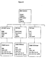
- Figure 7 is a block diagram depicting in more detail an exemplary embodiment of the hub 42 and direct circuit crossbar 44 arrangement of the present invention and its connection with a network interface unit 32 and set-top electronics 40.
- the direct circuit crossbar 44 and 42 selectively provide either a direct circuit between a particular network interface unit 32 and a set-top electronics 40, or a simple network connection through the hub 42 for these units.
- only portions of the network interface unit 32 and the set-top electronics 40 are depicted, for purposes of illustration and explanation.
- the hub 42 is a relatively simple and inexpensive hub, since it does not include any sort of packet routing switch or store and forward switch. There is no intelligence that examines the traffic and dynamically switches the hub according to the transmit and receive addresses as in hubs that have packet routing switches.
- any number of directly connected pairs may be connected by the direct circuit crossbar 44, depending on the size of the crossbar 44.
- the network interface unit 32 and the set-top electronics 40 are each shown with five pin positions or connections, each of the connections being a pair. This coincides with a conventional telephone plug, the telephone RJ45, which has ten pin positions.
- the internal network 34 provides the connection between the network interface units 32, the set-top electronics 40 and the direct circuit crossbar 44.
- the internal network 34 is 10 or 100base-T Ethernet.
- a microprocessor 110 serves as the controller for the direct circuit crossbar 44 and controls the positions of the switches 108 in response to user commands that require a direct circuit to perform. For example, a user may choose to watch a movie from a video on demand service and therefore makes this selection on a hand-held remote control.
- the microprocessor 110 in response to this selection, will then change the positions of the switches 108 to establish a direct circuit between the network interface unit 32 that is connected to the external network that carries the video on demand service, and the set-top electronics 40 that is coupled to the television receiver on which the user desires to view the movie.
- switch 108a is moved to its illustrated position to connect the transmit lines of transceiver 88 of the network interface unit 32 to line 112 of the direct circuit crossbar 44.
- the transmit lines of transceiver 88 are no longer connected to the network at the Tx1 port of the hub 42.
- the receive lines of the transceiver 92 of the set-top electronics 40 are connected through switch 108g to the same line 112 of the direct circuit crossbar 44.
- the direct circuit established by the direct circuit crossbar 44 provides an excellent pathway for data from the network interface unit 32 to the set-top electronics 40, it may occur that not all of the data coming into the network interface unit 32 is meant for the set-top electronics 40. For example, it is possible that e-mail is received over this particular network interface unit 32, and the homeowner wants e-mail to be directed to a personal computer, and not to a television. However, there is no connection to the network 34 due to the direct circuit once a direct circuit is established.
- the set-top electronics 40 examines the addresses of the data packets it receives and performs a routing function for data that is not meant for this set-top electronics 40.
- the data is re-routed by the set-top electronics 40 onto the network 34 through the hub 42.
- This re-routing by the end point connection avoids the need for the system to use an expensive and complicated router.
- the set-top electronics 40 has a microprocessor 120 and associated memory 122 to identify and route the data packets back to the network 34.
- the direct circuit between the network interface unit 32 and the set-top electronics 40 provides a jitter-free connection for video data, but the re-routing of other data into the network 34 through the hub allows more than one type of data to be carried into the home by the network interface unit 32.
- collision detection is required by the set-top electronics 40 to allow it to transmit to the hub 42.
- the set-top electronics 40 needs to learn of collisions and re-transmit the data to the network 34 if such collisions occur.
- the network interface unit 32 can be set, in certain embodiments, to disable collisions because they cannot occur on the direct circuit. However, in certain embodiments, in both the network interface unit port and the set-top electronics port (to the network 34 through the crossbar 44) , the same collision pair is included for convenience.
- one of the five pairs of wires is available to provide picture-in-picture capability for the system.
- the network interface unit 32 may provide a second stream of data through another transceiver 88a over a second pair of transmit wires onto a separate crossbar connection line 114.
- the set-top electronics 40 which has another transceiver 88a also connected to line 114, receives this second stream of data through the direct circuit to provide a picture-in-picture on a television screen.
- both pictures may be provided without jitter by separate direct circuits.
- the crossbar switches 108 are implemented by an analog MOS array of transistors, controlled in response to signals from the controller 110. This is exemplary only, however, as other embodiments employ switches of different design, as appreciated by one of ordinary skill in the art.
- the hub 42 is described as connected to the internal network.
- the hub 42 may also be logically considered as part of the internal network, or even forming the network, with the remaining wiring forming means for attaching end terminals to the hub 42.
- the logical distinctions depicted and described in the present specification are exemplary only.
- the separation of the network interface unit and the set-top electronics according to the present invention provides a relatively inexpensive connection of a multitude of devices to each other within the home, and to the outside world.
Landscapes
- Engineering & Computer Science (AREA)
- Computer Networks & Wireless Communication (AREA)
- Signal Processing (AREA)
- Automation & Control Theory (AREA)
- Multimedia (AREA)
- Small-Scale Networks (AREA)
- Data Exchanges In Wide-Area Networks (AREA)
- Vehicle Step Arrangements And Article Storage (AREA)
- Communication Control (AREA)
- Mobile Radio Communication Systems (AREA)
- Use Of Switch Circuits For Exchanges And Methods Of Control Of Multiplex Exchanges (AREA)
Claims (6)
- Dispositif de barrette croisée à circuit direct et de concentrateur pour utilisation dans un réseau numérique interne (34, 10), par exemple un réseau domestique, afin de connecter de manière sélective des terminaux finaux d'unités d'interface réseau (NIU, 32) et des terminaux finaux de produits informatiques (STE, 40, PC); lesdites unités d'interface réseau (NIU, 32) permettant une connexion entre ledit réseau numérique interne (34, 10) et un réseau externe, le dispositif de barrette croisée à circuit direct et de concentrateur étant caractérisé en ce qu'il comprend :une barrette croisée à circuit direct (44) qui est couplée à une pluralité desdits terminaux finaux desdites unités d'interface réseau (NIU, 32) et desdits produits informatiques (STE, 40, PC) afin de connecter de manière sélective deux terminaux finaux ensemble, établissant ainsi un circuit direct entre une unité d'interface réseau (NIU, 32) et un produit informatique (STE, 40, PC) ; etun concentrateur (42) qui n'a pas de circuits de routage de paquets, qui est couplé à ladite barrette croisée à circuit direct (44) et qui est configuré dans le but de connecter deux ou plus des terminaux finaux qui ne sont pas couplés de manière sélective par la barrette croisée à circuit direct (44) ; le concentrateur (42) communicant avec ledit réseau numérique interne grâce auquel chacun des terminaux finaux connectés au concentrateur (42) sont interconnectés.
- Dispositif selon la revendication 1, dans lequel la barrette croisée à circuit direct (44) dispose de lignes de circuit direct (112) et de commutateurs contrôlables (108) dans le but de connecter les deux terminaux finaux ensemble via les lignes de circuit direct (112).
- Dispositif selon la revendication 2, dans lequel la barrette croisée à circuit direct (44) dispose d'un processeur (110) qui répond aux signaux de commande afin de contrôler les commutateurs (108) dans le but de connecter les deux terminaux finaux ensemble via les lignes de circuit direct (112), dans lequel un circuit direct entre deux terminaux finaux est établi par connexion des terminaux finaux à la même ligne de circuit direct (112).
- Dispositif selon la revendication 3, dans lequel chacune des pluralités de terminaux finaux dispose de lignes de réception et de transmission, et dans lequel un circuit direct établi entre les deux terminaux finaux provoque que la ligne de transmission du premier des deux terminaux finaux est connectée à la même ligne de circuit direct (112) comme la ligne de réception du second des deux terminaux finaux, et la ligne de réception du premier des deux terminaux finaux ainsi que la ligne de transmission du second des deux terminaux finaux étant connectées au concentrateur (42).
- Dispositif selon la revendication 4, dans lequel les commutateurs (108) sont des commutateurs analogiques MOS.
- Méthode de connexion de manière sélective d'une pluralité de terminaux finaux d'unités d'interface réseau (NIU, 32) et de terminaux finaux de produits Informatiques (STE, 40, PC), étant caractérisée en ce qu'elle comprend :lesdites unités d'interface réseau (NIU, 32) permettant une connexion entre ledit réseau numérique interne (34, 10) et un réseau externe.la connexion des ports de réception et de transmission (Rx, Tx) d'au moins deux desdits terminaux finaux desdites unités d'interface réseau (NIU, 32) et desdits produits informatiques (STE, 40, PC) à un concentrateur (42) ne disposant pas de circuits de routage de paquets, dans laquelle les deux terminaux finaux sont interconnectés via le concentrateur (42) afin de communiquer avec un réseau numérique interne ;la connexion directe de manière sélective au moins du port de transmission (Tx, Rx) d'un premier des terminaux finaux au port de réception d'un second des deux terminaux finaux par une barrette croisée à circuit direct (40) afin d'établir un circuit direct entre le premier et le second des deux terminaux finaux et la déconnexion des ports de transmission du premier des deux terminaux finaux du concentrateur ainsi que le port de réception du second des deux terminaux finaux du concentrateur (42) ;
Applications Claiming Priority (3)
| Application Number | Priority Date | Filing Date | Title |
|---|---|---|---|
| US561534 | 1995-11-22 | ||
| US08/561,534 US5579308A (en) | 1995-11-22 | 1995-11-22 | Crossbar/hub arrangement for multimedia network |
| PCT/US1996/018800 WO1997019566A2 (fr) | 1995-11-22 | 1996-11-21 | Accessoire barrette croisee/plot destine a un reseau multimedia |
Publications (3)
| Publication Number | Publication Date |
|---|---|
| EP0862843A2 EP0862843A2 (fr) | 1998-09-09 |
| EP0862843A3 EP0862843A3 (fr) | 2004-08-25 |
| EP0862843B1 true EP0862843B1 (fr) | 2004-08-25 |
Family
ID=24242367
Family Applications (1)
| Application Number | Title | Priority Date | Filing Date |
|---|---|---|---|
| EP96940860A Expired - Lifetime EP0862843B1 (fr) | 1995-11-22 | 1996-11-21 | Accessoire barrette croisee/plot destine a un reseau multimedia |
Country Status (13)
| Country | Link |
|---|---|
| US (1) | US5579308A (fr) |
| EP (1) | EP0862843B1 (fr) |
| JP (1) | JP3920342B2 (fr) |
| KR (1) | KR100418303B1 (fr) |
| CN (1) | CN1096819C (fr) |
| AT (1) | ATE274783T1 (fr) |
| CA (1) | CA2238280C (fr) |
| DE (1) | DE69633249T2 (fr) |
| ES (1) | ES2225902T3 (fr) |
| IL (1) | IL124604A (fr) |
| PT (1) | PT862843E (fr) |
| TW (1) | TW311310B (fr) |
| WO (1) | WO1997019566A2 (fr) |
Families Citing this family (88)
| Publication number | Priority date | Publication date | Assignee | Title |
|---|---|---|---|---|
| US5844596A (en) | 1989-07-14 | 1998-12-01 | Inline Connection Corporation | Two-way RF communication at points of convergence of wire pairs from separate internal telephone networks |
| US10361802B1 (en) | 1999-02-01 | 2019-07-23 | Blanding Hovenweep, Llc | Adaptive pattern recognition based control system and method |
| JP2770782B2 (ja) * | 1995-05-31 | 1998-07-02 | 日本電気株式会社 | Lan間接続装置 |
| US5886732A (en) * | 1995-11-22 | 1999-03-23 | Samsung Information Systems America | Set-top electronics and network interface unit arrangement |
| US5722041A (en) * | 1995-12-05 | 1998-02-24 | Altec Lansing Technologies, Inc. | Hybrid home-entertainment system |
| US5793235A (en) * | 1996-02-13 | 1998-08-11 | Hughes Electronics Corporation | Circuit for improving timing conditions in a data processing unit |
| US5978364A (en) * | 1996-02-29 | 1999-11-02 | Philips Electronics North America Corporation | Method for routing data packets within a wireless, packet-hopping network and a wireless network for implementing the same |
| CA2185053C (fr) * | 1996-06-24 | 2002-04-16 | Frank B. Norman | Canal de retour interactif pour systeme de diffusion directe par satellite |
| CA2262859A1 (fr) * | 1996-07-12 | 1998-01-22 | David D. Goodman | Systeme de communication numerique destine aux immeubles residentiels ou a des structures similaires et qui utilise les cables telephoniques existants |
| US6622304B1 (en) | 1996-09-09 | 2003-09-16 | Thomas W. Carhart | Interface system for computing apparatus and communications stations |
| US5963561A (en) * | 1996-12-05 | 1999-10-05 | At&T Corp. | Method and apparatus for bandwidth reuse in a communication network |
| US5905716A (en) * | 1996-12-09 | 1999-05-18 | Ericsson, Inc. | Asynchronous full duplex communications over a single channel |
| US6032118A (en) | 1996-12-19 | 2000-02-29 | Northern Telecom Limited | Virtual private network service provider for asynchronous transfer mode network |
| US6157673A (en) * | 1996-12-26 | 2000-12-05 | Philips Electronics North America Corp. | Fast extraction of program specific information from multiple transport streams |
| US20030192053A1 (en) * | 1997-02-19 | 2003-10-09 | Next Level Communications, Inc. | Method and apparatus for transmitting wireless signals over media |
| US20040083493A1 (en) * | 1997-02-19 | 2004-04-29 | Next Level Communications, Inc. | Transmitting caller ID within a digital stream |
| US6008777A (en) * | 1997-03-07 | 1999-12-28 | Intel Corporation | Wireless connectivity between a personal computer and a television |
| EP0968610B1 (fr) * | 1997-03-21 | 2002-11-06 | Canal+ Technologies | Transmission et reception de programmes televises et d'autres donnees |
| GB2326306B (en) * | 1997-06-14 | 2002-06-12 | Northern Telecom Ltd | Telecommunications network |
| KR100268498B1 (ko) | 1997-06-26 | 2000-10-16 | 윤종용 | 셋탑박스를이용한pc통신및인터넷서비스장치와그방법 |
| US6192399B1 (en) | 1997-07-11 | 2001-02-20 | Inline Connections Corporation | Twisted pair communication system |
| ZA987179B (en) * | 1997-09-05 | 1999-04-23 | Worldspace Management Corp | System for bradcasting information from the internet using satellite direct digital broadcast system and selectively downloading information at user terminals |
| JP3733218B2 (ja) * | 1997-09-30 | 2006-01-11 | キヤノン株式会社 | 中継装置及びその制御方法及び記憶媒体 |
| US5953503A (en) * | 1997-10-29 | 1999-09-14 | Digital Equipment Corporation | Compression protocol with multiple preset dictionaries |
| US6216157B1 (en) * | 1997-11-14 | 2001-04-10 | Yahoo! Inc. | Method and apparatus for a client-server system with heterogeneous clients |
| US6108696A (en) * | 1997-11-14 | 2000-08-22 | Online Anywhere | Method and apparatus to connect a general purpose computer to a special purpose system |
| US20030131358A1 (en) * | 1997-11-18 | 2003-07-10 | Gerard Busch | System and process for accessing digital data on a video network |
| DK1084576T3 (da) * | 1998-05-07 | 2005-11-28 | Samsung Electronics Co Ltd | Fremgangsmåde og apparat for universelt tilgængelige kommando- og kontrolinformationer i et netværk |
| US7043532B1 (en) | 1998-05-07 | 2006-05-09 | Samsung Electronics Co., Ltd. | Method and apparatus for universally accessible command and control information in a network |
| US6505255B1 (en) | 1999-04-29 | 2003-01-07 | Mitsubishi Electric Information Technology Center America, Inc. (Ita) | Method for formatting and routing data between an external network and an internal network |
| US6496862B1 (en) | 1998-08-25 | 2002-12-17 | Mitsubishi Electric Research Laboratories, Inc. | Remote monitoring and control of devices connected to an IEEE 1394 bus via a gateway device |
| US6614781B1 (en) | 1998-11-20 | 2003-09-02 | Level 3 Communications, Inc. | Voice over data telecommunications network architecture |
| US6442169B1 (en) | 1998-11-20 | 2002-08-27 | Level 3 Communications, Inc. | System and method for bypassing data from egress facilities |
| US7415102B2 (en) * | 1999-01-22 | 2008-08-19 | Pointset Corporation | Method and apparatus for setting programmable features of an appliance |
| US7904187B2 (en) | 1999-02-01 | 2011-03-08 | Hoffberg Steven M | Internet appliance system and method |
| GB2350036A (en) * | 1999-03-03 | 2000-11-15 | Samsung Inf Syst America | Multimedia home network architecture |
| JP2000278654A (ja) * | 1999-03-26 | 2000-10-06 | Sony Corp | 音声及び/または映像信号の伝送システム、その送信装置、及びその受信装置 |
| US6523177B1 (en) * | 1999-04-01 | 2003-02-18 | Scientific-Atlanta, Inc. | Cable television system with digital reverse path architecture |
| US7127734B1 (en) | 1999-04-12 | 2006-10-24 | Texas Instruments Incorporated | System and methods for home network communications |
| US6633547B1 (en) | 1999-04-29 | 2003-10-14 | Mitsubishi Electric Research Laboratories, Inc. | Command and control transfer |
| US6378000B1 (en) | 1999-04-29 | 2002-04-23 | Mitsubish Electric Research Laboratories, Inc | Address mapping in home entertainment network |
| US6523064B1 (en) | 1999-04-29 | 2003-02-18 | Mitsubishi Electric Research Laboratories, Inc | Network gateway for collecting geographic data information |
| US6469743B1 (en) | 1999-06-09 | 2002-10-22 | International Business Machines Corporation | Programmable external graphics/video port for digital video decode system chip |
| AU6953500A (en) * | 1999-07-08 | 2001-01-30 | Next Level Communications L.P. | Wireless and xdsl residential gateway and system |
| US6801507B1 (en) | 1999-07-27 | 2004-10-05 | Samsung Electronics Co., Ltd. | Device discovery and configuration in a home network |
| US7490293B1 (en) | 1999-07-27 | 2009-02-10 | Samsung Electronics Co., Ltd. | Device discovery and control in a bridged home network |
| US7610559B1 (en) * | 1999-07-27 | 2009-10-27 | Samsung Electronics Co., Ltd. | Device customized home network top-level information architecture |
| US8032833B1 (en) | 1999-07-27 | 2011-10-04 | Samsung Electronics Co., Ltd. | Home network device information architecture |
| US6690657B1 (en) | 2000-02-25 | 2004-02-10 | Berkeley Concept Research Corporation | Multichannel distributed wireless repeater network |
| US7200683B1 (en) * | 1999-08-17 | 2007-04-03 | Samsung Electronics, Co., Ltd. | Device communication and control in a home network connected to an external network |
| AU3969101A (en) * | 1999-11-08 | 2001-06-04 | Qwest Communications International Inc. | Digital headend and full service network for distribution of video and audio programming |
| AU2059801A (en) | 1999-12-03 | 2001-06-12 | Ourworld Live, Inc. | Consumer access systems and methods for providing same |
| US6898210B1 (en) * | 1999-12-23 | 2005-05-24 | 3Com Corporation | System and method for providing a local area network utilizing remote transceivers |
| US7324635B2 (en) | 2000-05-04 | 2008-01-29 | Telemaze Llc | Branch calling and caller ID based call routing telephone features |
| US7068596B1 (en) | 2000-07-07 | 2006-06-27 | Nevco Technology, Inc. | Interactive data transmission system having staged servers |
| US7349967B2 (en) * | 2000-07-21 | 2008-03-25 | Samsung Electronics Co., Ltd. | Architecture for home network on world wide web with private-public IP address/URL mapping |
| US8127326B2 (en) | 2000-11-14 | 2012-02-28 | Claussen Paul J | Proximity detection using wireless connectivity in a communications system |
| WO2002047388A2 (fr) | 2000-11-14 | 2002-06-13 | Scientific-Atlanta, Inc. | Distribution de signaux de television pour abonne en reseau |
| US7050109B2 (en) * | 2001-03-02 | 2006-05-23 | General Instrument Corporation | Methods and apparatus for the provision of user selected advanced close captions |
| US20020146125A1 (en) * | 2001-03-14 | 2002-10-10 | Ahmet Eskicioglu | CA system for broadcast DTV using multiple keys for different service providers and service areas |
| GB2375466A (en) * | 2001-05-09 | 2002-11-13 | Ian Paul Rees | System for connecting viewing stations |
| US7610602B2 (en) * | 2001-05-23 | 2009-10-27 | The Directv Group, Inc. | Method, system and computer program product for aircraft multimedia distribution |
| US20030005460A1 (en) | 2001-07-01 | 2003-01-02 | David Bartholomew | Method and system for a low cost wireless telephone link for a set top box |
| US20030005450A1 (en) * | 2001-07-01 | 2003-01-02 | Gordon Smith | Method and system for connecting high speed data communication signals to a residentual gateway |
| CA2447876C (fr) * | 2001-08-22 | 2007-05-15 | Avocent Corporation | Commutateur de matrices semi-duplex a autosyncronisation |
| GB2384412B (en) * | 2001-10-12 | 2006-04-12 | Vortex Comm Ltd | Information supply system |
| US8763046B2 (en) * | 2001-12-03 | 2014-06-24 | Thomson Licensing | DBS feature extension architecture |
| US20030185301A1 (en) * | 2002-04-02 | 2003-10-02 | Abrams Thomas Algie | Video appliance |
| US7516470B2 (en) | 2002-08-02 | 2009-04-07 | Cisco Technology, Inc. | Locally-updated interactive program guide |
| US7908625B2 (en) | 2002-10-02 | 2011-03-15 | Robertson Neil C | Networked multimedia system |
| US20040068753A1 (en) * | 2002-10-02 | 2004-04-08 | Robertson Neil C. | Video transmission systems and methods for a home network |
| US7545935B2 (en) | 2002-10-04 | 2009-06-09 | Scientific-Atlanta, Inc. | Networked multimedia overlay system |
| US7360235B2 (en) | 2002-10-04 | 2008-04-15 | Scientific-Atlanta, Inc. | Systems and methods for operating a peripheral record/playback device in a networked multimedia system |
| US8046806B2 (en) | 2002-10-04 | 2011-10-25 | Wall William E | Multiroom point of deployment module |
| FR2848343B1 (fr) * | 2002-12-05 | 2006-08-04 | France Telecom | Systeme d'interconnexion d'equipements terminaux au sein d'une installation terminale cuivre |
| US7487532B2 (en) | 2003-01-15 | 2009-02-03 | Cisco Technology, Inc. | Optimization of a full duplex wideband communications system |
| US8094640B2 (en) | 2003-01-15 | 2012-01-10 | Robertson Neil C | Full duplex wideband communications system for a local coaxial network |
| US20040184746A1 (en) * | 2003-03-17 | 2004-09-23 | Chang Chin L. | Fiber optic connector extension for transmission of digital video data |
| US20040244040A1 (en) * | 2003-06-02 | 2004-12-02 | Vickers Walter Andrew | Remote cable system |
| US7171506B2 (en) * | 2003-11-17 | 2007-01-30 | Sony Corporation | Plural interfaces in home network with first component having a first host bus width and second component having second bus width |
| US20050194456A1 (en) | 2004-03-02 | 2005-09-08 | Tessier Patrick C. | Wireless controller with gateway |
| US8543723B2 (en) * | 2004-07-27 | 2013-09-24 | Sony Corporation | Home network system with transmission error recovery |
| KR100696948B1 (ko) * | 2005-07-28 | 2007-03-20 | 전자부품연구원 | 직렬 스위치 기반의 홈 게이트웨이 장치 및 홈 네트워크시스템 |
| US7876998B2 (en) | 2005-10-05 | 2011-01-25 | Wall William E | DVD playback over multi-room by copying to HDD |
| US20070143801A1 (en) * | 2005-12-20 | 2007-06-21 | Madonna Robert P | System and method for a programmable multimedia controller |
| US20080247401A1 (en) * | 2007-04-06 | 2008-10-09 | Texas Instruments Incorporated | Remote Access to Home Communication Services |
| JP5501052B2 (ja) * | 2010-03-24 | 2014-05-21 | キヤノン株式会社 | 通信装置、通信装置の制御方法、プログラム |
| US20120324516A1 (en) * | 2011-06-14 | 2012-12-20 | Mediatek Singapore Pte. Ltd. | Method and system to provide a consumer electronics system with improved functionality |
Family Cites Families (7)
| Publication number | Priority date | Publication date | Assignee | Title |
|---|---|---|---|---|
| DE2514012C2 (de) * | 1975-03-29 | 1979-09-27 | Licentia Patent-Verwaltungs-Gmbh, 6000 Frankfurt | Monolithisch integrierte halbleiterschaltungsanordnung, insbesondere fuer koppelbausteine von vermittlungssystemen |
| NL8000529A (nl) * | 1980-01-29 | 1981-08-17 | Philips Nv | Schakelmatrix. |
| JPH03123244A (ja) * | 1989-10-06 | 1991-05-27 | Matsushita Electric Ind Co Ltd | 通信装置 |
| DE4002862A1 (de) * | 1990-02-01 | 1991-08-08 | Standard Elektrik Lorenz Ag | Breitbandnebenstellenanlage |
| US5140585A (en) * | 1990-07-19 | 1992-08-18 | Kabushiki Kaisha Toshiba | Star local-area network system |
| US5452291A (en) * | 1993-11-30 | 1995-09-19 | Panasonic Technologies, Inc. | Combination brouter and cluster controller |
| US5485630A (en) * | 1994-03-31 | 1996-01-16 | Panasonic Technologies, Inc. | Audio/video distribution system |
-
1995
- 1995-11-22 US US08/561,534 patent/US5579308A/en not_active Expired - Lifetime
-
1996
- 1996-11-20 TW TW085114294A patent/TW311310B/zh active
- 1996-11-21 ES ES96940860T patent/ES2225902T3/es not_active Expired - Lifetime
- 1996-11-21 EP EP96940860A patent/EP0862843B1/fr not_active Expired - Lifetime
- 1996-11-21 AT AT96940860T patent/ATE274783T1/de not_active IP Right Cessation
- 1996-11-21 IL IL12460496A patent/IL124604A/xx not_active IP Right Cessation
- 1996-11-21 JP JP51993697A patent/JP3920342B2/ja not_active Expired - Fee Related
- 1996-11-21 DE DE69633249T patent/DE69633249T2/de not_active Expired - Lifetime
- 1996-11-21 WO PCT/US1996/018800 patent/WO1997019566A2/fr active IP Right Grant
- 1996-11-21 PT PT96940860T patent/PT862843E/pt unknown
- 1996-11-21 KR KR10-1998-0703921A patent/KR100418303B1/ko not_active IP Right Cessation
- 1996-11-21 CN CN96199742A patent/CN1096819C/zh not_active Expired - Fee Related
- 1996-11-21 CA CA002238280A patent/CA2238280C/fr not_active Expired - Fee Related
Also Published As
| Publication number | Publication date |
|---|---|
| DE69633249D1 (de) | 2004-09-30 |
| PT862843E (pt) | 2004-12-31 |
| WO1997019566A3 (fr) | 2001-06-14 |
| IL124604A0 (en) | 1998-12-06 |
| ES2225902T3 (es) | 2005-03-16 |
| IL124604A (en) | 2003-07-31 |
| CA2238280A1 (fr) | 1997-05-29 |
| WO1997019566A2 (fr) | 1997-05-29 |
| TW311310B (fr) | 1997-07-21 |
| DE69633249T2 (de) | 2005-08-25 |
| US5579308A (en) | 1996-11-26 |
| CA2238280C (fr) | 2003-05-06 |
| EP0862843A3 (fr) | 2004-08-25 |
| JP2001501044A (ja) | 2001-01-23 |
| CN1207862A (zh) | 1999-02-10 |
| KR100418303B1 (ko) | 2004-06-24 |
| ATE274783T1 (de) | 2004-09-15 |
| CN1096819C (zh) | 2002-12-18 |
| KR19990071645A (ko) | 1999-09-27 |
| JP3920342B2 (ja) | 2007-05-30 |
| EP0862843A2 (fr) | 1998-09-09 |
Similar Documents
| Publication | Publication Date | Title |
|---|---|---|
| EP0862843B1 (fr) | Accessoire barrette croisee/plot destine a un reseau multimedia | |
| EP0862842B1 (fr) | Configuration de coffret d'abonne et d'unite d'interface de reseau | |
| US6005861A (en) | Home multimedia network architecture | |
| US5940387A (en) | Home multimedia network architecture | |
| EP0862832B1 (fr) | Procede et appareil permettant de recuperer l'horloge de signaux mpeg | |
| KR100317858B1 (ko) | 홈 멀티미디어 네트웍 구조 | |
| KR20010006688A (ko) | 데이터 스트림 클록 복구 방법 및 장치 | |
| MXPA98004144A (en) | Crossbarhub arrangement for multimedia network | |
| MXPA98004095A (en) | Architecture of multimedia network for ho |
Legal Events
| Date | Code | Title | Description |
|---|---|---|---|
| PUAI | Public reference made under article 153(3) epc to a published international application that has entered the european phase |
Free format text: ORIGINAL CODE: 0009012 |
|
| 17P | Request for examination filed |
Effective date: 19980622 |
|
| AK | Designated contracting states |
Kind code of ref document: A2 Designated state(s): AT BE CH DE DK ES FI FR GB GR IE IT LI LU MC NL PT SE |
|
| RAP1 | Party data changed (applicant data changed or rights of an application transferred) |
Owner name: SAMSUNG ELECTRONICS CO., LTD. |
|
| 17Q | First examination report despatched |
Effective date: 20030305 |
|
| GRAP | Despatch of communication of intention to grant a patent |
Free format text: ORIGINAL CODE: EPIDOSNIGR1 |
|
| GRAS | Grant fee paid |
Free format text: ORIGINAL CODE: EPIDOSNIGR3 |
|
| GRAA | (expected) grant |
Free format text: ORIGINAL CODE: 0009210 |
|
| PUAK | Availability of information related to the publication of the international search report |
Free format text: ORIGINAL CODE: 0009015 |
|
| AK | Designated contracting states |
Kind code of ref document: B1 Designated state(s): AT BE CH DE DK ES FI FR GB GR IE IT LI LU MC NL PT SE Kind code of ref document: A3 Designated state(s): AT BE CH DE DK ES FI FR GB GR IE IT LI LU MC NL PT SE |
|
| REG | Reference to a national code |
Ref country code: GB Ref legal event code: FG4D |
|
| REG | Reference to a national code |
Ref country code: CH Ref legal event code: EP |
|
| REG | Reference to a national code |
Ref country code: IE Ref legal event code: FG4D |
|
| REF | Corresponds to: |
Ref document number: 69633249 Country of ref document: DE Date of ref document: 20040930 Kind code of ref document: P |
|
| REG | Reference to a national code |
Ref country code: CH Ref legal event code: NV Representative=s name: ISLER & PEDRAZZINI AG |
|
| REG | Reference to a national code |
Ref country code: SE Ref legal event code: TRGR |
|
| REG | Reference to a national code |
Ref country code: DK Ref legal event code: T3 |
|
| REG | Reference to a national code |
Ref country code: GR Ref legal event code: EP Ref document number: 20040403800 Country of ref document: GR |
|
| REG | Reference to a national code |
Ref country code: PT Ref legal event code: SC4A Free format text: AVAILABILITY OF NATIONAL TRANSLATION Effective date: 20041108 |
|
| REG | Reference to a national code |
Ref country code: ES Ref legal event code: FG2A Ref document number: 2225902 Country of ref document: ES Kind code of ref document: T3 |
|
| ET | Fr: translation filed | ||
| PLBE | No opposition filed within time limit |
Free format text: ORIGINAL CODE: 0009261 |
|
| STAA | Information on the status of an ep patent application or granted ep patent |
Free format text: STATUS: NO OPPOSITION FILED WITHIN TIME LIMIT |
|
| 26N | No opposition filed |
Effective date: 20050526 |
|
| REG | Reference to a national code |
Ref country code: CH Ref legal event code: PCAR Free format text: ISLER & PEDRAZZINI AG;POSTFACH 1772;8027 ZUERICH (CH) |
|
| PGFP | Annual fee paid to national office [announced via postgrant information from national office to epo] |
Ref country code: SE Payment date: 20091106 Year of fee payment: 14 Ref country code: MC Payment date: 20091111 Year of fee payment: 14 Ref country code: LU Payment date: 20091118 Year of fee payment: 14 Ref country code: IE Payment date: 20091113 Year of fee payment: 14 Ref country code: FI Payment date: 20091112 Year of fee payment: 14 Ref country code: ES Payment date: 20091201 Year of fee payment: 14 Ref country code: DK Payment date: 20091117 Year of fee payment: 14 Ref country code: DE Payment date: 20091119 Year of fee payment: 14 Ref country code: CH Payment date: 20091113 Year of fee payment: 14 Ref country code: AT Payment date: 20091111 Year of fee payment: 14 |
|
| PGFP | Annual fee paid to national office [announced via postgrant information from national office to epo] |
Ref country code: NL Payment date: 20091104 Year of fee payment: 14 |
|
| PGFP | Annual fee paid to national office [announced via postgrant information from national office to epo] |
Ref country code: PT Payment date: 20091104 Year of fee payment: 14 |
|
| PGFP | Annual fee paid to national office [announced via postgrant information from national office to epo] |
Ref country code: IT Payment date: 20091113 Year of fee payment: 14 Ref country code: GB Payment date: 20091118 Year of fee payment: 14 Ref country code: FR Payment date: 20091123 Year of fee payment: 14 |
|
| PGFP | Annual fee paid to national office [announced via postgrant information from national office to epo] |
Ref country code: GR Payment date: 20091112 Year of fee payment: 14 Ref country code: BE Payment date: 20091130 Year of fee payment: 14 |
|
| REG | Reference to a national code |
Ref country code: PT Ref legal event code: MM4A Free format text: LAPSE DUE TO NON-PAYMENT OF FEES Effective date: 20110523 |
|
| BERE | Be: lapsed |
Owner name: *SAMSUNG ELECTRONICS CO. LTD Effective date: 20101130 |
|
| REG | Reference to a national code |
Ref country code: NL Ref legal event code: V1 Effective date: 20110601 |
|
| REG | Reference to a national code |
Ref country code: SE Ref legal event code: EUG |
|
| PG25 | Lapsed in a contracting state [announced via postgrant information from national office to epo] |
Ref country code: MC Free format text: LAPSE BECAUSE OF NON-PAYMENT OF DUE FEES Effective date: 20101130 |
|
| REG | Reference to a national code |
Ref country code: CH Ref legal event code: PL |
|
| REG | Reference to a national code |
Ref country code: DK Ref legal event code: EBP |
|
| GBPC | Gb: european patent ceased through non-payment of renewal fee |
Effective date: 20101121 |
|
| PG25 | Lapsed in a contracting state [announced via postgrant information from national office to epo] |
Ref country code: CH Free format text: LAPSE BECAUSE OF NON-PAYMENT OF DUE FEES Effective date: 20101130 Ref country code: GR Free format text: LAPSE BECAUSE OF NON-PAYMENT OF DUE FEES Effective date: 20110602 Ref country code: LI Free format text: LAPSE BECAUSE OF NON-PAYMENT OF DUE FEES Effective date: 20101130 Ref country code: PT Free format text: LAPSE BECAUSE OF NON-PAYMENT OF DUE FEES Effective date: 20110523 |
|
| REG | Reference to a national code |
Ref country code: FR Ref legal event code: ST Effective date: 20110801 |
|
| PG25 | Lapsed in a contracting state [announced via postgrant information from national office to epo] |
Ref country code: AT Free format text: LAPSE BECAUSE OF NON-PAYMENT OF DUE FEES Effective date: 20101121 Ref country code: NL Free format text: LAPSE BECAUSE OF NON-PAYMENT OF DUE FEES Effective date: 20110601 Ref country code: FI Free format text: LAPSE BECAUSE OF NON-PAYMENT OF DUE FEES Effective date: 20101121 Ref country code: BE Free format text: LAPSE BECAUSE OF NON-PAYMENT OF DUE FEES Effective date: 20101130 |
|
| REG | Reference to a national code |
Ref country code: IE Ref legal event code: MM4A |
|
| REG | Reference to a national code |
Ref country code: DE Ref legal event code: R119 Ref document number: 69633249 Country of ref document: DE Effective date: 20110601 Ref country code: DE Ref legal event code: R119 Ref document number: 69633249 Country of ref document: DE Effective date: 20110531 |
|
| PG25 | Lapsed in a contracting state [announced via postgrant information from national office to epo] |
Ref country code: DE Free format text: LAPSE BECAUSE OF NON-PAYMENT OF DUE FEES Effective date: 20110531 Ref country code: SE Free format text: LAPSE BECAUSE OF NON-PAYMENT OF DUE FEES Effective date: 20101122 |
|
| PG25 | Lapsed in a contracting state [announced via postgrant information from national office to epo] |
Ref country code: DK Free format text: LAPSE BECAUSE OF NON-PAYMENT OF DUE FEES Effective date: 20101130 Ref country code: IE Free format text: LAPSE BECAUSE OF NON-PAYMENT OF DUE FEES Effective date: 20101122 Ref country code: FR Free format text: LAPSE BECAUSE OF NON-PAYMENT OF DUE FEES Effective date: 20101130 |
|
| PG25 | Lapsed in a contracting state [announced via postgrant information from national office to epo] |
Ref country code: GB Free format text: LAPSE BECAUSE OF NON-PAYMENT OF DUE FEES Effective date: 20101121 |
|
| PG25 | Lapsed in a contracting state [announced via postgrant information from national office to epo] |
Ref country code: IT Free format text: LAPSE BECAUSE OF NON-PAYMENT OF DUE FEES Effective date: 20101121 |
|
| REG | Reference to a national code |
Ref country code: ES Ref legal event code: FD2A Effective date: 20120110 |
|
| PG25 | Lapsed in a contracting state [announced via postgrant information from national office to epo] |
Ref country code: ES Free format text: LAPSE BECAUSE OF NON-PAYMENT OF DUE FEES Effective date: 20101122 |
|
| PG25 | Lapsed in a contracting state [announced via postgrant information from national office to epo] |
Ref country code: LU Free format text: LAPSE BECAUSE OF NON-PAYMENT OF DUE FEES Effective date: 20101121 |