EP0862683B1 - Procede pour effectuer une diagraphie de puits de forage - Google Patents
Procede pour effectuer une diagraphie de puits de forage Download PDFInfo
- Publication number
- EP0862683B1 EP0862683B1 EP96939904A EP96939904A EP0862683B1 EP 0862683 B1 EP0862683 B1 EP 0862683B1 EP 96939904 A EP96939904 A EP 96939904A EP 96939904 A EP96939904 A EP 96939904A EP 0862683 B1 EP0862683 B1 EP 0862683B1
- Authority
- EP
- European Patent Office
- Prior art keywords
- earth
- parameter
- uncertainty
- borehole
- uncertainties
- Prior art date
- Legal status (The legal status is an assumption and is not a legal conclusion. Google has not performed a legal analysis and makes no representation as to the accuracy of the status listed.)
- Expired - Lifetime
Links
- 238000000034 method Methods 0.000 title claims description 29
- 238000005259 measurement Methods 0.000 claims description 25
- 230000005484 gravity Effects 0.000 claims description 10
- 230000015572 biosynthetic process Effects 0.000 claims description 5
- 239000007787 solid Substances 0.000 claims description 4
- 238000010586 diagram Methods 0.000 description 6
- 238000012937 correction Methods 0.000 description 3
- 230000001133 acceleration Effects 0.000 description 2
- 238000005553 drilling Methods 0.000 description 2
- 239000004215 Carbon black (E152) Substances 0.000 description 1
- 238000013459 approach Methods 0.000 description 1
- 230000001419 dependent effect Effects 0.000 description 1
- 229930195733 hydrocarbon Natural products 0.000 description 1
- 150000002430 hydrocarbons Chemical class 0.000 description 1
- 238000012545 processing Methods 0.000 description 1
Images

Classifications
-
- E—FIXED CONSTRUCTIONS
- E21—EARTH OR ROCK DRILLING; MINING
- E21B—EARTH OR ROCK DRILLING; OBTAINING OIL, GAS, WATER, SOLUBLE OR MELTABLE MATERIALS OR A SLURRY OF MINERALS FROM WELLS
- E21B47/00—Survey of boreholes or wells
- E21B47/02—Determining slope or direction
- E21B47/022—Determining slope or direction of the borehole, e.g. using geomagnetism
Definitions
- the present invention relates to a method of qualifying a survey of a borehole formed in an earth formation.
- Such measurements can be conducted by using the earth gravity field and the earth magnetic field as references, for which purpose accelerometers and magnetometers are incorporated in the drill string, at regular mutual distances.
- accelerometers and magnetometers are incorporated in the drill string, at regular mutual distances.
- a second, independent, measurement is generally considered necessary.
- the independent measurement is commonly carried out using a gyroscope which is lowered into the borehole after setting of casing in the borehole. Such procedure is costly and time consuming, and it would be desirable to provide a method which obviates the need for conducting independent gyroscopic measurements.
- EP-A-0 384 537 discloses a method for surveying a borehole whereby directional data of the logged borehole are computed on the basis of earth field parameters measured by downhole sensors. To improve accuracy, expected values of the earth gravitational field intensity, earth magnetic field intensity and earth magnetic dip angle are used in the method of Lagrange multipliers to impose a three constraint fit on accelerometer and magnetometer reading.
- EP-A-0 654 686 discloses a method whereby nominal magnetic field strength and nominal dip angle are used in combination with sensor readings to yield the best estimate of the axial component of the magnetic field, which best estimate is used for calculating the borehole azimuth.
- a method of qualifying a survey of a borehole formed in an earth formation comprising:
- the earth field parameter can, for example, be the earth gravity or the earth magnetic field strength
- the borehole position parameter can, for example, be the borehole inclination or the borehole azimuth.
- the ratio of the difference between the measured earth field parameter and a known magnitude of said earth field parameter at said position, and the theoretical measurement uncertainty of the position parameter forms a preliminary check on the quality of the survey. If the measured earth field parameter is within the measurement tolerance of this parameter, i.e. if the ratio does not exceed the magnitude 1, then the survey is at least of acceptable quality. If the ratio exceeds magnitude 1, the survey is considered to be of poor quality. Thus the ratio forms a preliminary measure for the quality of the survey, and the product of this ratio and the theoretical measurement uncertainty of the position parameter (as determined in step d) forms the best guess of the survey quality.
- a solid state magnetic survey tool 1 which is suitable for use in the method according to the invention.
- the tool includes a plurality of sensors in the form of a triad of accelerometers 3 and a triad of magnetometers 5 whereby for ease of reference the individual accelerometers and magnetometers are not indicated, only their respective mutual orthogonal directions of measurement X, Y and Z have been indicated.
- the triad of accelerometers measure acceleration components and the triad of magnetometers 5 measure magnetic field components in these directions.
- the tool 1 has a longitudinal axis 7 which coincides with the longitudinal axis of a borehole (not shown) in which the tool 1 has been lowered.
- the high side direction of the tool 1 in the borehole is indicated as H.
- the tool 1 is incorporated in a drill string (not shown) which is used to deepen the borehole.
- the tool 1 is operated so as to measure the components in X, Y and Z directions of the earth gravity field G and the earth magnetic field B. From the measured components of G and B, the magnitudes of the magnetic field dip-angle D, the borehole inclination I and the borehole azimuth A are determined in a manner well-known in the art.
- the theoretical uncertainties of G, B, D, I and A are determined on the basis of calibration data representing the class of sensors to which the sensors of the tool 1 pertains (i.e.
- a preliminary assessment of the quality of the survey is achieved by comparing the differences between the corrected measured values and the known values of the earth field parameters G, B and D with the measurement uncertainties of G, B and D referred to above. For a survey to be of acceptable quality, said difference should not exceed the measurement uncertainty.
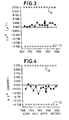
- Figs. 2, 3 and 4 example results of a borehole survey are shown.
- Fig. 2 shows a diagram of the difference ⁇ G m between the corrected measured value and the known value of G, against the along borehole depth.
- Fig. 3 shows a diagram of the difference ⁇ B m between the corrected measured value and the known value of B, against the along borehole depth.
- Fig. 4 shows a diagram of the difference ⁇ D m between the corrected measured value and the known value of D, against the along borehole depth.
- the measurement uncertainties of the earth field parameters in this example are:
- the lateral position uncertainties and the upward position uncertainties thus determined are then compared with the theoretical lateral and upward position uncertainties (derived from the theoretical inclination and azimuth uncertainties) to provide an indicator of the quality of the borehole survey.
Landscapes
- Geology (AREA)
- Mining & Mineral Resources (AREA)
- Life Sciences & Earth Sciences (AREA)
- Engineering & Computer Science (AREA)
- Physics & Mathematics (AREA)
- General Life Sciences & Earth Sciences (AREA)
- Geophysics (AREA)
- Fluid Mechanics (AREA)
- Environmental & Geological Engineering (AREA)
- Geochemistry & Mineralogy (AREA)
- Geophysics And Detection Of Objects (AREA)
- Measuring Magnetic Variables (AREA)
- Investigation Of Foundation Soil And Reinforcement Of Foundation Soil By Compacting Or Drainage (AREA)
- Earth Drilling (AREA)
- Paper (AREA)
Claims (13)
- Procédé de contrôle de la qualité d'une diagraphie d'un puits de forage formé dans une formation de terrain, le procédé comportant les étapes consistant à:a) sélectionner un capteur pour mesurer dans ledit puits de forage un paramètre du champ terrestre et un paramètre de position dans ledit puits de forage;b) déterminer les incertitudes théoriques sur la mesure desdits paramètres lorsqu'ils sont mesurés à l'aide du capteur;c) utiliser ledit capteur de manière à mesurer le paramètre de position et le paramètre de champ terrestre en une position sélectionnée dans le puits de forage;d) déterminer la différence entre le paramètre de champ terrestre mesuré et une valeur connue dudit paramètre de champ terrestre en ladite position, et déterminer le rapport entre ladite différence et l'incertitude théorique sur la mesure du paramètre de champ terrestre; ete) déterminer l'incertitude du paramètre de position mesuré à partir du produit dudit rapport et de l'incertitude théorique sur la mesure du paramètre de position.
- Procédé selon la revendication 1, dans lequel ledit capteur comporte un outil de diagraphie magnétique à semi-conducteurs comportant au moins un magnétomètre et au moins un accéléromètre.
- Procédé selon la revendication 2, dans lequel l'outil de diagraphie magnétique à semi-conducteurs comporte trois magnétomètres et trois accéléromètres.
- Procédé selon l'une quelconque des revendications 1 à 3, dans lequel l'étape consistant à déterminer les incertitudes théoriques sur les mesures desdits paramètres comprend la détermination des incertitudes théoriques sur les mesures d'un groupe de capteurs auquel le capteur sélectionné appartient.
- Procédé selon l'une quelconque des revendications 1 à 4, dans lequel lesdites incertitudes théoriques sur les mesures sont basées sur au moins l'une parmi l'incertitude sur le capteur et une incertitude sur le paramètre de champ terrestre.
- Procédé selon l'une quelconque des revendications 1 à 5, comportant en outre la disqualification des mesures si ledit rapport dépasse 1.
- Procédé selon l'une quelconque des revendications 1 à 6, dans lequel ledit paramètre de position est choisi entre la pente du puits de forage et l'azimut du puits de forage.
- Procédé selon la revendication 7, dans lequel, dans un premier mode de travail, le paramètre de position forme la pente du puits de forage, le paramètre de champ terrestre forme le champ gravitationnel terrestre et les incertitudes théoriques sur le paramètre de position et sur le paramètre de champ terrestre sont basées sur l'incertitude sur le capteur.
- Procédé selon la revendication 7 ou 8, dans lequel, dans un deuxième mode de travail, le paramètre de position forme l'azimut du puits de forage, le paramètre de champ terrestre forme la force du champ magnétique terrestre et les incertitudes théoriques sur le paramètre de position et sur le paramètre de champ terrestre sont basées sur l'incertitude sur le capteur.
- Procédé selon l'une quelconque des revendications 7 à 9, dans lequel, dans un troisième mode de travail, le paramètre de position forme l'azimut du puits de forage, le paramètre de champ terrestre forme la force du champ magnétique terrestre et les incertitudes théoriques sur le paramètre de position et sur le paramètre de champ terrestre sont basées sur l'incertitude sur le champ magnétique terrestre.
- Procédé selon l'une quelconque des revendications 7 à 10, dans lequel, dans un quatrième mode de travail, le paramètre de position forme l'azimut du puits de forage, le paramètre de champ terrestre forme l'angle d'inclinaison du champ magnétique terrestre et les incertitudes théoriques sur le paramètre de position et sur le paramètre de champ terrestre sont basées sur l'incertitude sur le capteur.
- Procédé selon l'une quelconque des revendications 7 à 11 dans lequel, dans un cinquième mode de travail, le paramètre de position forme l'azimut du puits de forage, le paramètre de champ terrestre forme l'angle d'inclinaison du champ magnétique terrestre et les incertitudes théoriques sur le paramètre de position et sur le paramètre de champ terrestre sont basées sur l'incertitude sur le paramètre de champ terrestre.
- Procédé selon l'une quelconque des revendications 9 à 12, dans lequel l'étape consistant à déterminer l'incertitude sur le paramètre de position mesuré comporte la détermination de la valeur absolue maximale des incertitudes sur les paramètres de position mesurés déterminés dans le deuxième, le troisième, le quatrième et le cinquième mode de travail.
Priority Applications (2)
| Application Number | Priority Date | Filing Date | Title |
|---|---|---|---|
| EP96939904A EP0862683B1 (fr) | 1995-11-21 | 1996-11-20 | Procede pour effectuer une diagraphie de puits de forage |
| EA199800465A EA001224B1 (ru) | 1995-11-21 | 1996-11-20 | Способ оценки результатов обследования скважины |
Applications Claiming Priority (4)
| Application Number | Priority Date | Filing Date | Title |
|---|---|---|---|
| EP95203200 | 1995-11-21 | ||
| EP95203200 | 1995-11-21 | ||
| EP96939904A EP0862683B1 (fr) | 1995-11-21 | 1996-11-20 | Procede pour effectuer une diagraphie de puits de forage |
| PCT/EP1996/005170 WO1997019250A1 (fr) | 1995-11-21 | 1996-11-20 | Procede pour effectuer une diagraphie de puits de forage |
Publications (2)
| Publication Number | Publication Date |
|---|---|
| EP0862683A1 EP0862683A1 (fr) | 1998-09-09 |
| EP0862683B1 true EP0862683B1 (fr) | 2000-02-02 |
Family
ID=8220851
Family Applications (1)
| Application Number | Title | Priority Date | Filing Date |
|---|---|---|---|
| EP96939904A Expired - Lifetime EP0862683B1 (fr) | 1995-11-21 | 1996-11-20 | Procede pour effectuer une diagraphie de puits de forage |
Country Status (20)
| Country | Link |
|---|---|
| US (1) | US5787997A (fr) |
| EP (1) | EP0862683B1 (fr) |
| JP (1) | JP2000500541A (fr) |
| CN (1) | CN1079889C (fr) |
| AR (1) | AR004547A1 (fr) |
| AU (1) | AU696935B2 (fr) |
| BR (1) | BR9611632A (fr) |
| DE (1) | DE69606549T2 (fr) |
| DK (1) | DK0862683T3 (fr) |
| EA (1) | EA001224B1 (fr) |
| EG (1) | EG21249A (fr) |
| MY (1) | MY119208A (fr) |
| NO (1) | NO319518B1 (fr) |
| NZ (1) | NZ322924A (fr) |
| OA (1) | OA10770A (fr) |
| RO (1) | RO117119B1 (fr) |
| SA (1) | SA96170480B1 (fr) |
| UA (1) | UA46067C2 (fr) |
| WO (1) | WO1997019250A1 (fr) |
| ZA (1) | ZA969675B (fr) |
Cited By (1)
| Publication number | Priority date | Publication date | Assignee | Title |
|---|---|---|---|---|
| EP3983855B1 (fr) * | 2019-08-13 | 2023-06-21 | Siemens Aktiengesellschaft | Calcul automatique de la confiance de mesure dans des installations et des machines modulaires flexibles |
Families Citing this family (15)
| Publication number | Priority date | Publication date | Assignee | Title |
|---|---|---|---|---|
| GB9518990D0 (en) * | 1995-09-16 | 1995-11-15 | Baroid Technology Inc | Borehole surveying |
| US6076268A (en) * | 1997-12-08 | 2000-06-20 | Dresser Industries, Inc. | Tool orientation with electronic probes in a magnetic interference environment |
| GB9818117D0 (en) * | 1998-08-19 | 1998-10-14 | Halliburton Energy Serv Inc | Surveying a subterranean borehole using accelerometers |
| CA2291545C (fr) | 1999-12-03 | 2003-02-04 | Halliburton Energy Services, Inc. | Methode et appareil pour creer le profil de declinaison d'un trou de forage |
| EP1126129A1 (fr) * | 2000-02-18 | 2001-08-22 | Brownline B.V. | Système de guidage pour forage horizontal et dirigé |
| CA2338075A1 (fr) | 2001-01-19 | 2002-07-19 | University Technologies International Inc. | Telemesurage de fond continu |
| US6823602B2 (en) * | 2001-02-23 | 2004-11-30 | University Technologies International Inc. | Continuous measurement-while-drilling surveying |
| US7080460B2 (en) * | 2004-06-07 | 2006-07-25 | Pathfinder Energy Sevices, Inc. | Determining a borehole azimuth from tool face measurements |
| CA2476787C (fr) * | 2004-08-06 | 2008-09-30 | Halliburton Energy Services, Inc. | Outil de telemetrie magnetique integre |
| EP2518264B1 (fr) * | 2004-11-19 | 2014-04-09 | Halliburton Energy Services, Inc. | Procédés et appareil pour forer, exécuter et configurer des trous de forage à tube en u |
| US7302346B2 (en) * | 2005-12-19 | 2007-11-27 | Schlumberger Technology Corporation | Data logging |
| EP1999342A4 (fr) * | 2006-03-24 | 2014-11-05 | Services Petroliers Schlumberger | Ensemble trépan équipé d'un dispositif de diagraphie |
| US7725263B2 (en) * | 2007-05-22 | 2010-05-25 | Smith International, Inc. | Gravity azimuth measurement at a non-rotating housing |
| CA2893009C (fr) * | 2012-12-07 | 2016-06-14 | Evolution Engineering Inc. | Capteurs auxiliaires de direction et d'inclinaison et leur procede de fonctionnement |
| US10502043B2 (en) | 2017-07-26 | 2019-12-10 | Nabors Drilling Technologies Usa, Inc. | Methods and devices to perform offset surveys |
Family Cites Families (8)
| Publication number | Priority date | Publication date | Assignee | Title |
|---|---|---|---|---|
| US4710708A (en) * | 1981-04-27 | 1987-12-01 | Develco | Method and apparatus employing received independent magnetic field components of a transmitted alternating magnetic field for determining location |
| US4761889A (en) * | 1984-05-09 | 1988-08-09 | Teleco Oilfield Services Inc. | Method for the detection and correction of magnetic interference in the surveying of boreholes |
| GB8504949D0 (en) * | 1985-02-26 | 1985-03-27 | Shell Int Research | Determining azimuth of borehole |
| US4956921A (en) * | 1989-02-21 | 1990-09-18 | Anadrill, Inc. | Method to improve directional survey accuracy |
| US4957172A (en) * | 1989-03-01 | 1990-09-18 | Patton Consulting, Inc. | Surveying method for locating target subterranean bodies |
| US5103920A (en) * | 1989-03-01 | 1992-04-14 | Patton Consulting Inc. | Surveying system and method for locating target subterranean bodies |
| US5155916A (en) * | 1991-03-21 | 1992-10-20 | Scientific Drilling International | Error reduction in compensation of drill string interference for magnetic survey tools |
| US5452518A (en) * | 1993-11-19 | 1995-09-26 | Baker Hughes Incorporated | Method of correcting for axial error components in magnetometer readings during wellbore survey operations |
-
1996
- 1996-11-07 AR ARP960105080A patent/AR004547A1/es unknown
- 1996-11-19 MY MYPI96004815A patent/MY119208A/en unknown
- 1996-11-19 ZA ZA969675A patent/ZA969675B/xx unknown
- 1996-11-20 EG EG102896A patent/EG21249A/xx active
- 1996-11-20 EP EP96939904A patent/EP0862683B1/fr not_active Expired - Lifetime
- 1996-11-20 UA UA98052625A patent/UA46067C2/uk unknown
- 1996-11-20 RO RO98-00982A patent/RO117119B1/ro unknown
- 1996-11-20 DE DE69606549T patent/DE69606549T2/de not_active Expired - Fee Related
- 1996-11-20 DK DK96939904T patent/DK0862683T3/da active
- 1996-11-20 BR BR9611632A patent/BR9611632A/pt not_active IP Right Cessation
- 1996-11-20 EA EA199800465A patent/EA001224B1/ru not_active IP Right Cessation
- 1996-11-20 AU AU76967/96A patent/AU696935B2/en not_active Ceased
- 1996-11-20 NZ NZ322924A patent/NZ322924A/xx unknown
- 1996-11-20 JP JP9519405A patent/JP2000500541A/ja not_active Ceased
- 1996-11-20 WO PCT/EP1996/005170 patent/WO1997019250A1/fr active IP Right Grant
- 1996-11-20 CN CN96198489A patent/CN1079889C/zh not_active Expired - Fee Related
- 1996-11-21 US US08/752,988 patent/US5787997A/en not_active Expired - Lifetime
- 1996-12-08 SA SA96170480A patent/SA96170480B1/ar unknown
-
1998
- 1998-05-19 OA OA9800059A patent/OA10770A/en unknown
- 1998-05-20 NO NO19982299A patent/NO319518B1/no not_active IP Right Cessation
Cited By (1)
| Publication number | Priority date | Publication date | Assignee | Title |
|---|---|---|---|---|
| EP3983855B1 (fr) * | 2019-08-13 | 2023-06-21 | Siemens Aktiengesellschaft | Calcul automatique de la confiance de mesure dans des installations et des machines modulaires flexibles |
Also Published As
| Publication number | Publication date |
|---|---|
| EA199800465A1 (ru) | 1998-10-29 |
| EA001224B1 (ru) | 2000-12-25 |
| EP0862683A1 (fr) | 1998-09-09 |
| RO117119B1 (ro) | 2001-10-30 |
| AU696935B2 (en) | 1998-09-24 |
| NZ322924A (en) | 1998-12-23 |
| US5787997A (en) | 1998-08-04 |
| OA10770A (en) | 2002-12-13 |
| SA96170480B1 (ar) | 2006-05-20 |
| WO1997019250A1 (fr) | 1997-05-29 |
| EG21249A (en) | 2001-04-01 |
| NO319518B1 (no) | 2005-08-22 |
| DK0862683T3 (da) | 2000-11-20 |
| UA46067C2 (uk) | 2002-05-15 |
| DE69606549D1 (de) | 2000-03-09 |
| JP2000500541A (ja) | 2000-01-18 |
| AU7696796A (en) | 1997-06-11 |
| NO982299L (no) | 1998-05-20 |
| BR9611632A (pt) | 1999-06-01 |
| CN1202949A (zh) | 1998-12-23 |
| CN1079889C (zh) | 2002-02-27 |
| MY119208A (en) | 2005-04-30 |
| ZA969675B (en) | 1997-05-21 |
| NO982299D0 (no) | 1998-05-20 |
| DE69606549T2 (de) | 2000-08-03 |
| AR004547A1 (es) | 1998-12-16 |
Similar Documents
| Publication | Publication Date | Title |
|---|---|---|
| EP0862683B1 (fr) | Procede pour effectuer une diagraphie de puits de forage | |
| US7243719B2 (en) | Control method for downhole steering tool | |
| US6179067B1 (en) | Method for magnetic survey calibration and estimation of uncertainty | |
| US6508316B2 (en) | Apparatus to measure the earth's local gravity and magnetic field in conjunction with global positioning attitude determination | |
| CA2509562C (fr) | Determination de l'azimut d'un sondage d'apres les mesures de position de l'outil | |
| US6321456B1 (en) | Method of surveying a bore hole | |
| EP0654686B1 (fr) | Procédé pour corriger des composantes d'erreur axial des mesures magnétiques pendant les opérations de mesure dans un puits | |
| US6530154B2 (en) | Method to detect deviations from a wellplan while drilling in the presence of magnetic interference | |
| CA2455581A1 (fr) | Systeme d'etalonnage de puits pour capteurs directionnels | |
| EP0384537A1 (fr) | Procédé pour améliorer la précision lors de la mesure de la position | |
| US8180571B2 (en) | Wellbore surveying | |
| EP0348049B1 (fr) | Levé des puits | |
| US6637119B2 (en) | Surveying of boreholes | |
| CA2237013C (fr) | Procede pour effectuer une diagraphie de puits de forage | |
| CA2334920C (fr) | Procede de determination de l'azimut d'un trou de forage |
Legal Events
| Date | Code | Title | Description |
|---|---|---|---|
| PUAI | Public reference made under article 153(3) epc to a published international application that has entered the european phase |
Free format text: ORIGINAL CODE: 0009012 |
|
| 17P | Request for examination filed |
Effective date: 19980424 |
|
| AK | Designated contracting states |
Kind code of ref document: A1 Designated state(s): DE DK FR GB NL |
|
| GRAG | Despatch of communication of intention to grant |
Free format text: ORIGINAL CODE: EPIDOS AGRA |
|
| 17Q | First examination report despatched |
Effective date: 19990323 |
|
| GRAG | Despatch of communication of intention to grant |
Free format text: ORIGINAL CODE: EPIDOS AGRA |
|
| GRAH | Despatch of communication of intention to grant a patent |
Free format text: ORIGINAL CODE: EPIDOS IGRA |
|
| GRAH | Despatch of communication of intention to grant a patent |
Free format text: ORIGINAL CODE: EPIDOS IGRA |
|
| GRAA | (expected) grant |
Free format text: ORIGINAL CODE: 0009210 |
|
| AK | Designated contracting states |
Kind code of ref document: B1 Designated state(s): DE DK FR GB NL |
|
| REF | Corresponds to: |
Ref document number: 69606549 Country of ref document: DE Date of ref document: 20000309 |
|
| ET | Fr: translation filed | ||
| REG | Reference to a national code |
Ref country code: DK Ref legal event code: T3 |
|
| PLBE | No opposition filed within time limit |
Free format text: ORIGINAL CODE: 0009261 |
|
| STAA | Information on the status of an ep patent application or granted ep patent |
Free format text: STATUS: NO OPPOSITION FILED WITHIN TIME LIMIT |
|
| 26N | No opposition filed | ||
| REG | Reference to a national code |
Ref country code: GB Ref legal event code: IF02 |
|
| PGFP | Annual fee paid to national office [announced via postgrant information from national office to epo] |
Ref country code: NL Payment date: 20031028 Year of fee payment: 8 |
|
| PGFP | Annual fee paid to national office [announced via postgrant information from national office to epo] |
Ref country code: DE Payment date: 20031114 Year of fee payment: 8 |
|
| PGFP | Annual fee paid to national office [announced via postgrant information from national office to epo] |
Ref country code: FR Payment date: 20040929 Year of fee payment: 9 |
|
| PGFP | Annual fee paid to national office [announced via postgrant information from national office to epo] |
Ref country code: DK Payment date: 20041020 Year of fee payment: 9 |
|
| PG25 | Lapsed in a contracting state [announced via postgrant information from national office to epo] |
Ref country code: NL Free format text: LAPSE BECAUSE OF NON-PAYMENT OF DUE FEES Effective date: 20050601 Ref country code: DE Free format text: LAPSE BECAUSE OF NON-PAYMENT OF DUE FEES Effective date: 20050601 |
|
| NLV4 | Nl: lapsed or anulled due to non-payment of the annual fee |
Effective date: 20050601 |
|
| PG25 | Lapsed in a contracting state [announced via postgrant information from national office to epo] |
Ref country code: DK Free format text: LAPSE BECAUSE OF NON-PAYMENT OF DUE FEES Effective date: 20051130 |
|
| REG | Reference to a national code |
Ref country code: DK Ref legal event code: EBP |
|
| PG25 | Lapsed in a contracting state [announced via postgrant information from national office to epo] |
Ref country code: FR Free format text: LAPSE BECAUSE OF NON-PAYMENT OF DUE FEES Effective date: 20060731 |
|
| REG | Reference to a national code |
Ref country code: FR Ref legal event code: ST Effective date: 20060731 |
|
| PGFP | Annual fee paid to national office [announced via postgrant information from national office to epo] |
Ref country code: GB Payment date: 20151118 Year of fee payment: 20 |
|
| REG | Reference to a national code |
Ref country code: GB Ref legal event code: PE20 Expiry date: 20161119 |
|
| PG25 | Lapsed in a contracting state [announced via postgrant information from national office to epo] |
Ref country code: GB Free format text: LAPSE BECAUSE OF EXPIRATION OF PROTECTION Effective date: 20161119 |