EP0861692A2 - Pulvérisateur à pompe à gachette - Google Patents
Pulvérisateur à pompe à gachette Download PDFInfo
- Publication number
- EP0861692A2 EP0861692A2 EP97500072A EP97500072A EP0861692A2 EP 0861692 A2 EP0861692 A2 EP 0861692A2 EP 97500072 A EP97500072 A EP 97500072A EP 97500072 A EP97500072 A EP 97500072A EP 0861692 A2 EP0861692 A2 EP 0861692A2
- Authority
- EP
- European Patent Office
- Prior art keywords
- piston
- pump
- sprayer
- hood
- pump body
- Prior art date
- Legal status (The legal status is an assumption and is not a legal conclusion. Google has not performed a legal analysis and makes no representation as to the accuracy of the status listed.)
- Withdrawn
Links
Images

Classifications
-
- B—PERFORMING OPERATIONS; TRANSPORTING
- B05—SPRAYING OR ATOMISING IN GENERAL; APPLYING FLUENT MATERIALS TO SURFACES, IN GENERAL
- B05B—SPRAYING APPARATUS; ATOMISING APPARATUS; NOZZLES
- B05B11/00—Single-unit hand-held apparatus in which flow of contents is produced by the muscular force of the operator at the moment of use
- B05B11/01—Single-unit hand-held apparatus in which flow of contents is produced by the muscular force of the operator at the moment of use characterised by the means producing the flow
- B05B11/10—Pump arrangements for transferring the contents from the container to a pump chamber by a sucking effect and forcing the contents out through the dispensing nozzle
- B05B11/1001—Piston pumps
- B05B11/1009—Piston pumps actuated by a lever
- B05B11/1011—Piston pumps actuated by a lever without substantial movement of the nozzle in the direction of the pressure stroke
-
- B—PERFORMING OPERATIONS; TRANSPORTING
- B05—SPRAYING OR ATOMISING IN GENERAL; APPLYING FLUENT MATERIALS TO SURFACES, IN GENERAL
- B05B—SPRAYING APPARATUS; ATOMISING APPARATUS; NOZZLES
- B05B11/00—Single-unit hand-held apparatus in which flow of contents is produced by the muscular force of the operator at the moment of use
- B05B11/01—Single-unit hand-held apparatus in which flow of contents is produced by the muscular force of the operator at the moment of use characterised by the means producing the flow
- B05B11/10—Pump arrangements for transferring the contents from the container to a pump chamber by a sucking effect and forcing the contents out through the dispensing nozzle
- B05B11/1042—Components or details
- B05B11/1073—Springs
- B05B11/1074—Springs located outside pump chambers
-
- B—PERFORMING OPERATIONS; TRANSPORTING
- B05—SPRAYING OR ATOMISING IN GENERAL; APPLYING FLUENT MATERIALS TO SURFACES, IN GENERAL
- B05B—SPRAYING APPARATUS; ATOMISING APPARATUS; NOZZLES
- B05B11/00—Single-unit hand-held apparatus in which flow of contents is produced by the muscular force of the operator at the moment of use
- B05B11/01—Single-unit hand-held apparatus in which flow of contents is produced by the muscular force of the operator at the moment of use characterised by the means producing the flow
- B05B11/10—Pump arrangements for transferring the contents from the container to a pump chamber by a sucking effect and forcing the contents out through the dispensing nozzle
- B05B11/1042—Components or details
- B05B11/1073—Springs
- B05B11/1077—Springs characterised by a particular shape or material
-
- B—PERFORMING OPERATIONS; TRANSPORTING
- B05—SPRAYING OR ATOMISING IN GENERAL; APPLYING FLUENT MATERIALS TO SURFACES, IN GENERAL
- B05B—SPRAYING APPARATUS; ATOMISING APPARATUS; NOZZLES
- B05B11/00—Single-unit hand-held apparatus in which flow of contents is produced by the muscular force of the operator at the moment of use
- B05B11/01—Single-unit hand-held apparatus in which flow of contents is produced by the muscular force of the operator at the moment of use characterised by the means producing the flow
- B05B11/10—Pump arrangements for transferring the contents from the container to a pump chamber by a sucking effect and forcing the contents out through the dispensing nozzle
- B05B11/1095—Pump arrangements for transferring the contents from the container to a pump chamber by a sucking effect and forcing the contents out through the dispensing nozzle with movable suction side
-
- B—PERFORMING OPERATIONS; TRANSPORTING
- B05—SPRAYING OR ATOMISING IN GENERAL; APPLYING FLUENT MATERIALS TO SURFACES, IN GENERAL
- B05B—SPRAYING APPARATUS; ATOMISING APPARATUS; NOZZLES
- B05B11/00—Single-unit hand-held apparatus in which flow of contents is produced by the muscular force of the operator at the moment of use
- B05B11/0005—Components or details
- B05B11/0062—Outlet valves actuated by the pressure of the fluid to be sprayed
Definitions
- This invention relates generally to trigger actuated pump sprayers, and more particularly to such sprayers as having a structure requiring low manufacturing cost and low assembly cost.
- trigger sprayers It is known for trigger sprayers to have improved ergonomic efficiencies by the provision of a hand positioner affixed to the rear portion of the pump housing as in U.S. Patent 5,172,836, or a hand positioner made integral with the pump housing or with the container, as in U.S. Patent 5,507,437.
- a hand positioner seats against the web of the user's hand between the thumb and index finger during spraying operations to thereby conveniently support especially a large container filled with liquid product to which the trigger sprayer is attached.
- the hand positioner is in the form of a rear section of the housing which is hinged to the front section of the housing via a living hinge and is locked in place in a closed position during spraying.
- the rear section of the housing is hinged for pivot able movement from an open position for molding the housing, to a closed portion for operation of the trigger sprayer.
- the trigger sprayers of the aforedescribed types have piston return springs which are internal to the pump chamber and are therefore wetted with product which could prove undesirable due to product incapability problems.
- trigger sprayers are known to include external "dry" piston return springs, as exemplified by U.S. patents 3,768,734, 5,297,701 and 5,299,717.
- U.S. patents 3,768,734, 5,297,701 and 5,299,717 discloses a hand gripping formation extending rearwardly from the top portion of the trigger sprayer body, such gripping formation is not in the form of an ergonomic hand positioner or saddle.
- the plastic spring assembly which urges the trigger together with the piston back into their home positions, is located between the trigger in a position on the body located rearwardly of the trigger exterior of the pump chamber.
- the trigger lever must be coupled to the piston as the spring acts direcly on the trigger for returning the piston out of its cylinder.
- a hood closes the opening during the spraying operation, and a "dry" external return spring is fixed to the hood.
- the piston return spring may therefore be assembled in place contemporaneously with a closing of the pump body opening by the hood, to thereby simplify the assembly procedure and reduce the attendant costs.
- the return spring may be in the form of a leaf spring in constant tension after assembly as it engages a flange on the piston stem for biasing the piston outwardly of its bore.
- the trigger level has a cammed end engaging the underside of the flange for shifting the piston inwardly of its bore against the bias of the leaf spring upon each pull of the trigger.
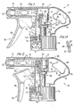
- a trigger actuated pump sprayer embodying the present invention is illustrated in Figures 1 and 2, generally designated 10, and comprises a pump body 11 of molded plastic construction having a cylindrical attaching portion 12 with an outwardly folded lower end 13 snap-fitted to a retainer 14 for coupling to a closure cap 15 to facilitate the mounting of the pump sprayer to the neck of a container of liquid to be sprayed.
- the coupling of the pump body to the closure cap forms no part of the invention, and is disclosed in commonly owned Spanish application No. 96 02671 filed on 18 December, 1996 and entitled "Dispenser".
- An integrally molded pump cylinder 16 of the pump body has a discharge port 17 opening into a discharge barrel 18 forming a discharge passage 19 having at its distal end a nozzle cap 21 containing a discharge orifice 22.
- a combined spinner/discharge valve assembly 23 having spring biasing means for the discharge valve is located in the discharge passage, and forms no part of the invention.
- a reciprocable piston assembly 24 includes a piston cup 25 having its piston seal 26 in fluid-tight sealing engagement with the inner wall of pump cylinder 16.
- Cup 25, as more clearly shown in Figure 3, has an inlet check valve in the form of a spider valve comprising a valve disc 27 mounted in place via resilient spider legs 28, as known in the art.
- Disc 27 seats against its valve seat 28 (Fig. 1) in all positions of the piston other than when undergoing its suction strokes.
- the piston assembly includes a piston stem 31 at the upper end of which the piston cup is frictionally mounted.
- the stem has a downwardly flaring container vent seal 32 in sliding sealing engagement with the inner wall of an upstanding sleeve 33 of retainer 14 for venting the interior of the container to atmosphere when vent seal 32 engages vent grooves 34 formed on the inner wall of sleeve 33, at or near the end of piston compression stroke shown in Figure 2.
- the piston stem further has a transversely extending annular flange 35 spaced a predetermined distance below piston seal 26.
- a trigger actuator 36 is mounted to the pump body as at 37 for pivotal movement between the Figure 1 and the Figure 2 positions upon a manual pull of trigger lever 38.
- the trigger actuator has a flat upper surface 39 adapted for engagement with the underside of discharge barrel 18 acting as a limit stop in the outward hinged direction of the trigger actuator of Figure 1.
- the pump body has a portion 41 at its rearward section which is ergonomically shaped for resting against the web of an operator's hand (not shown) during operation of the sprayer.
- Portion 41 is integrally molded with the pump body, and extends rearwardly from cylindrical attaching portion 12.
- the portion 41 forms a hand positioner which, when resting on the web of the operator's hand between the thumb and forefinger, supports the weight of the attached liquid filled container safely and conveniently on the top of the operator's hand.
- FIG. 1 Another portion of the rearward section of the pump body is open, i . e ., that portion between edges 42 and 43 at the rearward section of the pump body.
- This opening facilitates manufacture of the pump body, and the opening is conveniently closed by a hood 44 having male/female catches 45, 46 at opposite ends which cooperate with like female/male catches at edges 42, 43 of the pump body.
- Hood 44 provides a smooth continuation at the rear section to provide a smooth contour as shown.
- Hood 44 has affixed to its underside an external piston return spring assembly 47 which may comprise a pair of spaced bulbous spring legs 48 joined by a hub 49, and a leaf spring or spring arm 51 extending from hub 49 being essentially flat and unbent before assembly.
- Spring arm 51 has a forked end 52 defining a pair of spaced fingers which partially surround piston stem 31, and overlie top surface 53 of flange 35.
- the spaced fingers of forked end 52 has at the undersurface thereof a hemispherically shaped, transversely extending cam 54 presenting line contact against upper surface 53 of flange 35.
- the trigger actuator has a rearwardly extending arm 55 with a cammed edge 56 at its end in engagement with undersurface 57 of flange 35.
- spring arm 51 resiliently presses flange 35 against edge 56 of the trigger actuator whereby its upper surface 39 bears against the underside of the discharge barrel to limit the trigger actuator to its position shown in Figure 1.
- arm 55 pivots counterclockwise about mount 37 such that cam edge 56 shifts the piston assembly upwardly against the bias of spring assembly 47 whereupon the piston slides within the cylinder bore compressing the liquid therein which has been suctioned into pump chamber 20 during the previous suction stroke.
- the liquid is sprayed during each piston compression stroke out of orifice 22 as the pressurized liquid from the pump chamber opens the discharge valve of assembly 23, as in a manner known in the art.
- trigger actuator 36 is returned to its Figure 1 position by spring assembly 47 which simultaneously pulls the piston out, of its bore to thereby expand pump chamber 20 permitting liquid to be suctioned from the container (not shown) back into the pump chamber as in a manner know in the art.
- the hood with its attached piston spring assembly provides a smooth contoured profile for the rearward section of the low cost trigger sprayer while at the same time functions as an external dry spring which saves a part and thereby saves cost and which is easy to assemble.
- the fixed portion of the rearward section of the pump body functions as a hand positioner for the pump sprayer without the possibility of its unsnapping or unloosening during use as in some prior art designs.
Applications Claiming Priority (2)
| Application Number | Priority Date | Filing Date | Title |
|---|---|---|---|
| ES9700435 | 1997-02-28 | ||
| ES009700435A ES2154092B1 (es) | 1997-02-28 | 1997-02-28 | Pistola pulverizadora accionada por gatillo. |
Publications (2)
| Publication Number | Publication Date |
|---|---|
| EP0861692A2 true EP0861692A2 (fr) | 1998-09-02 |
| EP0861692A3 EP0861692A3 (fr) | 1999-04-07 |
Family
ID=8298449
Family Applications (1)
| Application Number | Title | Priority Date | Filing Date |
|---|---|---|---|
| EP97500072A Withdrawn EP0861692A3 (fr) | 1997-02-28 | 1997-04-23 | Pulvérisateur à pompe à gachette |
Country Status (3)
| Country | Link |
|---|---|
| US (1) | US5947341A (fr) |
| EP (1) | EP0861692A3 (fr) |
| ES (1) | ES2154092B1 (fr) |
Cited By (1)
| Publication number | Priority date | Publication date | Assignee | Title |
|---|---|---|---|---|
| EP1987887A1 (fr) * | 2007-05-03 | 2008-11-05 | Guala Dispensing S.P.A. | Tête d'un dispositif de distribution de fluide, dotée de moyens de retour élastiques |
Families Citing this family (11)
| Publication number | Priority date | Publication date | Assignee | Title |
|---|---|---|---|---|
| US6364172B1 (en) | 1998-12-10 | 2002-04-02 | Afa Polytek, B.V. | Liquid dispenser and assembly methods therefor |
| US6378739B1 (en) | 1999-03-05 | 2002-04-30 | Afa Polytek, B.V. | Precompression system for a liquid dispenser |
| DE10139573A1 (de) * | 2001-03-10 | 2002-09-19 | Alfred Von Schuckmann | Handhebel-betätigbare Pumpe |
| JP3916998B2 (ja) * | 2002-04-30 | 2007-05-23 | 株式会社吉野工業所 | トリガー式流体吐出器 |
| US8038040B2 (en) * | 2008-10-20 | 2011-10-18 | The Clorox Company | Bottle with integral dip tube |
| US20100096414A1 (en) * | 2008-10-20 | 2010-04-22 | Dennis Stephen R | Refillable Bottle Having Pour-Through Dispenser |
| JP4785152B2 (ja) * | 2008-12-09 | 2011-10-05 | キャニヨン株式会社 | トリガー式ポンプディスペンサー |
| IT1392636B1 (it) * | 2008-12-19 | 2012-03-16 | Guala Dispensing Spa | Sistema di collegamento anti-svitamento fra la testa di erogazione ed il contenitore di un dispositivo di erogazione di un liquido, ad esempio a grilletto |
| US20120280065A1 (en) * | 2011-03-24 | 2012-11-08 | Foster Donald D | Multi-chamber trigger sprayer |
| KR102289551B1 (ko) | 2019-07-17 | 2021-08-13 | 주식회사 제이투케이바이오 | 복합 히아루론산을 함유하는 화장료용 조성물 |
| US10875042B1 (en) * | 2019-09-20 | 2020-12-29 | O2Cool, Llc | Bottle closure |
Citations (4)
| Publication number | Priority date | Publication date | Assignee | Title |
|---|---|---|---|---|
| US4174069A (en) * | 1977-12-05 | 1979-11-13 | Diamond International Corporation | Adjustable spray fluid dispenser |
| US4815663A (en) * | 1977-03-02 | 1989-03-28 | Tetsuya Tada | Trigger type sprayer |
| US5356049A (en) * | 1993-03-29 | 1994-10-18 | Eastman Kodak Company | Hand pump assembly with a pump mechanism which is independent of the pump housing |
| EP0734783A2 (fr) * | 1992-10-21 | 1996-10-02 | Contico International, Incorporated | Pulvérisateur à gachette ayant une chambre de pompe à ressort interne à l'action duquel est soumis la piston de pompe |
Family Cites Families (5)
| Publication number | Priority date | Publication date | Assignee | Title |
|---|---|---|---|---|
| US4161288A (en) * | 1976-10-05 | 1979-07-17 | Creative Dispensing Systems, Inc. | Fluid dispenser method and apparatus |
| ES273524Y (es) * | 1983-07-14 | 1985-04-16 | Monturas Y Fornituras S.A. | Pistola proyectora de liquidos |
| US5425482A (en) * | 1990-10-25 | 1995-06-20 | Contico International, Inc. | Trigger sprayer |
| US5172836A (en) * | 1991-06-07 | 1992-12-22 | The Drackett Company | Ergonomic trigger sprayer and hand positioner therefor |
| IT1251196B (it) * | 1991-08-30 | 1995-05-04 | Coster Tecnologie Speciali Spa | Disposotivo spruzzatore perfezionato con leva a grilletto. |
-
1997
- 1997-02-28 ES ES009700435A patent/ES2154092B1/es not_active Expired - Lifetime
- 1997-04-23 EP EP97500072A patent/EP0861692A3/fr not_active Withdrawn
- 1997-07-15 US US08/892,651 patent/US5947341A/en not_active Expired - Fee Related
Patent Citations (4)
| Publication number | Priority date | Publication date | Assignee | Title |
|---|---|---|---|---|
| US4815663A (en) * | 1977-03-02 | 1989-03-28 | Tetsuya Tada | Trigger type sprayer |
| US4174069A (en) * | 1977-12-05 | 1979-11-13 | Diamond International Corporation | Adjustable spray fluid dispenser |
| EP0734783A2 (fr) * | 1992-10-21 | 1996-10-02 | Contico International, Incorporated | Pulvérisateur à gachette ayant une chambre de pompe à ressort interne à l'action duquel est soumis la piston de pompe |
| US5356049A (en) * | 1993-03-29 | 1994-10-18 | Eastman Kodak Company | Hand pump assembly with a pump mechanism which is independent of the pump housing |
Cited By (2)
| Publication number | Priority date | Publication date | Assignee | Title |
|---|---|---|---|---|
| EP1987887A1 (fr) * | 2007-05-03 | 2008-11-05 | Guala Dispensing S.P.A. | Tête d'un dispositif de distribution de fluide, dotée de moyens de retour élastiques |
| US7997455B2 (en) | 2007-05-03 | 2011-08-16 | Guala Dispensing S.P.A. | Head of a fluid dispensing device, provided with elastic return means |
Also Published As
| Publication number | Publication date |
|---|---|
| ES2154092A1 (es) | 2001-03-16 |
| EP0861692A3 (fr) | 1999-04-07 |
| US5947341A (en) | 1999-09-07 |
| ES2154092B1 (es) | 2001-10-16 |
Similar Documents
| Publication | Publication Date | Title |
|---|---|---|
| EP0850695B1 (fr) | Distributeur de produits liquides | |
| US4872596A (en) | Viscous product dispenser | |
| US5716008A (en) | Trigger sprayer | |
| US5947341A (en) | Trigger sprayer having rear hood supporting a return spring | |
| JPS6028529Y2 (ja) | 蓄圧タイプの噴霧器 | |
| US4033487A (en) | Double trigger pump | |
| US4249681A (en) | Leak-proof sprayer | |
| US5353969A (en) | Invertible pump sprayer having spiral vent path | |
| US4944431A (en) | Trigger sprayer with multi-function piston | |
| US5242089A (en) | Miniature pump sprayer | |
| WO1989000137A1 (fr) | Pompe a poignee de commande | |
| EP1137493B1 (fr) | Systeme de precompression | |
| US4494680A (en) | Manually operated dispensing pump | |
| AU2004201921B2 (en) | Low cost, in-line trigger operated pump sprayer | |
| US5762236A (en) | Trigger mechanism for trigger sprayer | |
| US11135607B2 (en) | Trigger pump dispenser | |
| JPS6346144Y2 (fr) | ||
| CA2466236A1 (fr) | Atomiseur a detente en ligne de cout modique | |
| NZ532813A (en) | Low-cost, in-line trigger operated pump sprayer |
Legal Events
| Date | Code | Title | Description |
|---|---|---|---|
| PUAI | Public reference made under article 153(3) epc to a published international application that has entered the european phase |
Free format text: ORIGINAL CODE: 0009012 |
|
| AK | Designated contracting states |
Kind code of ref document: A2 Designated state(s): BE DE ES FR GB IT NL SE |
|
| AX | Request for extension of the european patent |
Free format text: AL;LT;LV;RO;SI |
|
| PUAL | Search report despatched |
Free format text: ORIGINAL CODE: 0009013 |
|
| AK | Designated contracting states |
Kind code of ref document: A3 Designated state(s): AT BE CH DE DK ES FR GB GR IE IT LI LU MC NL PT SE |
|
| AX | Request for extension of the european patent |
Free format text: AL;LT;LV;RO;SI |
|
| 17P | Request for examination filed |
Effective date: 19990423 |
|
| AKX | Designation fees paid |
Free format text: BE DE ES FR GB IT NL SE |
|
| 17Q | First examination report despatched |
Effective date: 20010525 |
|
| STAA | Information on the status of an ep patent application or granted ep patent |
Free format text: STATUS: THE APPLICATION IS DEEMED TO BE WITHDRAWN |
|
| 18D | Application deemed to be withdrawn |
Effective date: 20011005 |