EP0861373B1 - Thermochemische, mechanische betätigungsvorrichtung mit proportionalsteuerung - Google Patents
Thermochemische, mechanische betätigungsvorrichtung mit proportionalsteuerung Download PDFInfo
- Publication number
- EP0861373B1 EP0861373B1 EP96942002A EP96942002A EP0861373B1 EP 0861373 B1 EP0861373 B1 EP 0861373B1 EP 96942002 A EP96942002 A EP 96942002A EP 96942002 A EP96942002 A EP 96942002A EP 0861373 B1 EP0861373 B1 EP 0861373B1
- Authority
- EP
- European Patent Office
- Prior art keywords
- circuit
- signal
- feedback
- thermal actuator
- heating element
- Prior art date
- Legal status (The legal status is an assumption and is not a legal conclusion. Google has not performed a legal analysis and makes no representation as to the accuracy of the status listed.)
- Expired - Lifetime
Links
- 239000000463 material Substances 0.000 claims description 43
- 238000010438 heat treatment Methods 0.000 claims description 34
- 229920000642 polymer Polymers 0.000 claims description 31
- 239000007788 liquid Substances 0.000 claims description 16
- 230000008859 change Effects 0.000 claims description 13
- 238000000034 method Methods 0.000 claims description 11
- 239000007787 solid Substances 0.000 claims description 4
- 239000012782 phase change material Substances 0.000 claims description 2
- 230000011664 signaling Effects 0.000 claims 1
- 239000012071 phase Substances 0.000 description 6
- 230000008901 benefit Effects 0.000 description 5
- 238000002485 combustion reaction Methods 0.000 description 4
- 230000004907 flux Effects 0.000 description 4
- 239000013307 optical fiber Substances 0.000 description 4
- 230000004044 response Effects 0.000 description 4
- 238000012546 transfer Methods 0.000 description 4
- 239000004698 Polyethylene Substances 0.000 description 3
- 239000003990 capacitor Substances 0.000 description 3
- 238000001816 cooling Methods 0.000 description 3
- 239000000155 melt Substances 0.000 description 3
- 230000003287 optical effect Effects 0.000 description 3
- -1 polyethylene Polymers 0.000 description 3
- 229920000573 polyethylene Polymers 0.000 description 3
- 238000006243 chemical reaction Methods 0.000 description 2
- 238000004891 communication Methods 0.000 description 2
- 238000001739 density measurement Methods 0.000 description 2
- 230000001419 dependent effect Effects 0.000 description 2
- 230000000694 effects Effects 0.000 description 2
- 239000012530 fluid Substances 0.000 description 2
- 239000000203 mixture Substances 0.000 description 2
- 229910001120 nichrome Inorganic materials 0.000 description 2
- 230000010355 oscillation Effects 0.000 description 2
- 239000012188 paraffin wax Substances 0.000 description 2
- 239000012808 vapor phase Substances 0.000 description 2
- XLYOFNOQVPJJNP-UHFFFAOYSA-N water Substances O XLYOFNOQVPJJNP-UHFFFAOYSA-N 0.000 description 2
- XAGFODPZIPBFFR-UHFFFAOYSA-N aluminium Chemical compound [Al] XAGFODPZIPBFFR-UHFFFAOYSA-N 0.000 description 1
- 229910052782 aluminium Inorganic materials 0.000 description 1
- 230000003321 amplification Effects 0.000 description 1
- 238000013459 approach Methods 0.000 description 1
- 238000009835 boiling Methods 0.000 description 1
- 239000004020 conductor Substances 0.000 description 1
- 230000008602 contraction Effects 0.000 description 1
- 230000007423 decrease Effects 0.000 description 1
- 238000010586 diagram Methods 0.000 description 1
- 238000006073 displacement reaction Methods 0.000 description 1
- 239000000835 fiber Substances 0.000 description 1
- 230000004927 fusion Effects 0.000 description 1
- 229930195733 hydrocarbon Natural products 0.000 description 1
- 150000002430 hydrocarbons Chemical class 0.000 description 1
- 230000010354 integration Effects 0.000 description 1
- 238000002955 isolation Methods 0.000 description 1
- 239000007791 liquid phase Substances 0.000 description 1
- 238000005259 measurement Methods 0.000 description 1
- 238000002844 melting Methods 0.000 description 1
- 230000008018 melting Effects 0.000 description 1
- 238000003199 nucleic acid amplification method Methods 0.000 description 1
- 239000004033 plastic Substances 0.000 description 1
- 229920003023 plastic Polymers 0.000 description 1
- 230000008569 process Effects 0.000 description 1
- 230000035939 shock Effects 0.000 description 1
- 238000009834 vaporization Methods 0.000 description 1
- 230000008016 vaporization Effects 0.000 description 1
- 239000001993 wax Substances 0.000 description 1
Images


Classifications
-
- F—MECHANICAL ENGINEERING; LIGHTING; HEATING; WEAPONS; BLASTING
- F03—MACHINES OR ENGINES FOR LIQUIDS; WIND, SPRING, OR WEIGHT MOTORS; PRODUCING MECHANICAL POWER OR A REACTIVE PROPULSIVE THRUST, NOT OTHERWISE PROVIDED FOR
- F03G—SPRING, WEIGHT, INERTIA OR LIKE MOTORS; MECHANICAL-POWER PRODUCING DEVICES OR MECHANISMS, NOT OTHERWISE PROVIDED FOR OR USING ENERGY SOURCES NOT OTHERWISE PROVIDED FOR
- F03G7/00—Mechanical-power-producing mechanisms, not otherwise provided for or using energy sources not otherwise provided for
- F03G7/06—Mechanical-power-producing mechanisms, not otherwise provided for or using energy sources not otherwise provided for using expansion or contraction of bodies due to heating, cooling, moistening, drying or the like
- F03G7/061—Mechanical-power-producing mechanisms, not otherwise provided for or using energy sources not otherwise provided for using expansion or contraction of bodies due to heating, cooling, moistening, drying or the like characterised by the actuating element
- F03G7/06112—Mechanical-power-producing mechanisms, not otherwise provided for or using energy sources not otherwise provided for using expansion or contraction of bodies due to heating, cooling, moistening, drying or the like characterised by the actuating element using the thermal expansion or contraction of enclosed fluids
- F03G7/06113—Mechanical-power-producing mechanisms, not otherwise provided for or using energy sources not otherwise provided for using expansion or contraction of bodies due to heating, cooling, moistening, drying or the like characterised by the actuating element using the thermal expansion or contraction of enclosed fluids the fluids subjected to phase change
-
- F—MECHANICAL ENGINEERING; LIGHTING; HEATING; WEAPONS; BLASTING
- F03—MACHINES OR ENGINES FOR LIQUIDS; WIND, SPRING, OR WEIGHT MOTORS; PRODUCING MECHANICAL POWER OR A REACTIVE PROPULSIVE THRUST, NOT OTHERWISE PROVIDED FOR
- F03G—SPRING, WEIGHT, INERTIA OR LIKE MOTORS; MECHANICAL-POWER PRODUCING DEVICES OR MECHANISMS, NOT OTHERWISE PROVIDED FOR OR USING ENERGY SOURCES NOT OTHERWISE PROVIDED FOR
- F03G7/00—Mechanical-power-producing mechanisms, not otherwise provided for or using energy sources not otherwise provided for
- F03G7/06—Mechanical-power-producing mechanisms, not otherwise provided for or using energy sources not otherwise provided for using expansion or contraction of bodies due to heating, cooling, moistening, drying or the like
- F03G7/066—Actuator control or monitoring
-
- G—PHYSICS
- G05—CONTROLLING; REGULATING
- G05D—SYSTEMS FOR CONTROLLING OR REGULATING NON-ELECTRIC VARIABLES
- G05D23/00—Control of temperature
- G05D23/19—Control of temperature characterised by the use of electric means
- G05D23/1919—Control of temperature characterised by the use of electric means characterised by the type of controller
- G05D23/1921—Control of temperature characterised by the use of electric means characterised by the type of controller using a thermal motor
Definitions
- the present invention relates to mechanical power supplies and actuators. It finds particular application in conjunction with high force, low travel extensible actuators and will be described with particular reference thereto. However, it is to be appreciated that the invention will also find application in conjunction with other high pressure fluid systems, as well as other mechanical power supplies, pumps, motors, pressure cylinders, valve controllers, and the like.
- One way to effect heat transfer is by physically moving mass, e.g., moving a liquid to a heat source. Heated liquid/vapor is caused to flow against resistance to a cooling source. Steam and other types of external combustion engines typify this technique.
- heat energy locked in molecular bonding is pumped into a combustion chamber. The mix is ignited and the combustion vapor is permitted to exit the chamber against resistance, physically removing the heat and clearing the chamber for the next cycle.
- the internal combustion engine typifies this mode.
- liquid/vapor phase techniques have several drawbacks.
- heat Rather than transporting the material which is acted upon by the heat to expand and contract, the heat itself may be moved. More specifically, as shown in U.S. Patent Nos. 5,177,969 and 5,025,627, heat can be conducted into and out of a sealed chamber which expands during the heating cycle and contracts during the cooling cycle.
- the sealed chamber technique has many advantages including its mechanical simplicity, high stiffness actuation, ready adaption to a variety of heat sources, high power density, and silent operation. Moreover, because liquids compress only a small amount, as compared to vapors, they tend to be much safer than a liquid/vapor system. Unfortunately, the transfer of heat into and out of the medium normally relies on thermal conductivity. Mediums which exhibit good expansion/ contraction ratios upon melting tend to have relatively poor thermal conductivities. Thus, a solid/liquid sealed chamber phase change actuator tends to have a very slow cycle time.
- the sealed chamber devices have been controllable to selected throws or degrees of extension.
- the actuator is cycled extending until a first limit switch is tripped, stopping actuation power.
- the unit retracts and contacts a second limit switch, power is again supplied.
- the document US.4.451 793 shows a feedback control system in which the error signal is oscillated by a dither signal having a periodical pattern for oscillating the controlled output.
- the present invention contemplates a new and improved proportional control for sealed chamber actuators.
- an electrically controlled thermal actuator system is provided.
- An actuator body defines an interior chamber containing a material that expands when heated.
- An extension member is connected with the material to extend relative to the actuator body as a material is heated.
- a power supply selectively supplies electrical power to a heating element that is disposed in the interior chamber.
- An input circuit provides a control signal indicative of a selected degree of extension of the extension member relative to the thermal actuator body.
- a feedback circuit senses a condition of the thermal actuator and provides a feedback signal indicative of the sensed condition.
- An error signal determines a deviation between the control signal and the feedback signal and controls the power supply in accordance therewith.
- a dither circuit generates an oscillating dither signal.
- the dither circuit is connected with one of the input circuit, the feedback circuit, and the error circuit for adding the dither signal to one of the control and feedback signals.
- the feedback circuit senses at least one of position, speed, or force of the extension member.
- the feedback circuit senses parameters which are indicative of at least one of temperature, pressure, and specific volume and quantity of the material, integrated power input into the heating element, a dielectric constant of the material, resistivity of the material, translucency of the material, and pressure in the material.
- the material is a phase change material which changes with heat between (i) crystalline states, (ii) solid and liquid states, or (iii) liquid and gaseous states.
- a method of controlling a thermal actuator includes an actuator body defining an interior chamber that contains a material which expands when heated.
- An expansion member is connected with the material to extend relative to the body portion as the material is heated.
- a heating element is disposed in the interior chamber.
- a condition of the thermal actuator is sensed and a corresponding feedback signal is generated.
- a reference signal is provided which is indicative of a selected degree of extension or force of extension of the extension member relative to the thermal actuator body.
- the reference and feedback signals are compared to produce an error signal indicative of a deviation therebetween.
- An amount of power supplied to the heating element is adjusted in accordance with the error signal.
- an oscillating dither component is added to one of the control and feedback signals.
- One advantage of the present invention resides in its ability to produce true and accurate proportional control.
- Another advantage of the present invention resides in its mechanical simplicity.
- Still other advantages of the present invention include high power densities, silent operation, safety, rapid operating speeds, and high stiffness.
- the invention may take form in various components and arrangements of components, and in various steps and arrangements of steps.
- the drawings are only for purposes of illustrating a preferred embodiment and are not to be construed as limiting the invention.
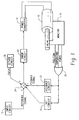
- an operator or reference input circuit 10 provides an input signal indicative of a desired position, speed, actuation force, temperature of the control device, or the like.
- An error circuit 12 determines an error between the reference input and a corresponding feedback signal to generate an error signal.
- Suitable error circuits include differential amplifiers, comparators, and microprocessors.
- a power conversion device 14 converts the error signal into an appropriate electrical power level for a sealed chamber thermal actuator 16 , such as the actuators shown in U.S. Patent Nos. 5,025,627, 5,177,969, 5,419,133, or pending U.S. Patent Application Serial No. 08/447,914.
- a feedback monitor 18 monitors selected responses of the thermal actuator 16 .
- the monitored response(s) corresponds to the reference input from the reference input circuit 10 .
- the monitored physical conditions include position, change in position or speed, force, temperature, pressure, optical transparency (of the polymer), quality, and the like.
- an OR circuit 20 When there are more than one feedback monitor which may be selected, an OR circuit 20 combines or passes the selected one as a feedback signal.
- a feedback signal circuit 22 provides any appropriate adjustment to the magnitude, amplification, or other characteristics of the feedback signal such that its magnitude and other characteristics correspond to the reference input from the input circuit 10 .
- the reference input circuit and the feedback signal are compared by being applied to positive and negative inputs of a differential amplifier, subtracted at a summing junction 24 , or the like.
- a limit control circuit 26 monitors for limit conditions such as a limit extension, maximum or limit temperature, maximum or limit force, or the like. In response to this limit being reached, the limit control circuit provides a signal to the error circuit which causes it to zero or reduce the error signal, hence stops or reduces the amount of power supplied by the power converter 14 .
- a dither circuit 30 provides an oscillating dither signal which is summed with the reference (or feedback) signal.
- the dither signal has a frequency which is commensurate with a speed of the thermal actuator. With the thermal actuator of the preferred embodiment that has an actuation time of about 1.5 seconds, a dither frequency of about 10 to 50 hertz is provided, with about 20 hertz being preferred.
- the dither signal has an amplitude which is a fraction of the reference (or feedback) signal.
- the dither circuit can be interconnected with the reference input such that the dither amplitude is adjusted in accordance with the amplitude of the reference input, e.g., 10% of the reference signal. Alternately, the dither signal can have an amplitude that is a fixed fraction.
- the limit control 10 in the preferred embodiment compares a variable DC voltage source to a fixed value. It includes an operational amplifier 40 configured as a comparator to limit the input to the fixed value.
- the error signal circuit 12 includes a differential amplifier 44 that receives the control signal in one of its positive and negative inputs, the positive input in the preferred embodiment.
- the power converter includes a light emitting diode or other optical source 46 coupled with a light sensitive triac 48 or the like to provide electric isolation between the error signal and the thermal actuator 16 .
- a light sensitive triac 48 or the like to provide electric isolation between the error signal and the thermal actuator 16 .
- magnetic, radio frequency, and other interconnections which do not provide a direct electrical connection may also be utilized.
- direct electrical connections can be utilized and may be advantageous for circuit simplicity and efficiency.
- the light sensitive device 48 is connected with a triac 50 which controls the percentage of each oscillation of an AC power source 52 which is supplied to a heating coil 54 of the thermal actuator 16 .
- a MOSFET transistor, or the like replaces the triac 50 .
- the thermal actuator includes first and second body portions 56, 58 which define an interior chamber 60 .
- the body portions 56 and 58 have conical, cylindrical, or other geometry surfaces which are parallel and closely adjacent to each other such that the interior chamber 60 is a thin, disk, conical or tubular region.
- the heating element 54 is wound in a helical pattern through the conical sealed chamber 60 , extending between high pressure electrical feedthroughs 62, 64 .
- An extensible member 66 such as a pin, snap dome, bellows, or the like is connected with the sealed chamber 60 .
- the chamber is filled with a material which expands as it is heated, extending the extensible element 66 and contracts as it cools, allowing the extensible element to be retracted.
- the material undergoes a phase change which provides an effective conversion of thermal energy into expansive force.
- Suitable phase changes include changes between crystalline states, between solid and liquid states, and between liquid and gaseous states.
- Suitable material include paraffin wax, synthetic waxes, freon, and other hydrocarbons.
- the heating element 54 is nichrome wire that is mounted on electrically insulating offset members, such as plastic ribs 68 , which holds the nichrome wires in a spaced relationship relative to the body portions 56, 58 .
- the body members are made of a highly thermally conductive material, such as aluminum, which is also electrically conductive.
- the electrical resistance wire are mounted within only a few polymer molecular lengths of each other and the walls of the body members.
- the heating wires are spaced within 0.3 cm apart, preferably 0.1 cm apart or less. The heating wires are also spaced a similar dimension from the walls.
- the polymer is preferably a medium chain polyethylene, such as paraffin.
- medium chain polyethylenes each have a temperature at which they undergo a phase change. A selection is made among the various polyethylenes in accordance with the temperature of the environment in which the thermal actuator is to be operated.
- the monitor circuit 18 of the illustrated embodiment monitors extension of the extensible member 66 .
- the extensible member is connected with a slide member 70 of a potentiometer 72 .
- a reference voltage 74 is applied across the variable resistor such that the signal output on the slide 70 is proportional to extension of the extensible member and of a magnitude and range which matches the magnitude and range of the control signal from the input circuit 10 .
- the feedback signal is connected to the negative input of the differential amplifier 44 such that the error signal is the difference between the control or reference signal and the feedback signal.
- the feedback circuit 22 has an amplifier 76 that provides an adjustable reference voltage for the opposite end of the potentiometer.
- An adjustable reference voltage 78 provides a zero adjustment for the output of the potentiometer 72 .
- Adjusting the reference voltage 74 at the other end of the potentiometer provides an adjustment for the voltage range or span of the feedback signal.
- a linear transformer, optical sensors, magnetic sensors, and the like can be used to measure extension.
- a differentiating circuit may be provided to differentiate the position and provide an indication of the speed of extension.
- a thermocouple can be embedded in the polymeric material in the sealed chamber 60 or very closely thereto to sense temperature of the polymer.
- a current sensor can be connected with one of the feedthroughs 62 to determine the temperature of the heating element 54 based on the electrical current drawn, resistance across the heating element, or other electrical characteristics.
- the limit control 26 provides a limit signal which causes the error circuit to stop the thermal actuator from extending further or otherwise exceeding temperature limits of the actuator.
- the limit control circuit 26 senses temperature of the thermal element or the polymer. A limit signal is provided when preselected temperature limits are exceeded.
- An amplifier 80 is connected with a thermocouple 82 . When the temperature exceeds a preselected limit, the reference or control signal is reduced or even zeroed.
- the dither circuit 30 of the preferred embodiment includes an oscillator which provides an oscillating output. With the preferred thermal device that has an actuation speed of about 1.5 seconds, an oscillation frequency of about 20 hertz is preferred.
- the oscillator of the preferred embodiment includes an amplifier 90 having one input connected with a capacitor 92 and the other input connected in a feedback loop. The feedback loop is interconnected with the control circuit 10 to control the amplitude in accordance with the amplitude of the control signal.
- the dither signal is controlled to have an amplitude of about 10% of the input signal.
- the width of its pulses can be modulated, or the like. The dither overcomes errors due to pin friction or stick slip.
- a positive temperature coefficient (PTC) thermistor device 94 is mounted in thermal communication with the polymer.
- the PTC device is connected between the power converter 14 and the heating element 54. As the PTC device warms, its electrical resistance increases, reducing the amount of electrical power supplied to the heating element.
- the PTC device is amenable to open loop control systems.
- the open loop control system includes a power supply which supplies power for the heating coil.
- a power level control such as a pulse width modulator, adjusts the amount of power delivered to the heating coil.
- the preferred pulse width modulator has a constant voltage amplitude, but has pulses of variable width to adjust the amount of energy supplied to the heating coil.
- other power supplies are contemplated such as adjustable magnitude voltage supplies, and the like.
- a positive temperature coefficient (PTC) thermistor device is connected between the power supply and the filament.
- the PTC thermistor is mounted closely adjacent the polymeric material in close thermal communication. Because the positive temperature coefficient device has an electrical resistance that increases with temperature, as the temperature of the polymer approaches a limit temperature, the amount of current passed to the heating element decreases. Eventually a steady-state maximum temperature is reached.
- a plurality of PTC devices 94 1 , 94 2 , 94 3 , ..., are positioned around the interior chamber 60.
- Each PTC device is selected to have different temperature characteristics.
- the response curve can be adjustably selected.
- a diode 96 is connected in series with one or more of the PTC devices to provide for dead heading. For example, a relatively sharp cut-off can be achieved such that extension is proportional to power to a preselected set point after which added power causes substantially no more heating.
- Other combinations of PTC devices can be used to make the power to extension curve follow preselected linear or non-linear characteristics.
- a linear voltage displacement transducer can be utilized to measure the position of the extensible member 66 .
- Load cells may be used to measure force of the extensible element.
- LVDTs and load cells tend to be relatively expensive.
- the sealed chamber thermal actuator 16 uses polymers which expand or change volume to create pressure which powers the actuator.
- the thermal state of the polymer is a thermodynamic property which can typically be described uniquely by temperature, pressure, and specific volume of the material.
- the polymer pressure is directly related to the force or load of the actuator; and the specific volume of the polymer is directly related to the extension of the actuator.
- knowing any two of the temperature, pressure, and specific volume parameters enables the third to be calculated.
- a discontinuity occurs in which the temperature and pressure parameters are no longer independent. Rather, these two parameters become dependent such that an additional parameter is needed to characterize the system uniquely.
- thermocouple 82 of FIGURE 2 rather than being a limit condition sensor, can be utilized to sense the temperature parameter. Although there may be temperature variations across the interior chamber of the actuator, appropriate calibration of the electronic circuitry is sufficient such that the temperature signal can be utilized as the feedback signal.
- the quality parameter of the system can be determined by a specific volume measurement of the polymer or by a density measurement. Specific volume, again, is determinable by extension of the extensible member, but may also be determined by integrating the total heat input into the system, or by density measurements, for a system with known enthalpy and entropy states.
- the heat input can be measured and integrated by a circuit 100 connected with the input leads 62, 64 , of the actuator 16 .
- the heat input integration can be determined by calculating the total number of heating watts supplied, less the heat flux which flows from the actuator to a heat sink. If the heat flux to the heat sink is constant, the heat calibration of the circuit 100 can remove its effect. If the heat sink temperature varies, then the heat flux will be a function of the sink temperature. By measuring the temperature of the heat sink, a calculation of the heat flux to the sink can be calculated, integrated, and subtracted from the input wattage.
- the feedback monitor 18 measures the density of the polymer directly which a circuit 102 converts to an indication of the specific volume.
- Various techniques can be utilized for measuring the density of the polymer.
- the embodiment of FIGURE 5 uses a property found in many polymers in that they change from a translucent to a clear color as they melt.
- An LED 104 provides light which is carried by an optical fiber 106 into the polymer in the sealed chamber 60 .
- a second optical fiber 108 has an end spaced from the first optical fiber 106 by a gap which is filled by the polymer.
- Photodiodes 110 and 112 measure the intensity of light transmitted into the polymer and the amount of light which crossed through the polymer in the gap.
- a ratio circuit 114 determines a ratio of these intensities provides an indication of the translucency or clarity of the polymer, hence its density and specific volume.
- a specific volume circuit 116 converts the ratio into a signal indicative of specific volume. The exact details of the specific volume circuit are dependent on the polymer selected. Alternately, an index of refraction type of fiber optic sensor can be used to sense a melt state of the polymer.
- a pressure sensor 118 is placed in the sealed chamber 60 .
- Various pressure sensors are contemplated such as an optical fiber pressure sensor, a capacitive pressure sensor, or the like.
- a pressure output circuit 120 provides a signal that is proportional to pressure.
- a circuit 122 converts the pressure and specific volume to provide a direct indication of extension and force of the actuator.
- the error circuit 12 preferably a computer, compares actual extension and force characteristics with the operating characteristics input by the input circuit 10 and controls the power supply 14 accordingly.
- the functions of circuit 122 and 12 are incorporated into a common microprocessor.
- the quality of the polymer can also be determined from its electrical properties.
- the feedback monitor includes a circuit 130 which measures the capacitance or the resistance between the heating coil 54 and the body of the actuator. It is to be appreciated that the heating coil and the body are separated from each other by the dielectric polymer to define a capacitor. As the dielectric properties of the polymer change with temperature, the capacitance of the capacitor changes. Analogously, the polymer is part of a resistive path between the heating coil and the body of the polymer. Changes in density again cause a change in resistance which is again indicative of the quality parameter. Analogously, independent sensors or sensing elements may be positioned in the sealed chamber 60 in contact with the polymer to sense the changes in its dielectric properties electrically.
- the circuit 130 also reads the resistance across the leads 62, 64 to provide an indication of temperature. From the temperature and quality of the polymer, the force and extension of the extensible member are readily calculated by a circuit 132. The force and extension of the extensible member from circuit 132 is compared with a desired extension or force input by input 10 by a central controller 12 , preferably computer-based.
Landscapes
- Engineering & Computer Science (AREA)
- Chemical & Material Sciences (AREA)
- Combustion & Propulsion (AREA)
- Mechanical Engineering (AREA)
- General Engineering & Computer Science (AREA)
- Physics & Mathematics (AREA)
- General Physics & Mathematics (AREA)
- Automation & Control Theory (AREA)
- Control Of Temperature (AREA)
Claims (10)
- Elektrisch gesteuerte, thermische Betätigungsvorrichtung, umfassend ein Stellgliedgehäuse (56, 58), das eine innere Kammer (60) bildet, die ein Material enthält, das sich bei Erwärmung ausdehnt, ein mit dem Material verbundenes Verlängerungsteil (66), das relativ zu dem Stellgliedgehäuse ausfährt, wenn das Material erwärmt wird, ein in der inneren Kammer angeordnetes Heizelement (54), und eine Stromversorgung (52), um dem Heizelement selektiv elektrische Energie zuzuführen,gekennzeichnet durcheine Eingangsschaltung (10), um ein Steuersignal zu erzeugen, das auf einen gewählten Grad von Verlängerung oder Kraft des Verlängerungsteils relativ zu dem Gehäuse des thermischen Stellglieds schließen läßt;eine Rückkopplungsschaltung (18, 22, 26, 130), die (1) einen Zustand des thermischen Stellglieds efaßt und (2) ein Rückführungssignal liefert, das auf den erfaßten Zustand schließen läßt;eine Fehlerschaltung (12) zum Bestimmen einer Abweichung zwischen dem Steuersignal und dem Rückführungssignal und zum Steuern der Stromversorgung in Übereinstimmung damit;
eine Zittersignal-Schaltung (30) zum Erzeugen eines oszillierenden Zittersignals, Wobei die Zittersignal-Schaltung mit einer der Schaltungen: Eingangsschaltung (10), Rückkopplungsschaltung (18, 22, 26, 130), Fehlerschaltung (12) verbunden ist, um das Zittersignal zu erinem der Signale:Steuersignal und Rückführungssignal zu addieren. - Thermische Betätigungsvorrichtung nach Anspruch 1, weiter gekennzeichnet dadurch:
dass das Material eine isothermische Phasenumwandlung durchmacht, wenn es sich ausdehnt. - Thermische Betätigungsvorrichtung nach Anspruch 2, weiter dadurch gekennzeichnet:
dass eine der Schaltungen Eingangsschaltung und Rückkopplungsschaltung (10, 18, 22, 26, 130) mit der Zittersignal-Schaltung (12) verbunden ist, um eine Amplitude des Zittersignals entsprechend einer Amplitude von mindestens einem der Signale Steuersignal und Rückführungssignal zu steuern. - Thermische Betätigungsvorrichtung nach einem der vorhergehenden Ansprüche, weiter gekennzeichnet durch:
die Rückkopplungsschaltung (18, 22, 26) mit einem Sensor (18), der mit dem Verlängerungsteil (66) verbunden ist, um ein elektrisches Signal zu erzeugen, das sich zumindest entsprechend einem der Werte Ausdehnung, Geschwindigkeit, Kraft des Verlängerungsteils ändert. - Thermische Betätigungsvorrichtung nach einem der vorhergehenden Ansprüche, weiter gekennzeichnet durch die Rückkopplungsschaltung, die Parameter erkennt, die zumindest auf eines von:Temperatur, Druck, und spezifischem Volumen und Qualität des Materials;integrierter Leistungsaufnahme in dem Heizelement;eine Dielektrizitätskonstante des Materials;Widerstandsfähigkeit des Materials;Licht-Durchlässigkeit des Materials; undDruck in dem Materialschließen lassen.
- Thermische Betätigungsvorrichtung nach einem der vorhergehenden Ansprüche, weiter gekennzeichnet durch:
einen mit der Stromversorgung elektrisch verbundenen Thermistor (94) mit positivem Temperaturkoeffizient und zumindest einem von beiden, Heizelement oder Heizelement-Stromfühler verbunden ist. - Thermische Betätigungsvorrichtung nach einem der vorhergehenden Ansprüche, weiter dadurch gekennzeichnet:
dass das Material ein Phasenumwandlungsmaterial ist, das sich bei Wärme umwandelt zwischen (i) kristallinen Zuständen, (ii) festen und flüssigen Zuständen, oder (iii) flüssigen und gasförmigen Zuständen. - Verfahren zur Steuerung eines thermischen Stellglieds (16), das ein Stellgliedgehäuse (56, 58) umfaßt, das eine innere Kammer (60) bildet, die ein Material enthält, das sich bei Erwärmung ausdehnt, ein mit dem Material verbundenes Verlängerungsteil (66), das relativ zu dem Stellgliedgehäuse ausfährt, wenn das Material erwärmt wird, und ein in der inneren Kammer angeordnetes Heizelement (54), welches einschließt:Erfassen (18) eines Zustandes des thermischen Stellglieds (16) und Erzeugen eines Rückführungssignals entsprechend dem erfaßten Zustand;Bereitstellen (10) eines Bezugssignals, das auf einen ausgewählten Grad der Ausdehnung oder Kraftzunahme des Verlängerungsteils relativ zu dem Gehäuseteil schließen läßt, gekennzeichnet durch Addieren (30) einer oszillierenden Zittersignal-Komponente zu mindestens einem der Signale Steuersignal und Rückführungssignal;Vergleichen (24) der Bezugssignale und der Rückführungssignale, um ein Fehlersignal (12) zu erzeugen, das auf eine Abweichung zwischen diesen schließen läßt;Einstellen (14) einer in das Heizelement entsprechend dem Fehlersignal zugeführten Energiemenge.
- Verfahren nach Anspruch 8, weiter gekennzeichnet durch:
Hinzugeben von Wärme zu dem Material, derart, dass es eine isothermische Phasenumwandlung durchmacht, wobei sich das Material während einer Phasenumwandlung ausdehnt und seine Temperatur konstant bleibt. - Verfahren gemäß einem der Ansprüche 8 oder 9, weiter dadurch gekennzeichnet, dass der erfaßte Zustand mindestens einen der folgenden Zustände umfaßt:Stellung des Verlängerungsteils;Geschwindigkeit des Verlängerungsteils;Kraft des Verlängerungsteils;integrierte Leistungsaufnahme in dem Heizelement;eine Dielektrizitätskonstante des Materials;Widerstandsfähigkeit des Materials;Lichtdurchlässigkeit des Polymers; undDruck des Materials.
Applications Claiming Priority (3)
| Application Number | Priority Date | Filing Date | Title |
|---|---|---|---|
| US08/557,278 US5685149A (en) | 1995-11-14 | 1995-11-14 | Proportionally controlled thermochemical mechanical actuator |
| US557278 | 1995-11-14 | ||
| PCT/US1996/018326 WO1997018393A1 (en) | 1995-11-14 | 1996-11-08 | Proportionally controlled thermochemical mechanical actuator |
Publications (2)
| Publication Number | Publication Date |
|---|---|
| EP0861373A1 EP0861373A1 (de) | 1998-09-02 |
| EP0861373B1 true EP0861373B1 (de) | 2000-08-30 |
Family
ID=24224761
Family Applications (1)
| Application Number | Title | Priority Date | Filing Date |
|---|---|---|---|
| EP96942002A Expired - Lifetime EP0861373B1 (de) | 1995-11-14 | 1996-11-08 | Thermochemische, mechanische betätigungsvorrichtung mit proportionalsteuerung |
Country Status (4)
| Country | Link |
|---|---|
| US (1) | US5685149A (de) |
| EP (1) | EP0861373B1 (de) |
| DE (1) | DE69610115T2 (de) |
| WO (1) | WO1997018393A1 (de) |
Cited By (3)
| Publication number | Priority date | Publication date | Assignee | Title |
|---|---|---|---|---|
| DE10356930B4 (de) * | 2003-12-05 | 2009-03-05 | Preh Gmbh | Ansteuerung für Stellmotoren |
| US11224777B2 (en) | 2019-02-25 | 2022-01-18 | Honeywell International Inc. | Fire and smoke actuator with temperature-dependent operating speed |
| WO2025041701A1 (en) * | 2023-08-18 | 2025-02-27 | Murata Manufacturing Co., Ltd. | Ac pulse control of pcm switch |
Families Citing this family (30)
| Publication number | Priority date | Publication date | Assignee | Title |
|---|---|---|---|---|
| SE9503286L (sv) * | 1995-09-22 | 1997-03-17 | Alfa Laval Automation Ab | Förfarande samt reglersystem för friktionskomepensation |
| US5822989A (en) * | 1996-06-03 | 1998-10-20 | Tcam Technologies, Inc. | Thermochemical/mechanical brake and clutch unit |
| GB9815724D0 (en) * | 1998-07-21 | 1998-09-16 | Rigibore Ltd | Actuator and positioning device |
| US6192684B1 (en) | 1999-03-18 | 2001-02-27 | Swales Aerospace | Mechanical actuator assembly |
| US6481204B1 (en) | 2001-07-02 | 2002-11-19 | Tcam Power Workholding, Llc | Expansible polymer clamping device |
| SE0200409D0 (sv) | 2002-02-13 | 2002-02-13 | Siemens Elema Ab | Method of Controlling a Valve Element and Valve Assembly |
| US6880942B2 (en) * | 2002-06-20 | 2005-04-19 | Nikon Corporation | Adaptive optic with discrete actuators for continuous deformation of a deformable mirror system |
| JP2006526131A (ja) | 2003-04-28 | 2006-11-16 | ナノマッスル・インコーポレイテッド | 形状記憶合金アクチュエータを備える流量制御アセンブリ |
| WO2005026592A2 (en) | 2003-09-05 | 2005-03-24 | Alfmeier Präzision AG Baugruppen und Systemlösungen | A system, method and apparatus for reducing frictional forces and for compensating shape memory alloy-actuated valves and valve systems at high temperatures |
| US20060048511A1 (en) * | 2003-09-05 | 2006-03-09 | Shawn Everson | Apparatus and method for low cost control of shape memory alloy actuators |
| US7296457B2 (en) * | 2004-06-25 | 2007-11-20 | Wilson Tool International Inc. | Thermally-actuated press brake tool holder technology |
| US7721586B2 (en) * | 2005-02-08 | 2010-05-25 | Wilson Tool International Inc. | Press brake tool seating technology |
| US7308817B2 (en) * | 2005-02-08 | 2007-12-18 | Wilson Tool International Inc. | Push plate tool holder for press brakes |
| KR100629488B1 (ko) * | 2005-02-28 | 2006-09-28 | 삼성전자주식회사 | 공진기 |
| US7154326B2 (en) * | 2005-04-18 | 2006-12-26 | Visteon Global Technologies, Inc. | Dither amplitude correction for constant current drivers |
| CA2611564A1 (en) * | 2005-06-10 | 2006-12-21 | Terry G. Pabich | Press brake tool incorporating seating and/or locating mechanism |
| US7596983B2 (en) * | 2005-07-11 | 2009-10-06 | Wilson Tool International Inc. | Press brake clamp incorporating tool-seating mechanism |
| US8448434B2 (en) * | 2007-11-12 | 2013-05-28 | Konica Minolta Opto, Inc. | Shape memory alloy drive device |
| JP5221672B2 (ja) * | 2007-12-03 | 2013-06-26 | ケンブリッジ メカトロニクス リミテッド | 形状記憶合金作動構造の制御 |
| WO2009079785A1 (en) | 2007-12-21 | 2009-07-02 | Messier-Dowty Inc. | Landing gear uplock mechanism employing thermal phase-change actuation |
| US8434303B2 (en) * | 2008-01-15 | 2013-05-07 | Konica Minolta Opto, Inc. | Driving device made of shape-memory alloy |
| US8721282B2 (en) | 2008-07-29 | 2014-05-13 | The United States Of America, As Represented By The Secretary Of The Navy | Active twist hollow beam system |
| US8246303B2 (en) * | 2008-07-29 | 2012-08-21 | The United States Of America As Represented By The Secretary Of The Navy | Active twist hollow beam system |
| US8972032B2 (en) * | 2009-06-25 | 2015-03-03 | GM Global Technology Operations LLC | Method for overload protection of SMA device |
| US20110277461A1 (en) * | 2010-05-13 | 2011-11-17 | Gm Global Technology Operations, Inc. | Active material-based clamp and release device |
| WO2014022667A2 (en) | 2012-08-01 | 2014-02-06 | The Board Of Regents, The University Of Texas System | Coiled and non-coiled twisted nanofiber yarn and polymer fiber torsional and tensile actuators |
| DE202015003619U1 (de) * | 2015-05-19 | 2016-08-22 | Liebherr-Aerospace Lindenberg Gmbh | Verriegelungsvorrichtung eines Luftfahrzeugfahrwerks |
| US10982739B2 (en) * | 2016-04-29 | 2021-04-20 | Lintec Of America, Inc. | Bi-stable actuator devices |
| JP6665723B2 (ja) * | 2016-07-27 | 2020-03-13 | 株式会社デンソー | アクチュエータ、センサ装置、及び、制御装置 |
| EP3451397A1 (de) | 2017-08-28 | 2019-03-06 | Koninklijke Philips N.V. | Aktuatorvorrichtung und -verfahren |
Family Cites Families (18)
| Publication number | Priority date | Publication date | Assignee | Title |
|---|---|---|---|---|
| CA701621A (en) * | 1965-01-12 | Standard-Thomson Corp. | Electrically controlled actuator assembly | |
| US2938384A (en) * | 1954-11-16 | 1960-05-31 | Controls Co Of America | Temperature-actuated power device |
| US2989281A (en) * | 1957-02-25 | 1961-06-20 | Minnesota Mining & Mfg | Operator for valves or the like |
| US3500634A (en) * | 1968-01-02 | 1970-03-17 | Texas Instruments Inc | Control system and actuator used therein |
| US3911682A (en) * | 1974-06-28 | 1975-10-14 | Gen Electric | Thermal actuator |
| DE2540293B2 (de) * | 1975-09-10 | 1978-07-13 | Danfoss A/S, Nordborg (Daenemark) | Steuerschaltung für einen Stellmotor |
| DE2749252C3 (de) * | 1977-11-03 | 1980-09-11 | Danfoss A/S, Nordborg (Daenemark) | Betätigungsvorrichtung für die Verstellung des Verschlußstücks eines Ventils |
| JPS5623533A (en) * | 1979-08-02 | 1981-03-05 | Fuji Heavy Ind Ltd | Air-fuel ratio controller |
| US4341072A (en) * | 1980-02-07 | 1982-07-27 | Clyne Arthur J | Method and apparatus for converting small temperature differentials into usable energy |
| US4553393A (en) * | 1983-08-26 | 1985-11-19 | The United States Of America As Represented By The Administrator Of The National Aeronautics And Space Administration | Memory metal actuator |
| FR2553150B1 (fr) * | 1983-10-11 | 1987-12-24 | Thomson Dauphinoise | Perfectionnement aux dispositifs de regulation thermostatiques |
| JPH0758907B2 (ja) * | 1986-06-07 | 1995-06-21 | ソニー株式会社 | オフセツト自動補正a/d変換回路 |
| US5183879A (en) * | 1988-10-21 | 1993-02-02 | Canon Kabushiki Kaisha | Polymer gel manufacturing methods |
| US5177969A (en) * | 1989-09-05 | 1993-01-12 | Schneider Edward T | Thermochemical actuation method and apparatus |
| US5025627A (en) * | 1989-09-05 | 1991-06-25 | Schneider Edward T | Remote controlled high force actuator |
| US5419133A (en) * | 1989-09-05 | 1995-05-30 | Schneider; Edward T. | High speed thermochemical actuator |
| JP3068638B2 (ja) * | 1990-09-26 | 2000-07-24 | アイシン精機株式会社 | 熱操作によるアクチュエータ |
| US5288214A (en) * | 1991-09-30 | 1994-02-22 | Toshio Fukuda | Micropump |
-
1995
- 1995-11-14 US US08/557,278 patent/US5685149A/en not_active Expired - Lifetime
-
1996
- 1996-11-08 WO PCT/US1996/018326 patent/WO1997018393A1/en not_active Ceased
- 1996-11-08 DE DE69610115T patent/DE69610115T2/de not_active Expired - Fee Related
- 1996-11-08 EP EP96942002A patent/EP0861373B1/de not_active Expired - Lifetime
Cited By (3)
| Publication number | Priority date | Publication date | Assignee | Title |
|---|---|---|---|---|
| DE10356930B4 (de) * | 2003-12-05 | 2009-03-05 | Preh Gmbh | Ansteuerung für Stellmotoren |
| US11224777B2 (en) | 2019-02-25 | 2022-01-18 | Honeywell International Inc. | Fire and smoke actuator with temperature-dependent operating speed |
| WO2025041701A1 (en) * | 2023-08-18 | 2025-02-27 | Murata Manufacturing Co., Ltd. | Ac pulse control of pcm switch |
Also Published As
| Publication number | Publication date |
|---|---|
| US5685149A (en) | 1997-11-11 |
| EP0861373A1 (de) | 1998-09-02 |
| DE69610115T2 (de) | 2001-05-31 |
| WO1997018393A1 (en) | 1997-05-22 |
| DE69610115D1 (de) | 2000-10-05 |
Similar Documents
| Publication | Publication Date | Title |
|---|---|---|
| EP0861373B1 (de) | Thermochemische, mechanische betätigungsvorrichtung mit proportionalsteuerung | |
| US20230021550A1 (en) | Power converter for a thermal system | |
| US8047711B2 (en) | Thermocouple vacuum gauge | |
| CA2642362C (en) | Controller for at least one heater utilized in a hot runner injection molding system and an associated method of use | |
| EP0778508B1 (de) | Elektronische Regelung für lineare Tieftemperaturkühler | |
| WO2000001046A1 (en) | Light source control device | |
| JPH0713638A (ja) | 温度制御方法 | |
| WO1987001875A1 (en) | Temperature stabilization of injection lasers | |
| KR100882382B1 (ko) | 전기 액화 석유 가스 증발기 | |
| RU92012876A (ru) | Терморегулируемая скважина, способ и средства поддержания ее теплового режима | |
| JPS59211413A (ja) | 煮炊きまたは料理過程制御装置 | |
| US4405855A (en) | Method and apparatus for regulating the temperature of a heating element in a water heater | |
| EP0929780B1 (de) | Wärmeübertragungssystem mit massendurchflussgegelung für arbeitsflüssigkeit | |
| US5666810A (en) | Electro-thermal actuator system | |
| WO1997028425A3 (de) | Einrichtung zur bestimmung des durchsatzes eines strömenden mediums | |
| RU2191311C2 (ru) | Управляющая насадка для вентиля | |
| JPH0614298B2 (ja) | 定冷却回路および定冷却装置 | |
| CA1195410A (en) | Wire temperature controller | |
| KR100392760B1 (ko) | 히터로의 공급 전력을 제어하는 제어장치 | |
| RU2178200C1 (ru) | Способ регулирования температуры | |
| JP2994179B2 (ja) | 高周波加熱装置 | |
| KR20030038550A (ko) | 필라멘트 제어기 | |
| FI100738B (fi) | Hypsometri, jossa on säädetty kuumennus, erityisesti käytettäväksi met eorologisissa radiosondeissa | |
| JPH0263179A (ja) | 半導体レーザの温度制御方式 | |
| SU1654797A1 (ru) | Устройство дл термостатировани |
Legal Events
| Date | Code | Title | Description |
|---|---|---|---|
| PUAI | Public reference made under article 153(3) epc to a published international application that has entered the european phase |
Free format text: ORIGINAL CODE: 0009012 |
|
| 17P | Request for examination filed |
Effective date: 19980518 |
|
| AK | Designated contracting states |
Kind code of ref document: A1 Designated state(s): DE FR GB |
|
| 17Q | First examination report despatched |
Effective date: 19990205 |
|
| GRAG | Despatch of communication of intention to grant |
Free format text: ORIGINAL CODE: EPIDOS AGRA |
|
| GRAG | Despatch of communication of intention to grant |
Free format text: ORIGINAL CODE: EPIDOS AGRA |
|
| GRAH | Despatch of communication of intention to grant a patent |
Free format text: ORIGINAL CODE: EPIDOS IGRA |
|
| GRAH | Despatch of communication of intention to grant a patent |
Free format text: ORIGINAL CODE: EPIDOS IGRA |
|
| GRAA | (expected) grant |
Free format text: ORIGINAL CODE: 0009210 |
|
| AK | Designated contracting states |
Kind code of ref document: B1 Designated state(s): DE FR GB |
|
| REF | Corresponds to: |
Ref document number: 69610115 Country of ref document: DE Date of ref document: 20001005 |
|
| ET | Fr: translation filed | ||
| PLBE | No opposition filed within time limit |
Free format text: ORIGINAL CODE: 0009261 |
|
| STAA | Information on the status of an ep patent application or granted ep patent |
Free format text: STATUS: NO OPPOSITION FILED WITHIN TIME LIMIT |
|
| 26N | No opposition filed | ||
| REG | Reference to a national code |
Ref country code: GB Ref legal event code: IF02 |
|
| PGFP | Annual fee paid to national office [announced via postgrant information from national office to epo] |
Ref country code: GB Payment date: 20060420 Year of fee payment: 10 |
|
| PGFP | Annual fee paid to national office [announced via postgrant information from national office to epo] |
Ref country code: FR Payment date: 20060421 Year of fee payment: 10 |
|
| PGFP | Annual fee paid to national office [announced via postgrant information from national office to epo] |
Ref country code: DE Payment date: 20060531 Year of fee payment: 10 |
|
| PG25 | Lapsed in a contracting state [announced via postgrant information from national office to epo] |
Ref country code: DE Free format text: LAPSE BECAUSE OF NON-PAYMENT OF DUE FEES Effective date: 20070601 |
|
| GBPC | Gb: european patent ceased through non-payment of renewal fee |
Effective date: 20061108 |
|
| REG | Reference to a national code |
Ref country code: FR Ref legal event code: ST Effective date: 20070731 |
|
| PG25 | Lapsed in a contracting state [announced via postgrant information from national office to epo] |
Ref country code: GB Free format text: LAPSE BECAUSE OF NON-PAYMENT OF DUE FEES Effective date: 20061108 |
|
| PG25 | Lapsed in a contracting state [announced via postgrant information from national office to epo] |
Ref country code: FR Free format text: LAPSE BECAUSE OF NON-PAYMENT OF DUE FEES Effective date: 20061130 |