US11224777B2 - Fire and smoke actuator with temperature-dependent operating speed - Google Patents
Fire and smoke actuator with temperature-dependent operating speed Download PDFInfo
- Publication number
- US11224777B2 US11224777B2 US16/284,267 US201916284267A US11224777B2 US 11224777 B2 US11224777 B2 US 11224777B2 US 201916284267 A US201916284267 A US 201916284267A US 11224777 B2 US11224777 B2 US 11224777B2
- Authority
- US
- United States
- Prior art keywords
- actuator
- fire
- smoke
- damper
- temperature
- Prior art date
- Legal status (The legal status is an assumption and is not a legal conclusion. Google has not performed a legal analysis and makes no representation as to the accuracy of the status listed.)
- Active, expires
Links
Images


Classifications
-
- A—HUMAN NECESSITIES
- A62—LIFE-SAVING; FIRE-FIGHTING
- A62C—FIRE-FIGHTING
- A62C37/00—Control of fire-fighting equipment
- A62C37/04—Control of fire-fighting equipment with electrically-controlled release
-
- A—HUMAN NECESSITIES
- A62—LIFE-SAVING; FIRE-FIGHTING
- A62C—FIRE-FIGHTING
- A62C2/00—Fire prevention or containment
- A62C2/06—Physical fire-barriers
- A62C2/24—Operating or controlling mechanisms
- A62C2/246—Operating or controlling mechanisms having non-mechanical actuators
- A62C2/247—Operating or controlling mechanisms having non-mechanical actuators electric
-
- A—HUMAN NECESSITIES
- A62—LIFE-SAVING; FIRE-FIGHTING
- A62C—FIRE-FIGHTING
- A62C2/00—Fire prevention or containment
- A62C2/06—Physical fire-barriers
- A62C2/24—Operating or controlling mechanisms
- A62C2/246—Operating or controlling mechanisms having non-mechanical actuators
- A62C2/248—Operating or controlling mechanisms having non-mechanical actuators pneumatic
-
- A—HUMAN NECESSITIES
- A62—LIFE-SAVING; FIRE-FIGHTING
- A62C—FIRE-FIGHTING
- A62C2/00—Fire prevention or containment
- A62C2/06—Physical fire-barriers
- A62C2/12—Hinged dampers
-
- A—HUMAN NECESSITIES
- A62—LIFE-SAVING; FIRE-FIGHTING
- A62C—FIRE-FIGHTING
- A62C2/00—Fire prevention or containment
- A62C2/06—Physical fire-barriers
- A62C2/24—Operating or controlling mechanisms
- A62C2/241—Operating or controlling mechanisms having mechanical actuators and heat sensitive parts
Definitions
- the present disclosure pertains generally to fire and smoke systems, and more particularly to fire and smoke systems using fire and smoke actuators that actuate dampers within supply and return air ducts of the fire and smoke system.
- Fire and smoke systems are often used to regulate air flow within a building in the event of a fire and/or smoke event.
- a fire and smoke system includes supply air ducts that bring fresh air directly into the building from outside of the building.
- a fire and smoke system also includes return air ducts that vent air from inside the building directly to the exterior of the building. These supply and return air ducts may be part of a Heating, Ventilation and Air Conditioning (HVAC) system, or may be separate from the HVAC system.
- HVAC Heating, Ventilation and Air Conditioning
- the supply and return air ducts of the fire and smoke system include dampers within the air ducts in order to control relative air flow through the air ducts.
- the dampers can be actuated between a closed position in which air flow through a particular air duct is restricted and an open position in which air flow through the particular duct is not restricted or is less restricted.
- Dampers are driven between the closed position and the open position via actuators that employ a motor to drive an output that engages a damper shaft in order to move the damper in response to a control signal. Improvements in the hardware, user experience, and functionality of fire and smoke actuators, particularly at elevated operating temperatures, would be desirable.
- the disclosure is directed to fire and smoke actuators that are configured to adjust their operating speed in accordance with ambient temperatures. For example, at lower temperatures, such as may be experienced during the manufacturing process, and perhaps during installation, the fire and smoke actuators may operate at a relatively higher speed. At higher temperatures, such as may be experienced during a fire or smoke event. the fire and smoke actuators may operate at a relatively lower speed in order to protect the integrity of polymeric components within the actuator.
- a fire and smoke actuator is configured to actuate a damper between an open position and a closed position.
- the fire and smoke actuator includes a temperature sensor for sensing an operating temperature of the fire and smoke actuator, a drive motor, an actuator output for coupling to the damper to move the damper between the open position and the closed position and a drivetrain that is operably coupled between the drive motor and the actuator output.
- the drive motor When the drive motor is activated, the drive motor is to actuate the actuator output, via the drivetrain, to move the damper between the open position and the closed position.
- a drive circuit is operably coupled to the drive motor and the temperature sensor and is configured to activate the drive motor to move the damper between the open position and the closed position at a non-zero speed, wherein the non-zero speed is based, at least in part, on the operating temperature sensed by the temperature sensor.
- the controller is configured to operate the motorized actuator to move the damper between the fully open position and the fully closed position in less than 40 seconds when the temperature sensor indicates an operating temperature below a first temperature threshold and to operate the motorized actuator to move the damper between the fully open position and the fully closed position in a range of 50 to 75 seconds, as specified by regulatory standards, when the temperature sensor indicates an operating temperature above a second temperature threshold, wherein the first temperature threshold is less than or equal to the second temperature threshold.
- a method of operating a fire and smoke actuator that is configured to actuate a damper includes measuring a temperature proximate the fire and smoke actuator. When the measured temperature is below a first temperature threshold, a drive motor of the fire and smoke actuator is operated at a first operating speed in order to open or close the damper. When the measured temperature is at or above a second temperature threshold, the drive motor of the fire and smoke actuator is operated at a second operating speed in order to open or close the damper, the second operating speed being less than the first operating speed.
- FIG. 1 is a schematic view of an illustrative fire and smoke actuator coupled with a damper shown in a closed position;
- FIG. 2 is a schematic view of an illustrative fire and smoke actuator coupled with a damper shown in an open position;
- FIG. 3 is a schematic block diagram of an illustrative fire and smoke actuator
- FIG. 4 is a schematic block diagram of an illustrative fire and smoke actuator
- FIG. 5 is a graph providing an example of how the illustrative fire and smoke actuators of FIGS. 1 through 4 may vary their speed relative to ambient temperature;
- FIG. 6 is a perspective view of an illustrative fire and smoke actuator
- FIG. 7 is a partial cutaway view of the illustrative fire and smoke actuator of FIGS. 6 ;
- FIG. 8 is a flow diagram showing an illustrative method of operating a fire and smoke actuator.
- references in the specification to “an embodiment”, “some embodiments”, “other embodiments”, etc., indicate that the embodiment described may include a particular feature, structure, or characteristic, but every embodiment may not necessarily include the particular feature, structure, or characteristic. Moreover, such phrases are not necessarily referring to the same embodiment. Further, when a particular feature, structure, or characteristic is described in connection with an embodiment, it is contemplated that the feature, structure, or characteristic may be applied to other embodiments whether or not explicitly described unless clearly stated to the contrary.
- FIG. 1 is a schematic side view of a fire and smoke actuator 10 that is coupled with a damper 12 that is shown in a closed position while FIG. 2 schematically shows the damper 12 in an open position.
- the damper 12 is shown disposed within a duct 14 .
- the duct 14 may represent a fire and smoke air supply duct bringing fresh air into a building or a fire and smoke air return duct that exhausts stale air, smoke and the like to an exterior of the building.
- one or more of a building's HVAC system ducts may be used as a supply duct and/or as a return duct.
- the ducts forming a fire and smoke ventilation system for the building may be distinct from the ducts forming the HVAC system.
- a fire and smoke system controller (not illustrated) may send commands to the fire and smoke actuator 10 to either open or close the damper 12 , depending on the current situation within the building and what is needed.
- the damper 12 includes a rotatable or otherwise movable obstruction such as a damper blade within the duct 14 that can be actuated between a closed position, as shown in FIG. 1 , and an open position, as shown in FIG. 2 . In an open position there is relatively little resistance to air flow within the duct while in the closed position, there is relatively greater resistance to air flow.
- the damper 12 is coupled to a damper shaft 16 such that rotation of the damper shaft 16 causes a corresponding rotation of the damper 12 .
- the damper shaft 16 can be actuated, i.e., caused to rotate, by any of a number of electrical, pneumatic or mechanical actuators.
- the fire and smoke actuator 10 includes an actuator output 18 that is configured to rotatably engage the damper shaft 16 .
- the actuator output 18 is configured such that the damper shaft 16 extends through the actuator output 18 , but this is not required in all cases.
- the fire and smoke actuator 10 includes a motor (not visible in FIGS. 1 and 2 ) that is configured to rotate the actuator output 18 and thus the damper shaft 16 .
- the fire and smoke actuator 10 may be exposed to temperatures that can reach levels well above normal ambient temperatures in the event that there is a fire nearby.
- the fire and smoke actuator 10 may be configured to monitor the temperature in or near the fire and smoke actuator 10 , and may alter its operating speed accordingly.
- the fire and smoke actuator 10 may operate at a first speed when at a relatively low temperature, such as below 100 degrees Fahrenheit (F), and may slow to a second speed that is less than the first speed when the temperature exceeds 100 degrees F., or 120 degrees F.
- F degrees Fahrenheit
- internal components of the fire and smoke actuator 10 may be sensitive to higher temperatures, and thus may be more susceptible to damage at higher temperatures. By slowing the fire and smoke actuator 10 at elevated temperatures, there may be less chance of damage if the damper 12 strikes an obstacle, for example, or reaches an end stop.
- FIG. 3 is a schematic block diagram of an illustrative fire and smoke actuator 20 that is configured to actuate a damper.
- the fire and smoke actuator 20 may be considered as being an example of the fire and smoke actuator 10 shown in FIGS. 1 and 2 .
- the fire and smoke actuator 20 includes a motorized actuator 22 for actuating the damper 12 between a fully open position and a fully closed position.
- a temperature sensor 24 may be mounted on or within the fire and smoke actuator 20 , and provides a signal representative of temperature to a controller 26 .
- the controller 26 is operably coupled to both the motorized actuator 22 and the temperature sensor 24 .
- the fire and smoke actuator 20 includes a housing 28 that is configured to house the motorized actuator 22 , the temperature sensor 24 and the controller 26 .
- the controller 26 may be configured to operate the motorized actuator 22 to move the damper 12 between the fully open position and the fully closed position in less than 40 seconds when the temperature sensor 24 indicates an operating temperature below a first temperature threshold and to operate the motorized actuator 22 to move the damper 12 between the fully open position and the fully closed position in a range of 50 to 75 seconds when the temperature sensor 24 indicates an operating temperature above a second temperature threshold, wherein the first temperature threshold is less than or equal to the second temperature threshold.
- the first temperature threshold is the same as the second temperature threshold.
- the second temperature threshold may be greater than about 120 degrees F.
- the second temperature threshold may be about 150 degrees F.
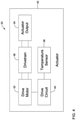
- FIG. 4 is a schematic block diagram of an illustrative fire and smoke actuator 30 that is configured to actuator the damper 12 between an open position and a closed position.
- the fire and smoke actuator 30 includes a drive motor 32 , an actuator output 34 for coupling to the damper 12 in order to move the damper 12 between the open position and the closed position, and a drivetrain 36 that is operably coupled between the drive motor 32 and the actuator output 34 .
- the drive motor 32 may be configured, when actuated, to actuate the actuator output 34 via the drivetrain 36 to move the damper 12 between the open position and the closed position.
- a temperature sensor 38 is configured to sense an operating temperature of the fire and smoke actuator 20 .
- a drive circuit 40 may be operably coupled to the drive motor 32 and to the temperature sensor 38 , and may be configured to activate the drive motor 32 to move the damper 12 between the open position and the closed position at a non-zero speed, wherein the non-zero speed is based, at least in part, on the operating temperature sensed by the temperature sensor 38 .
- a housing 42 may house one or more of the drive motor 32 , the actuator output 34 , the drivetrain 36 , the temperature sensor 38 and the drive circuit 40 .
- the drivetrain 36 is configured to translate rotation of an output shaft of the drive motor 32 into rotation of the actuator output 34 .
- the drivetrain 36 may include one or more gears that are disposed between the drive motor 32 and the actuator output 34 .
- the drivetrain 36 may include one or more components, such as but not limited to these gears, that are more susceptible to wear and/or damage at a higher operating temperature than at a lower operating temperature, and thus the drive circuit 40 may set the non-zero speed lower at the higher operating temperature than at the lower operating temperature.
- the damper 12 may have an end stop
- the drive circuit 40 may be configured to reduce the non-zero speed at the higher operating temperature relative to the non-zero speed at the lower operating temperature when the end stop is reached to help protect the one or more components of the drivetrain 36 that are more susceptible to wear and/or damage at the higher operating temperature when the end stop is reached.
- the non-zero speed may be a linear function of the operating temperature between an upper speed limit and a lower speed limit, meaning that the non-zero speed changes continuously with temperature.
- the non-zero speed may, for example, be a non-linear function of the operating temperature between an upper speed limit and a lower speed limit.
- the non-zero speed may be a step-wise function of the operating temperature between an upper speed limit and a lower speed limit.
- the non-zero speed may be set to a first non-zero speed when the operating temperature is above a temperature threshold and is set to a second non-zero speed when the operating temperature is below the temperature threshold.
- the temperature threshold may, for example, be greater than about 120 degrees F., or about 150 degrees F.
- FIG. 5 provides a graphical representation 50 of how the non-zero speed may be related to temperature.
- Speed is graphed along the Y, or vertical, axis, and temperature is graphed along the X, or horizontal, axis.
- the speed may be equal to an upper speed limit, denoted as 52 .
- the speed may be equal to a lower speed limit, denoted as 54 .
- line 56 indicates what the speed may be that corresponds to any particular temperature that is between the upper speed limit and the lower speed limit. This may be considered as being a continuously changing speed as the measured temperature changes.
- a dashed line 58 provides an example of a stepwise relationship between temperature and speed.
- FIG. 6 is a perspective view of a fire and smoke actuator 70 that includes a housing 72 .
- FIG. 7 is a perspective view of the fire and smoke actuator 70 with at least a portion of the housing 72 removed in order to illustrate internal components.
- the fire and smoke actuator 70 includes an actuator output 74 .
- the fire and smoke actuator 70 includes a gear train 76 including an input gear 78 that is driven by the drive motor (such as the drive motor 32 in FIG. 4 ) and an output gear 80 that drives the actuator output 74 .
- the output gear 80 includes polymeric gear teeth, and/or the entire output gear 80 may be polymeric.
- the input gear 78 includes polymeric gear teeth, and/or the entire input gear 78 may be polymeric.
- One or more of the gears within the gear train 76 may also be metallic.
- the gear train 76 has an overall gear ration that is greater than about 1000:1. This means that for each rotation of the output gear 80 , the input gear rotates at least about 1000 complete revolutions. In some cases, the gear train 76 has a gear ratio of greater than about 2500:1, or even a gear ration of greater than about 5000:1. It will be appreciated that the particular gear ratio may be selected in accordance with the performance characteristics of the drive motor as well as the operational limitations of the damper 12 (how far the damper 12 can rotate, and a size and/or weight of the damper 12 ).
- FIG. 8 is a flow diagram showing an illustrative method 90 of operating a fire and smoke actuator that is configured to actuate a damper.
- the method 90 includes measuring a temperature proximate the fire and smoke actuator, as indicated at block 92 .
- the drive motor of the fire and smoke actuator may be operated at a first operating speed in order to open or close the damper, as indicated at block 94 .
- the drive motor of the fire and smoke actuator may be operated at a second operating speed in order to open or close the damper, the second operating speed being less than the first operating speed as indicated at block 96 .
- the first temperature threshold is the same as the second temperature threshold.
Abstract
Description
Claims (13)
Priority Applications (1)
| Application Number | Priority Date | Filing Date | Title |
|---|---|---|---|
| US16/284,267 US11224777B2 (en) | 2019-02-25 | 2019-02-25 | Fire and smoke actuator with temperature-dependent operating speed |
Applications Claiming Priority (1)
| Application Number | Priority Date | Filing Date | Title |
|---|---|---|---|
| US16/284,267 US11224777B2 (en) | 2019-02-25 | 2019-02-25 | Fire and smoke actuator with temperature-dependent operating speed |
Publications (2)
| Publication Number | Publication Date |
|---|---|
| US20200269077A1 US20200269077A1 (en) | 2020-08-27 |
| US11224777B2 true US11224777B2 (en) | 2022-01-18 |
Family
ID=72142183
Family Applications (1)
| Application Number | Title | Priority Date | Filing Date |
|---|---|---|---|
| US16/284,267 Active 2039-07-25 US11224777B2 (en) | 2019-02-25 | 2019-02-25 | Fire and smoke actuator with temperature-dependent operating speed |
Country Status (1)
| Country | Link |
|---|---|
| US (1) | US11224777B2 (en) |
Citations (28)
| Publication number | Priority date | Publication date | Assignee | Title |
|---|---|---|---|---|
| US5123081A (en) | 1990-07-27 | 1992-06-16 | Raymond Corporation | Temperature control system for motors and power components of a material handling vehicle |
| US5493191A (en) | 1994-09-19 | 1996-02-20 | Eaton Corporation | B-type actuator with time out |
| US5519295A (en) | 1994-04-06 | 1996-05-21 | Honeywell Inc. | Electrically operated actuator having a capacitor storing energy for returning the actuator to a preferred position upon power failure |
| EP0895346A2 (en) | 1997-07-31 | 1999-02-03 | Honeywell Inc. | Drive circuit and method for an electric actuator with spring return |
| EP0861373B1 (en) | 1995-11-14 | 2000-08-30 | Tcam Technologies, Inc. | Proportionally controlled thermochemical mechanical actuator |
| US20040030531A1 (en) | 2002-03-28 | 2004-02-12 | Honeywell International Inc. | System and method for automated monitoring, recognizing, supporting, and responding to the behavior of an actor |
| US20060016201A1 (en) | 2004-07-20 | 2006-01-26 | National Environmental Products, Ltd. | Actuator alarm for critical environments or applications |
| US7033268B2 (en) | 2003-04-17 | 2006-04-25 | Siemens Building Technologies, Inc. | Multi-mode damper actuator |
| US20070118270A1 (en) | 2005-11-18 | 2007-05-24 | General Electric Company | Sensor diagnostics using embedded model quality parameters |
| US20100056039A1 (en) | 2007-04-12 | 2010-03-04 | Belimo Holding Ag | Drive system for a fire protection flap |
| US20100123421A1 (en) | 2008-11-18 | 2010-05-20 | Honeywell International Inc. | Hvac actuator with output torque compensation |
| US20110076131A1 (en) | 2007-03-23 | 2011-03-31 | Johnson Controls Technology Company | Method for detecting rotating stall in a compressor |
| US7922149B2 (en) | 2004-07-29 | 2011-04-12 | Siemens Industry Inc. | Damper actuator assembly |
| US8838413B2 (en) | 2011-05-12 | 2014-09-16 | Saudi Arabian Oil Company | Valve actuator fault analysis system |
| US20140277764A1 (en) | 2013-03-15 | 2014-09-18 | Schneider Electric Buildings, Llc | Advanced valve actuator with integral energy metering |
| US9062893B2 (en) | 2011-05-13 | 2015-06-23 | Johnson Controls Technology Company | Speed adjustment of an actuator for an HVAC system |
| US9067091B2 (en) | 2006-08-25 | 2015-06-30 | Siemens Industry, Inc. | Damper actuator assembly with speed control |
| US9106171B2 (en) | 2013-05-17 | 2015-08-11 | Honeywell International Inc. | Power supply compensation for an actuator |
| US20150323928A1 (en) | 2014-05-08 | 2015-11-12 | Hyundai Motor Company | System and method for diagnosing failure of smart sensor or smart actuator of vehicle |
| US20160049576A1 (en) | 2014-08-15 | 2016-02-18 | Novasentis, Inc. | Actuator structure and method |
| US9372482B2 (en) | 2010-05-14 | 2016-06-21 | Harnischfeger Technologies, Inc. | Predictive analysis for remote machine monitoring |
| US9441547B2 (en) | 2014-06-02 | 2016-09-13 | United Technologies Corporation | Model-based optimal control for stall margin limit protection in an aircraft engine |
| US9667188B2 (en) | 2011-04-05 | 2017-05-30 | Belimo Holding Ag | Flow control actuator |
| US20170152862A1 (en) | 2015-12-01 | 2017-06-01 | Honeywell International Inc. | Method for controlling a trim-adjustment mechanism for a centrifugal compressor |
| US9766638B2 (en) | 2014-12-05 | 2017-09-19 | Goodrich Corporation | Method of detecting an electric actuator with decreased efficiency |
| US20170293293A1 (en) | 2016-04-12 | 2017-10-12 | Johnson Controls Technology Company | Hvac system with equipment failure prediction |
| US9981529B2 (en) | 2011-10-21 | 2018-05-29 | Honeywell International Inc. | Actuator having a test mode |
| US10112727B1 (en) | 2017-08-29 | 2018-10-30 | Kitty Hawk Corporation | Actuator monitoring system using inertial sensors |
-
2019
- 2019-02-25 US US16/284,267 patent/US11224777B2/en active Active
Patent Citations (31)
| Publication number | Priority date | Publication date | Assignee | Title |
|---|---|---|---|---|
| US5123081A (en) | 1990-07-27 | 1992-06-16 | Raymond Corporation | Temperature control system for motors and power components of a material handling vehicle |
| US5519295A (en) | 1994-04-06 | 1996-05-21 | Honeywell Inc. | Electrically operated actuator having a capacitor storing energy for returning the actuator to a preferred position upon power failure |
| US5493191A (en) | 1994-09-19 | 1996-02-20 | Eaton Corporation | B-type actuator with time out |
| EP0861373B1 (en) | 1995-11-14 | 2000-08-30 | Tcam Technologies, Inc. | Proportionally controlled thermochemical mechanical actuator |
| EP0895346A2 (en) | 1997-07-31 | 1999-02-03 | Honeywell Inc. | Drive circuit and method for an electric actuator with spring return |
| US6249100B1 (en) | 1997-07-31 | 2001-06-19 | Honeywell International Inc. | Drive circuit and method for an electric actuator with spring return |
| US20040030531A1 (en) | 2002-03-28 | 2004-02-12 | Honeywell International Inc. | System and method for automated monitoring, recognizing, supporting, and responding to the behavior of an actor |
| US7033268B2 (en) | 2003-04-17 | 2006-04-25 | Siemens Building Technologies, Inc. | Multi-mode damper actuator |
| US20060016201A1 (en) | 2004-07-20 | 2006-01-26 | National Environmental Products, Ltd. | Actuator alarm for critical environments or applications |
| US7922149B2 (en) | 2004-07-29 | 2011-04-12 | Siemens Industry Inc. | Damper actuator assembly |
| US20070118270A1 (en) | 2005-11-18 | 2007-05-24 | General Electric Company | Sensor diagnostics using embedded model quality parameters |
| US7603222B2 (en) | 2005-11-18 | 2009-10-13 | General Electric Company | Sensor diagnostics using embedded model quality parameters |
| US9067091B2 (en) | 2006-08-25 | 2015-06-30 | Siemens Industry, Inc. | Damper actuator assembly with speed control |
| US20110076131A1 (en) | 2007-03-23 | 2011-03-31 | Johnson Controls Technology Company | Method for detecting rotating stall in a compressor |
| US20100056039A1 (en) | 2007-04-12 | 2010-03-04 | Belimo Holding Ag | Drive system for a fire protection flap |
| US20100123421A1 (en) | 2008-11-18 | 2010-05-20 | Honeywell International Inc. | Hvac actuator with output torque compensation |
| US8084982B2 (en) | 2008-11-18 | 2011-12-27 | Honeywell International Inc. | HVAC actuator with output torque compensation |
| US9372482B2 (en) | 2010-05-14 | 2016-06-21 | Harnischfeger Technologies, Inc. | Predictive analysis for remote machine monitoring |
| US9667188B2 (en) | 2011-04-05 | 2017-05-30 | Belimo Holding Ag | Flow control actuator |
| US8838413B2 (en) | 2011-05-12 | 2014-09-16 | Saudi Arabian Oil Company | Valve actuator fault analysis system |
| US9062893B2 (en) | 2011-05-13 | 2015-06-23 | Johnson Controls Technology Company | Speed adjustment of an actuator for an HVAC system |
| US9981529B2 (en) | 2011-10-21 | 2018-05-29 | Honeywell International Inc. | Actuator having a test mode |
| US20140277764A1 (en) | 2013-03-15 | 2014-09-18 | Schneider Electric Buildings, Llc | Advanced valve actuator with integral energy metering |
| US9106171B2 (en) | 2013-05-17 | 2015-08-11 | Honeywell International Inc. | Power supply compensation for an actuator |
| US20150323928A1 (en) | 2014-05-08 | 2015-11-12 | Hyundai Motor Company | System and method for diagnosing failure of smart sensor or smart actuator of vehicle |
| US9441547B2 (en) | 2014-06-02 | 2016-09-13 | United Technologies Corporation | Model-based optimal control for stall margin limit protection in an aircraft engine |
| US20160049576A1 (en) | 2014-08-15 | 2016-02-18 | Novasentis, Inc. | Actuator structure and method |
| US9766638B2 (en) | 2014-12-05 | 2017-09-19 | Goodrich Corporation | Method of detecting an electric actuator with decreased efficiency |
| US20170152862A1 (en) | 2015-12-01 | 2017-06-01 | Honeywell International Inc. | Method for controlling a trim-adjustment mechanism for a centrifugal compressor |
| US20170293293A1 (en) | 2016-04-12 | 2017-10-12 | Johnson Controls Technology Company | Hvac system with equipment failure prediction |
| US10112727B1 (en) | 2017-08-29 | 2018-10-30 | Kitty Hawk Corporation | Actuator monitoring system using inertial sensors |
Non-Patent Citations (1)
| Title |
|---|
| Driker, "Deisign Essentials: Linear Actuators with Thermo-Compensation," Machine Design, 17 pages, May 19, 2017. |
Also Published As
| Publication number | Publication date |
|---|---|
| US20200269077A1 (en) | 2020-08-27 |
Similar Documents
| Publication | Publication Date | Title |
|---|---|---|
| US10900682B2 (en) | HVAC controller with indoor air quality scheduling | |
| US8972064B2 (en) | Actuator with diagnostics | |
| EP1703221B1 (en) | Ventilating system and method for controlling the same | |
| US10744848B2 (en) | Actuator having a test mode | |
| US10113762B2 (en) | Actuator having an adjustable running time | |
| US9194599B2 (en) | Control of multiple environmental zones based on predicted changes to environmental conditions of the zones | |
| US20140206278A1 (en) | Automated fresh air cooling system | |
| US8749182B2 (en) | Actuator having an adjustable auxiliary output | |
| US6495981B2 (en) | Motorized actuator with a variable stall level | |
| US20110253359A1 (en) | System and method for sensing air flow, carbon dioxide or volatile organic compound in residential building | |
| US20190101302A1 (en) | Air pressure controller for air ventilation devices | |
| US20130161403A1 (en) | Hvac system, a controller therefor and a method of measuring and managing ventilation airflow of an hvac system | |
| US9041319B2 (en) | Actuator having an address selector | |
| US20220146135A1 (en) | Damper system control module | |
| US10941876B2 (en) | Retrofit damper control with collapsible blade and remotely actuated latch mechanism | |
| JP6403043B2 (en) | Residential temperature controller | |
| US11224777B2 (en) | Fire and smoke actuator with temperature-dependent operating speed | |
| US10898743B2 (en) | Ventilation closure system | |
| EP2816295B1 (en) | An HVAC system having a diagnostics controller associated therewith | |
| CN107846864B (en) | Animal house climate control system and method for operating an air intake of an animal house using a timed inlet control | |
| EP3519908A1 (en) | Hvac actuator with heating apparatus | |
| AU2016100030A4 (en) | Roof exhaust fan | |
| RU41783U1 (en) | DEVICE FOR NATURAL ROOM VENTILATION | |
| EP1698828A2 (en) | Combustion system, in particular system for regulating a combustion system according to its ventilation or exhaust actual conditions | |
| CN110631236A (en) | Indoor air temperature adjusting method |
Legal Events
| Date | Code | Title | Description |
|---|---|---|---|
| AS | Assignment |
Owner name: HONEYWELL INTERNATIONAL INC., NEW JERSEY Free format text: ASSIGNMENT OF ASSIGNORS INTEREST;ASSIGNORS:FICNER, ONDREJ;SIKORA, LUBOS;BONDU, CHARLES;REEL/FRAME:048425/0521 Effective date: 20190225 |
|
| FEPP | Fee payment procedure |
Free format text: ENTITY STATUS SET TO UNDISCOUNTED (ORIGINAL EVENT CODE: BIG.); ENTITY STATUS OF PATENT OWNER: LARGE ENTITY |
|
| STPP | Information on status: patent application and granting procedure in general |
Free format text: RESPONSE TO NON-FINAL OFFICE ACTION ENTERED AND FORWARDED TO EXAMINER |
|
| STPP | Information on status: patent application and granting procedure in general |
Free format text: NON FINAL ACTION MAILED |
|
| STPP | Information on status: patent application and granting procedure in general |
Free format text: RESPONSE TO NON-FINAL OFFICE ACTION ENTERED AND FORWARDED TO EXAMINER |
|
| STPP | Information on status: patent application and granting procedure in general |
Free format text: FINAL REJECTION MAILED |
|
| STPP | Information on status: patent application and granting procedure in general |
Free format text: DOCKETED NEW CASE - READY FOR EXAMINATION |
|
| STPP | Information on status: patent application and granting procedure in general |
Free format text: NOTICE OF ALLOWANCE MAILED -- APPLICATION RECEIVED IN OFFICE OF PUBLICATIONS |
|
| STPP | Information on status: patent application and granting procedure in general |
Free format text: PUBLICATIONS -- ISSUE FEE PAYMENT RECEIVED |
|
| STPP | Information on status: patent application and granting procedure in general |
Free format text: PUBLICATIONS -- ISSUE FEE PAYMENT VERIFIED |
|
| STCF | Information on status: patent grant |
Free format text: PATENTED CASE |