Field of the Invention
The present invention relates to compact optical components, in particular to three-port
optical circulators.
Background of the Invention
The flexibility of communication networks based on light signals conducted via optical
fibres is greatly increased by the availability of optical fibre-compatible optical components such
as optical circulators. Optical circulators enable light signals to be routed from one optical fibre
to another, and prevent reflected light from returning to the source of the light.
Conventional optical circulators are made of discrete optical elements. As a result, such
optical components are bulky and expensive. A substantial portion of the cost of making such
optical components arises because the elements of such components are physically large and
have to be individually and precisely aligned relative to one another. For example, a recent
catalog published by the Fuji Electrochemical Corporation, Tokyo, Japan shows a Model YC-125A
three-port optical circulator with dimensions of 43 × 30 × 8 mm, excluding the optical
fibre connectors. The large size of these components limits the density with which optical fibre
switching systems can be built.
In High-Isolation Polarization-Insensitive Optical Circulator for Advanced Optical
Communication, 10 J. LIGHTWAVE TECHNOLOGY, 1210-1217 (1992, September) M. Koga and
T. Matsumoto describe an optical circulator based on birefringent crystals, Faraday rotators and
optically-active rotators. However, in the Koga and Matsumoto optical circulator, the lateral
spacing between the input ports is not precisely defined, so the optical circulator divides each
light beam into orthogonal polarization components laterally spaced from one another by about
1.2 mm. This requires the use of birefringent crystals some 12 mm thick. Also, the Koga and
Matsumoto optical circulator uses optically-active rotators about 15.8 mm thick to rotate the
direction of polarization of the polarization components. These large components cause the
Koga and Matsumoto optical circulator to be physically large, and make it unsuitable for use
in applications in which small size and low cost are important.
In United States patent application serial number 08/707,559, assigned to the assignee
of the present application, the inventor disclosed a number of different optical components,
including optical circulators, based on birefringent walk-off crystals. The linear dimensions of
the elements of the optical components disclosed in this patent application are less than one-tenth
of those of the elements of conventional optical components, which resulted in these
optical components being substantially smaller and lower in cost than conventional optical
components.
In the optical circulators disclosed in the inventor's prior application, the fraction of the
light beam received at PORT 1 transmitted to PORT 1' is proportional to cos2 ΔF and the
fraction of the light beam received at PORT 2 transmitted to PORT 1', i.e., the crosstalk
between PORT 2 and PORT 1', is proportional to sin2 ΔF , where ΔF is the rotational alignment
error between the walk-off directions of the opposed walk-off crystal pair of the first I/O port
and the walk-off directions of the opposed walk-off crystal pair of the second I/O port. To
achieve a high transmission factor and low crosstalk requires an accurate rotational alignment
between the first and second I/O ports. This increases the manufacturing cost of such optical
circulators.
To further increase the flexibility of communication networks based on light signals
conducted via optical fibres, it is desirable to increase the density with which optical fibre
switching systems can be built, and to reduce substantially the cost of the optical components
used in such switching systems. Accordingly, it would be advantageous to have a three-port
optical circulator that not only has the considerably smaller size and reduced material cost of
the inventor's previously-disclosed optical circulators, but that is also more tolerant of
manufacturing alignment errors.
Summary of the Invention
The invention provides a miniature three-port optical circulator that comprises a first
input/output (I/O) port, a second I/O port complementary to the first I/O port, and a second
walk-off crystal located between the first I/O port and the second I/O port. The first I/O port
receives two parallel light beams laterally separated from one another in a separation direction
by a separation distance. The first I/O port includes a first walk-off crystal and a split
polarization rotator arranged in order along the optical axis. The first walk-off crystal is located
to receive the light beams and has a first walk-off direction perpendicular to the separation
direction. The split polarization rotator is mounted adjacent the first walk-off crystal and has
a positive half and a negative half. The split polarization rotator is located so that the
polarization components of the light beams that are deviated by the first walk-off crystal pass
through one of the positive half and the negative half, and the polarization components that are
not deviated by the first walk-off crystal pass through the other of the positive half and the
negative half. The second walk-off crystal has a second walk-off direction perpendicular to the
first walk-off direction, and has a walk-off distance equal to the separation distance.
The first I/O port may additionally include a light coupling assembly that defines the
separation direction and separation distance between the two light beams.
The light coupling assembly may include a capillary and two optical fibres secured side-by-side
in the bore of the capillary. The end of the capillary is disposed perpendicular to the bore
and is attached to the surface of the first walk-off crystal remote from the split polarization
rotator. The two optical fibres are secured side-by-side in the bore of the capillary. The optical
fibres each have a diameter of one-half of the diameter of the bore.
The split polarization rotator may include an opposed half-wave plate pair and a 90°
Faraday rotator arranged in either order along the optical axis. The opposed half-wave plate pair
includes a positive half-wave plate and a negative half-wave plate attached to one another at
a line of attachment disposed substantially parallel to the separation direction of the light
beams.
The first walk-off crystal may include a first walk-off crystal element, a second walk-off
crystal element, and a 45° half-wave plate arranged in order along the optical axis. The walk-off
directions of the first walk-off crystal element and of the second walk-off crystal element
are opposite to one another. The first walk-off crystal element and the second walk-off crystal
element have substantially equal walk-off distances totaling the walk-off distance of the first
walk-off crystal. The 45° half-wave plate is located between the first walk-off crystal element
and the second walk-off crystal element.
The invention also provides a miniature three-port optical circulator that comprises a first
I/O port, a second I/O port, and a walk-off crystal, called the second walk-off crystal, located
between the I/O ports. The first I/O port includes a light coupling element, a first walk-off
crystal, and a first split polarization rotator disposed in order along the optical axis. The light
coupling element accurately defines a lateral separation distance and separation direction
between two light beams and that projects the light beams with a small lateral beam spread.
The first walk-off crystal is located to receive the light beams from the light coupling element,
and has a first walk-off direction perpendicular to the separation direction between the light
beams. The first walk-off crystal divides each of the light beams into an orthogonal polarization
component and a parallel polarization component laterally spaced from one another in the first
walk-off direction.
The first split polarization rotator parallelizes the polarization components from the first
walk-off crystal to align the directions of polarization of all four polarization components parallel
to the separation direction. The first split polarization rotator additionally sets perpendicular to
one another initially parallel polarization components perpendicular to one another when such
polarization components pass through the first split polarization rotator in the direction opposite
to the polarization components passing though the first split polarization rotator from the first
walk-off crystal;
The second walk-off crystal has a walk-off direction parallel to the separation direction,
and a walk-off distance substantially equal to the lateral separation distance.
The second I/O port includes a second split polarization rotator and a third walk-off crystal
arranged in order along the optical axis. The second split polarization rotator sets setting the
polarization components from the second walk-off crystal perpendicular to one another. This
aligns the directions of polarization of either (a) the orthogonal polarization components, or (b)
the parallel polarization components, parallel to the first walk-off direction. The second split
polarization rotator additionally parallelizes initially-perpendicular polarization components when
such polarization components pass through the second split polarization rotator in a direction
opposite to the polarization components from the second walk-off crystal. This aligns the
directions of polarization of all four polarization components perpendicular to the separation
direction.
The third walk-off crystal is located to receive the polarization components from the
second split polarization rotator, and operates to combine one of the orthogonal polarization
components and one of the perpendicular polarization components to form an output light
beam. The third walk-off crystal has a third walk-off direction parallel to the first walk-off
direction.
Finally, the invention provides a method of making a miniature optical circulator. In the
method, a walk-off crystal block, a plate pair block, a Faraday rotator block and a perpendicular
walk-off crystal block are provided. Each of the blocks have opposed polished surfaces. The
plate pair block also has a line of attachment. The walk-off crystal block, plate pair block,
Faraday rotator block, and perpendicular walk-off crystal block are stacked on one another with
the polished surfaces juxtaposed, and with a film of adhesive between the juxtaposed polished
surfaces, to form a component block. The component block is divided along multiple dividing
lines oriented in at least one direction perpendicular to the dividing line to form multiple I/O port
assemblies.
The plate pair block may be provided by providing an elongate positive half-wave plate
block and an elongate negative half-wave plate block. Each half-wave plate block has polished
side, top, and bottom surfaces. The positive half-wave plate block has an axis at +22.5° to
its polished side surfaces, the negative half-wave plate block has an axis at -22.5° to its
polished side surfaces. Each of the half-wave plate blocks is divided in half lengthways to
provide two positive half-wave plate halves and two negative half-wave plate halves. Each of
the half-wave plate halves has one polished side surface opposite a rough side surface. Each
of the positive half-wave plate halves is attached to one of the negative half-wave plate halves
with the polished side surfaces of the half-wave plate halves juxtaposed.
Brief Description of the Drawings
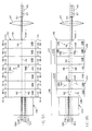
Figures 1A and 1B are respectively side and top views of a first embodiment of the optical
circulator according to the invention.
Figures 1C through 1E are respectively front, side and top views of the first I/O port of the
first embodiment of the optical circulator according to the invention.
Figure 1F is an exploded isometric view of the first I/O port of the first embodiment of the
optical circulator according to the invention.
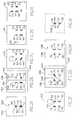
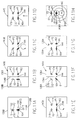
Figures 2A through 2I illustrate the action of the first embodiment of the optical circulator
according to the invention on light passing through the optical circulator in the forward
direction.
Figures 3A through 3I illustrate the action of the first embodiment of the optical circulator
according to the invention on light passing through the optical circulator in the reverse
direction.
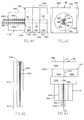
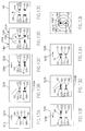
Figures 4A through 4C are respectively top, side and front views of an alternative first I/O
port of the first embodiment of the optical circulator according to the invention.
Figure 4D is a side view showing in more detail the TEC optical fibre used in the alternative
first I/O port shown in Figures 4A through 4C.
Figures 5A and 5B are respectively side and top views of a second embodiment of the
optical circulator according to the invention.
Figures 6A through 6I illustrate the action of the second embodiment of the optical
circulator according to the invention on light passing through the optical circulator in the
forward direction.
Figures 7A through 7I illustrate the action of the second embodiment of the optical
circulator according to the invention on light passing through the optical circulator in the
reverse direction.
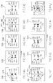
Figures 8A and 8B are respectively side and top views of a third embodiment of an optical
circulator according to the invention in which the path-length difference between the
polarization components is zero.
Figures 9A and 9B are respectively side and top views of a fourth embodiment of an
optical circulator according to the invention in which the path-length difference between the
polarization components is zero.
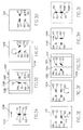
Figures 10A through 10D illustrate the action of the second I/O port of the third and fourth
embodiments of the optical circulator according to the invention on light passing through the
optical circulators in the forward direction.
Figures 11A through 11H illustrate the action of the third and fourth embodiments of the
optical circulator according to the invention on light passing through the optical circulators in
the reverse direction.
Figures 12A and 12B are respectively side and top views of a fifth, fully symmetrical,
embodiment of an optical circulator according to the invention.
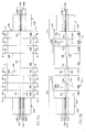
Figures 13A through 13I illustrate the action of the fifth embodiment of the optical
circulator according to the invention on light passing through the optical circulator in the
forward direction.
Figures 14A through 14J illustrate the action of the fifth embodiment of the optical
circulator according to the invention on light passing through the optical circulator in the
reverse direction.
Figure 15 illustrates the method according to the invention of making the plate pair blocks
used in the manufacture of the optical circulators according to the invention.
Figure 16 illustrates the method according to the invention of making multiple miniature
I/O port assemblies from a single component block composed of relatively large optical
components.
Detailed Description of the Invention
Figures 1A and 1B show a side view and a plan view of the general arrangement of a first
embodiment 100 of a compact polarization-independent three-port optical circulator according
to the invention. The optical component 100 includes two complementary compact
input/output (I/O) ports 102 and 112 according to the invention, between which are located
the perpendicular walk-off crystal 145 and the lens 109. The perpendicular walk-off crystal
laterally displaces light passing through the optical circulator in the forward direction relative
to the optical axis, but does not laterally displace light passing through the optical circulator
in the reverse direction.
In the following description, light passing through the optical circulator 100 from the first
I/O port 102 to the second I/O port 112 will be said to pass in the forward direction. Light
passing from the second I/O port to the first I/O port will be said to pass in the reverse
direction.
The optical axis of the lens 109 defines the optical axis 144 of the optical circulator 100.
PORT 2, through which the optical circulator receives the light beam Y, and PORT 3, through
which the optical circulator receives the light beam Z, are located on the optical axis. PORT 1,
through which the optical circulator receives the light beam X, is displaced laterally from the
optical axis by less than about 200 µm in the direction of the lateral axis 158 shown in Figure
1C.
In the forward direction, the optical circulator 100 receives the two input light beams X
and Y via PORT 1 and PORT 2, respectively, transmits the light beam X to PORT 3, and
transmits the light beam Y to a location laterally displaced from PORT 3. In the reverse
direction, the optical circulator receives the input light beam Z via PORT 3 and transmits the
light beam Z to PORT 2.
In the forward direction, the first I/O port 102, operating as an input port, separates the
parallel polarization components of the light beams X and Y from the orthogonal polarization
components of these light beams, transmits the parallel components to two new spatial
locations, each displaced from the optical axes 160 and 162 of the light beams X and Y, and
sets the directions of polarization of the polarization components perpendicular to one another,
aligned with the walk-off direction of the perpendicular walk-off crystal 145. The perpendicular
walk-off crystal laterally displaces both polarization components of both light beams relative
to the optical axis 144. This aligns the polarization components of the light beam X received
via PORT 1 with the optical axis 164 of PORT 3 and displaces the light beam Y received via
PORT 2 to a point laterally displaced from the optical axis of PORT 3. The second I/O port 112
operates as an output port complementarily to the first I/O port to set the directions of
polarization of the parallel and orthogonal polarization components of the light beams X and Y
perpendicular to one another, and to overlay the polarization components of the light beam X
at the location of PORT 3. The second I/O port also overlays the polarization components of
the light beam Y, but at a point laterally displaced from the location of PORT 3. As a result, the
light beam derived from the light beam Y does not enter PORT 3.
In the reverse direction, the second I/O port 112, operating as an input port, separates the
parallel polarization component from the orthogonal polarization component of the light beam
Z, laterally displaces the parallel component to a new spatial location, displaced from the optical
axis 144, and sets the directions of polarization of the polarization components parallel to one
another, aligned perpendicular to the walk-off direction of the perpendicular walk-off crystal
145. The polarization components pass though the perpendicular walk-off crystal without being
laterally displaced. The first I/O port 102 operates as an output port, complementary to the
second I/O port, to set the directions of polarization of the parallel and orthogonal polarization
components of the light beam Z perpendicular to one another, and to overlay the polarization
components of the light beam Z to form a light beam. Since the polarization components are
not laterally displaced by the perpendicular walk-off crystal, the first I/O port overlays the
polarization components of the light beam Z at the location of PORT 2. Any light that enters
the second I/O port outside the location of PORT 3 is transmitted through the optical circulator
100, but leaves the first I/O port from a location outside the location of PORT 2. For example,
light that enters the optical circulator from the location in the second I/O port where the light
beam Y leaves the second I/O port is transmitted to a point having the same lateral
displacement from PORT 2 as PORT 1, but on the opposite side of PORT 2 from PORT 1.
The first I/O port 102 of the first embodiment 100 of the optical circulator will now
be described in more detail with reference to the front, side, top and exploded isometric
views respectively shown in Figures 1C, 1D, 1E and 1F. In Figure 1F, the walk-off crystal
120A, the opposed half-wave plate pair 141A, and the Faraday rotator 143A are exploded
along the optical axis 144, and the half-wave plates 136A and 138A are exploded away
from the line of attachment 134A.
The second I/O port 112 is similar to the first I/O port, and will be described more
detail below. In the following description, corresponding elements of the first I/O port and
the second I/O port are indicated by the same reference numeral with the letter "A" added
to indicate an element of the first I/O port and the letter "B" added to indicate an element
of the second I/O port. This disclosure refers to the same element of both I/O ports using
the appropriate reference numeral without an added letter.
The first I/O port 102 is composed of the walk-off crystal 120A and the split
polarization rotator 122A arranged along the optical axis 144 in the forward direction of
light transmission through the optical circulator 100. The walk-off crystal includes the first
face 124A and the second face 126A, opposite the first face. The first face and the
second face are preferably the major surfaces of the walk-off crystal. The first face 124A
will also be referred to as the first face of the first I/O port. The split polarization rotator
is composed of the opposed half-wave plate pair 141A and the Faraday rotator 143A
arranged in order along the optical axis in the forward direction of light transmission
through the optical circulator. The first face 194A of the Faraday rotator 143A is
preferably attached to the second face 132A of the opposed half-wave plate pair 141A.
The second face 196A of the Faraday rotator will also be referred to as the second face
of the first I/O port 102.
The opposed half-wave plate pair 141A has a first face 130A and a second face
132A, opposite the first face. The first face and the second face are preferably the major
surfaces of the opposed half-wave plate pair. The opposed half-wave plate pair is
composed of the positive half-wave plate 136A and the negative half-wave plate 138A
attached to one another at the line of attachment 134A. In the forward direction of light
transmission through the optical circulator 100, the negative half-wave plate 138A is
located in the walk-off direction 128A of the walk-off crystal 120A relative to the positive
half-wave plate 136A. For example, if the walk-off direction is to the right, the negative
half-wave plate is located to the right of the positive half-wave plate.
In this disclosure, light that passes through the positive half-wave plate 136 of the
split polarization rotator 122 will be said to pass through the positive half of the split
polarization rotator, and light that passes through the negative half-wave plate 138 will be
said to pass through the negative half of the split polarization rotator. Light that passes
through either half-wave plate 136 or 138 before it passes through the Faraday rotator
143 will be said to pass through the split polarization rotator 122 in the forward direction.
Light that passes through the Faraday rotator before it passes through either half-wave
plate will be said to pass through the split polarization rotator in the reverse direction.
The action of the split polarization rotators 122A and 122B will now be described by
describing the action of the split polarization rotator 122A. The action of the split
polarization rotator 122B is the same. As will be described in more detail below, the split
polarization rotator 122A rotates the direction of polarization of light passing through it by
either 0° or 90°, depending on whether the light passes through the positive half-wave
plate 136A or the negative half-wave plate 138A, and depending on whether the light
passes through the split polarization rotator in the forward direction or the reverse
direction.
The direction of the magnetic field (not shown) applied to the Faraday rotator 143A
of the split polarization rotator 122A is chosen so that the Faraday rotator rotates the
direction of polarization of light passing through the optical circulator 100, and through the
split polarization rotator 122A, in the forward direction clockwise by 45° about the
direction of travel of the light. The Faraday rotator is a non-reciprocal device, so rotates
the direction of polarization of light passing through the optical circulator, and through the
split polarization rotator 122A, in the reverse direction anticlockwise by 45° about the
direction of travel of the light.
In the opposed half-wave plate pair 141A, the positive half-wave plate 136A has its
optical axis, indicated by the line 140A, aligned at plus 22.5° relative to the line of
attachment 134A, and the negative half-wave plate 138A has its optical axis, indicated
by the line 142A, aligned at minus 22.5° relative to the line of attachment. In the forward
direction, the positive half-wave plate effectively rotates a polarization component that is
parallel or perpendicular to the line of attachment by 45° anti-clockwise about the direction
of travel of the light. This can be seen by comparing Figures 2B (left-hand half) and 2C.
Figures 2A-2I and 3A-3I will be described in more detail below. The negative half-wave
plate effectively rotates a polarization component that is parallel or perpendicular to the line
of attachment by 45° clockwise about the direction of travel of the light. This can be seen
by comparing Figures 2B (right-hand half) and 2C.
The half-wave plates 136A and 138A are reciprocal devices. Hence, in the reverse
direction, the positive half-wave plate 136A effectively rotates a polarization component
aligned at ± 45° to the line of attachment 134A by 45° anticlockwise about the direction
of travel of the light. This once more aligns the polarization component perpendicular or
parallel, respectively, to the line of attachment 134A. This can be seen by comparing
Figures 3G (right-hand half) and 3H. The negative half-wave plate 138A rotates a
polarization component aligned at ± 45° to the line of attachment by 45° clockwise about
the direction of travel of the light. This once more aligns the polarization component
parallel or perpendicular to the line of attachment. This can be seen by comparing Figures
3G (left-hand half) and 3H.
The split polarization rotator 122A combines the above-described effects of the
opposed half-wave plate pair 141A and the Faraday rotator 143A. Passing in the forward
direction through the positive half of the split polarization rotator leaves unchanged the
direction of polarization of a polarization component initially aligned parallel or perpendicular
to the line of attachment 134A. The direction of polarization is first rotated 45° anticlockwise
by the positive half-wave plate 136A and is then rotated 45° clockwise by the
Faraday rotator. This can be seen in Figures 2B (left-hand half), 2C and 2D. Passing in the
forward direction through the negative half of the split polarization rotator 122A rotates
through 90° the direction of polarization of a polarization component initially aligned
parallel or perpendicular to the line of attachment 134A. The direction of polarization is
first rotated 45° clockwise by the negative half-wave plate 138A, and is then rotated a
further 45° clockwise by the Faraday rotator. This can be seen in Figures 2B (right-hand
half), 2C and 2D. Thus, passing two initially perpendicular polarization components
through the two halves of the split polarization rotator 122A in the forward direction
rotates the direction of polarization of one of the polarization components, but not that of
the other, through 90°, which aligns the directions of polarization of the polarization
components parallel to one another.
Passing in the reverse direction through the positive half of the split polarization
rotator 122A rotates through 90° the direction of polarization of a polarization component
initially aligned parallel or perpendicular to the line of attachment 134A. The direction of
polarization is first rotated 45° anti-clockwise by the Faraday rotator and is then rotated
a further 45° anti-clockwise by the positive half-wave plate 136A. This can be seen in
Figures 3F, 3G (right-hand half) and 3H. Finally, passing in the reverse direction through
the negative half of the split polarization rotator 122A does not change the direction of
polarization of a polarization component initially aligned parallel or perpendicular to the line
of attachment 134A. The direction of polarization is first rotated 45° anti-clockwise by the
Faraday rotator, and is then rotated 45° clockwise by the negative half-wave plate 138.
This can be seen in Figures 3F, 3G (left-hand half) and 3H. Thus, passing two initially
parallel polarization components through the halves of the split polarization rotator 122A
rotates the direction of polarization of one of the polarization components, but not that of
the other, through 90°, which aligns the directions of polarization of the polarization
components perpendicular to one another.
The action of the split polarization rotator may be summarized as follows:
| | Direction of Light Travel Through Split Polarization Rotator |
| | Forward | Reverse |
| Positive Half | 0 | 90 |
| Negative Half | 90 | 0 |
To form the first I/O port 102, the walk-off crystal 120A and the split polarization
rotator 122A are attached to one another with the second face 126A of the walk-off
crystal contacting the first face 130A of the opposed half-wave plate pair 141A. The walk-off
crystal and the split polarization rotator are rotationally oriented so that the walk-off
direction 128A of the walk-off crystal is perpendicular to the line of attachment 134A
between the half-wave plates 136A and 138A constituting the opposed half-wave plate
pair.
In the first I/O port 102, the opposed half-wave plate pair 141A is laterally offset
relative to the walk-off crystal 120A and the Faraday rotator 143A. The direction of the
offset is the walk-off direction 128A of the walk-off crystal. The offset distance is such
that the line of attachment 134A is offset from the axes 160 and 162 of the light beams
X and Y by about one-half of the walk-off distance of the walk-off crystal. Consequently,
in the first embodiment of the optical circulator 100, in which the optical axis 144
coincides with the axis 162 of the light beam Y, the line of attachment 134A of the split
polarization rotator 122A is laterally offset from the optical axis 144 by about on-half of
the above-mentioned walk-off distance.
In Figures 1A, 1B, and 1E, the walk-off direction of each walk-off crystal is indicated
by an arrow showing the walk-off direction for light traveling in the forward direction
through the optical circulator 100. For example, in Figures 1B and 1E, the walk-off
direction of the walk-off crystal 120A for light traveling in the forward direction is from
left to right, as indicated by the arrow 128A. However, the walk-off crystal 128A deflects
light travelling through the optical circulator 100 in the reverse direction in the direction
opposite to that indicated by the arrow, looking in the direction of travel of the light. A
similar convention is used in Figures 4B, 5A, 5B, 8A, 8B, 9A, 9B, 12A, 12B, which show
the structures of the optical circulators according to the invention. In Figures 2A-2I, 3A-3I,
6A-6I, 7A-7I, 10A-10D, 11A-11H and 14A-14J, which show the operation of the optical
circulators according to the present invention, the arrows show the actual direction in
which the walk-off crystals deflect the light.
The opposed half-wave plate pair 141A will be described in greater detail with
reference to Figures 1C-1F. The opposed half-wave plate pair is composed of the positive
half-wave plate 136A and the negative half-wave plate 138A. The half-wave plates 136A
and 138A each include a first face 146A and 148A, respectively, and a second face 150A
and 152A, respectively, parallel to the first face. The first and second faces are preferably
the major faces of the half-wave plates. The first faces 146A and 148A collectively
constitute the first face 130A of the opposed half-wave plate pair. The second faces 150A
and 152A collectively constitute the second face 132A of the opposed half-wave plate
pair. The half-wave plates 136A and 138A also each include an attachment face 154A and
156A, respectively, perpendicular to their first and second faces. The half-wave plates are
attached to one another with their respective attachment faces 154A and 156A in contact
with one another at the line of attachment 134A. The positive half-wave plate 136A has
its optical axis, indicated by the line 140A, aligned at plus 22.5° relative to its attachment
face 154A and the line of attachment 134A. The negative half-wave plate 138A has its
optical axis, indicated by the line 142A, aligned at minus 22.5° relative to its attachment
face 156A and the line of attachment 134A.
The material of the walk-off crystals 120A, 120B and 145 may be rutile (titanium
dioxide―TiO2) or yttrium vanadate (YVO4). The preferred material is rutile. The refractive
index of rutile is greater than that of YVO4, so rutile has a smaller in vacuo path length for
a given walk-off distance. A smaller path length results in less lateral spreading of the
polarization components as they pass through the walk-off crystals.
The required walk-off distance of the walk-off crystals 120A and 120B, and hence
the thickness of these walk-off crystals, depends on the lateral spread of the polarization
components of the light beams X, Y and Z as they pass through the first and second I/O
ports 102 and 112. The walk-off crystals must laterally separate the parallel and
orthogonal polarization components such that none of the polarization components at its
largest lateral spread intersects the line of attachment 134 between the half-wave plates
136 and 138 constituting the opposed half-wave plate pair 122. If any of the polarization
components intersects the line of attachment, diffraction effects at the line of attachment
and interaction between the polarization components will seriously impair the performance
of the optical circulator.
In a practical embodiment, in which the maximum critical radius of the polarization
components at the second face 126 of the I/O port 102 or 112 was about 40 µm, the
walk-off crystals 120A and 120B were rutile and had a thickness of about 1.25 mm. This
gave a walk-off distance of about 125 µm. A similar walk-off distance is obtained using
a YVO4 walk-off crystal of the same thickness. Such a walk-off distance provides a
tolerance of about ± 20 µm on the lateral position of the line of attachment 134 before
one of the polarization components will intersect the line of attachment and diffraction
effects occur.
The other dimensions of the walk-off crystals 120A and 120B are uncritical. In a
practical embodiment, the walk-off crystals 120A and 120B had a length and width of
about 1 mm. The dimensions of the opposed half-wave plate pair 141 were similar. The
half-wave plates consituting the opposed half-wave plate pair were pieces of zero-order
quartz.
The second I/O port 112 is composed of the walk-off crystal 120B and the split
polarization rotator 122B arranged on the optical axis so that light travelling in the forward
direction through the optical circulator 100 passes through the split polarization rotator
first. In the split polarization rotator, the Faraday rotator 143B and the opposed half-wave
plate pair 141B are arranged so that light passing through the optical circulator in the
forward direction passes through the Faraday rotator first. The opposed half-wave plate
pair 141B is displaced laterally from the optical axis 144 in the direction opposite to the
walk-off direction 128B of the walk-off crystal 120B by about one-half of the walk-off
distance of the walk-off crystal.
With respect to light passing in the forward direction through the the first embodiment
100 of the optical circulator, the walk-off direction 128B of the walk-off crystal 120B is
the same as the walk-off direction 128A of the walk-off crystal 120A of the first I/O port
102, the positive half-wave plate 136A of the opposed half-wave plate pair 141B is on the
same side of the optical axis as the positive half-wave plate 136B of the opposed half-wave
plate pair 141A of the first I/O port, and the direction of rotation of the Faraday
rotator 143 is the same in both I/O ports.
Since light passing through the optical circulator 100 in the forward direction passes
through the split polarization rotator 122B of the second I/O port in the reverse direction
of the split polarization rotator, the positive and negative halves of the split polarization
rotator rotate the direction of polarization of polarization components passing through it
by 90° and 0°, respectively. Otherwise, the second I/O port is the same as the first I/O
port and will therefore not be described further.
To enable light passing through the optical circulator 100 in the forward direction to
pass through split polarization rotator 122B of the second I/O port 112 before it passes
through the walk-off crystal 120B, the second I/O port is rotated through 180° relative the
first I/O port 102 about an axis perpendicular to the optical axis 144. The first I/O port
102 and the second I/O port 112 are then mounted on the optical axis 144 with the
second face 196A first I/O port facing the second face 196B second I/O port. The
perpendicular walk-off crystal 145 and the lens 109 are located on the optical axis
between the first I/O port 102 and the second I/O port 112.
When mounting the I/O ports 102 and 112, the location of the I/O ports relative to
the optical axis 144 in the direction perpendicular to the walk-off directions 128 of the
walk-off crystals 120 is uncritical unless the dimensions of the elements of the optical
circulator perpendicular to the optical axis are comparable with the walk-off distances of
the walk-off crystals. In the walk-off directions 128 of the walk-off crystals 120, however,
each I/O port should be aligned so that the line of attachment 134 between the half-wave
plates 136 and 138 is offset from the optical axis in the walk-off direction by about one-half
of the walk-off distance of the walk-off crystal 120. This ensures that the orthogonal
polarization components and the parallel polarization components separated by the walk-off
crystal are spaced approximately equally from the line of attachment. Finally, the first and
second I/O ports are rotationally aligned so that the walk-off direction 128A of the walk-off
crystal 120A and the walk-off direction 128B of the walk-off crystal 120B are parallel
to one another within a small angular tolerance, and so that both walk-off directions are
perpendicular to the lateral axis 158 (shown in Figure 1C) extending between the axes 160
and 162 of the light beams X and Y.
The perpendicular walk-off crystal 145 is aligned with its walk-off direction 166
parallel to the lateral axis 158, within a small angular tolerance. This makes the walk-off
direction of the perpendicular walk-off crystal 145 perpendicular to the walk-off directions
128A and 128B of the walk-crystals 120A and 120B. The perpendicular walk-off crystal
145 has a walk-off distance equal to the length of the lateral axis 158, i.e., equal to the
lateral spacing between the light beams X and Y.
Finally, the lens 109 is located between the perpendicular walk-off crystal 145 and
the second I/O port 112. A gradient-index (GRIN) lens, as shown in the drawings, is
preferred since such a lens is easiest to integrate with the other elements of the optical
circulator 100. Alternatively, other types of converging lens can be used. The lens 109 reconverges
the polarization components, which diverge as they pass through the optical
circulator 100. The focal length of the lens and its spacing from the first faces of the I/O
ports are chosen so that the lens forms an image of the first face 124A of the first I/O port
102 on the first face 124B of the second I/O port 112, and vice versa.
The optical circulator 100 is arranged relative to the light beams X, Y and Z such that
the light beams X and Y impinge perpendicularly on the first face 124A of the first I/O port
102, and the light beam Z impinges perpendicularly on the first face 124B of the second
I/O port 112. The optical circulator is also arranged so that the axes 162 and 164 of the
light beams Y and Z, respectively, coincide with the optical axis 144. As noted above, the
optical circulator is rotationally oriented relative to the light beams X and Y such that the
lateral axis 158 is perpendicular to the walk-off directions 128A and 128B of the walk-off
crystals 120A and 120B, respectively.
As will be described in greater detail below, the cost of making the compact optical
circulator 100 is substantially reduced compared with making a conventional optical
circulator. This is because the optical circulator 100 can be made physically small and can
be manufactured using batch processing. The optical circulator is made physically small
by minimizing the walk-off distance provided by the walk-off crystals 120A, 145 and
120B. This reduces the thickness, and, hence, the other dimensions, of the walk-off
crystals. The walk-off distance is minimized by making the spacing between the light
beams X and Y as small as possible. This requires that the light beams be accurately
located relative to one another and relative to the lines of attachment 134A and 134B, and
also requires that the lateral spread of the light beams be minimized. Moreover, the
spacing between the light beams must also be accurately defined relative to the walk-off
distance of the perpendicular walk-off crystal 145 to minimize transmission loss in the
forward direction.
Figures 4A-4D show an embodiment 108 of a modified I/O port in which the direction
of, and spacing between, the light beams X and Y is defined by the I/O port itself. The
light beams X and Y are coupled to the I/O port using optical fibres whose optical axes are
accurately parallel and precisely spaced relative to one another, and that are accurately
positioned spatially and rotationally relative to the elements of the I/O port.
A version of the modified I/O port 108 that can be substituted for the first I/O port
102 in the optical circulator 100 shown in Figures 1A-1F will now be described with
reference to Figures 4A-4D. Elements of the modified I/O port 108 corresponding to those
of the first I/O port 102 are indicated using the same reference numerals, and will not be
described in detail here.
The modified I/O port 108 may readily be adapted so that it can also be substituted
for the second I/O port 112 in the optical circulator 100. When used as a second I/O port,
the modified I/O port 108 requires only one active optical fibre, the on-axis optical fibre
106. This is because the second I/O port includes only PORT 3, whereas the first I/O port
includes PORT 1 and PORT 2. The off-axis optical fibre 104 may be of minimal length.
Alternatively, a piece of scrap optical fibre, or a length of glass rod having the same
outside diameter as that of the on-axis optical fibre 106 may be used as the off-axis optical
fibre when the modified I/O port 108 is used as a second I/O port.
The modified I/O port 108 includes the walk-off crystal 120A and the split polarization
rotator 122A, as in the I/O port 102. The first I/O port additionally includes the light
coupling assembly 110A that locates the light beams X and Y, transmitted via the optical
fibres 104A and 106A, respectively, at a precisely-defined distance and orientation relative
to one another. The light coupling assembly also locates the light beams X and Y in a
precisely-defined spatial and rotational relationship to the optical axis 144 and the line of
attachment 134A between the half-wave plates 136A and 138A constituting the opposed
half-wave plate pair 141A.
The optical fibres 104A and 106A are both thermally-diffused, expanded-core (TEC)
single-mode optical fibres and are housed in the bore 116A of the capillary 118A. The
optical fibre 104A will be described in detail with reference to Figure 4D. The optical fibre
106A is identical, and will not be described. The optical fibre 104A is a TEC optical fibre
in which the core 105A of the fibre has a substantially constant diameter over most of the
length of the fibre. A small part of constant-diameter portion of the optical fibre is
indicated by the reference numeral 107A. In the expansion region 111A, adjacent the end
113A of the optical fibre that abuts the walk-off crystal 120A, the diameter of the core
progressively expands to reach a maximum diameter at the end 113A of the fibre. The
expansion factor of the core is typically in the range of 3-5, and the expansion region
typically has a length in the range of 4-6 mm.
The expanded core 105A of the TEC optical fibre 104A reduces the angle at which
the light emitted from the end 113A of the fibre spreads laterally compared with a
conventional optical fibre. The reduction in the angle at which the light spreads is about
equal to the expansion factor. The reduced lateral spreading of the light beam emitted by
a TEC optical fibre enables the spacing between the centers of two adjacent TEC optical
fibres to be substantially reduced. In the preferred embodiment, the spacing is reduced to
the distance corresponding to the outside diameter of the optical fibres. This puts the
outside surfaces of the optical fibres in contact one another, as shown in Figure 4A, for
example. Even with this small spacing between the optical fibres, the critical radius of the
polarization components of the light beams emitted by the optical fibres as the polarization
components pass through the opposed half-wave plate pair 141A is small enough to allow
a tolerance of a few tens of microns on the alignment between the optical fibres and the
line of attachment 134A. This enables the lateral axis 158 to be mounted a few tens of
microns out of alignment with the line of attachment before the polarization components
of the light beam emitted by one of the optical fibres intersects the line of attachment
134A. As noted above, minimizing the spacing between the light beams enables the size
and cost of the optical circulator to be significantly reduced.
The low lateral spread of the light beam emitted by a TEC optical fibre 104A offers
the possibility of eliminating the need to converge the light emitted by the optical fibre on
the end of the optical fibre (not shown) corresponding to the optical fibre 104A in the
second I/O port . However, even though the lateral beam spread obtained with present
TEC optical fibres is small, not converging the light causes a substantial intensity loss.
Therefore, it is preferred that the lens 109 be used to converge the light beams, even
when the modified I/O port 108 is used. The lens forms an image of the end of the core
of the optical fibre 104A on the end of the core of the corresponding optical fibre (not
shown) of the second I/O port, and forms an image of the core of the corresponding
optical fibre of the second I/O port on the end of the optical fibre 106A of the first I/O
port.
In the preferred embodiment, the optical fibres 104A and 106A each have an outside
diameter of 125 µm, the mode field diameter of the constant-diameter region 107A of the
core is about 10 µm, the maximum mode field diameter of the core is about 40 µm, and
the length over which the core expands from its constant diameter to its maximum
diameter is about 5 mm. With this arrangement, the radius of the full-width half maximum
of each polarization component increases from about 20 µm at the first face 124A of the
walk-off crystal 120A to about 25 µm at the second face 132A of the opposed half-wave
plate pair 141A. This maintains an adequate clearance between the maximum radius of the
polarization components and the line of attachment 134A. When the light coupling
assembly is centered on the line of attachment, the center of the each polarization
component is about 62 µm from the line of attachment.
The two optical fibres 104A and 106A coupled to the modified I/O port 108 are
mounted in the bore 116A of the capillary 118A. The diameter of the bore 118A is a few
microns greater than the sum of the outside diameters of the optical fibres 104A and
106A. A bore with this diameter relationship to the outside diameters of the optical fibres
accommodates and accurately locates the optical fibres parallel to one another. Inserting
the optical fibres, which have a known and accurately-defined outside diameter, into the
bore of the capillary, which has a known and precisely-defined diameter, aligns the optical
axes 160 and 162 of the optical fibres accurately parallel to one another and precisely
defines the distance between the optical axes of the optical fibres. In the preferred
embodiment, the capillary 118A has an outside diameter of 1 mm, a length of 10 mm and
its bore has a diameter of 254 µm. The diameter of the bore is four microns larger than
the sum of the outside diameters of the optical fibres 104A and 106A.
The light coupling assembly 110A is attached to the first face 124A of the walk-off
crystal 120A with the optical axis 162 of the optical fibre 106A centered on the optical
axis 144A. This aligns the light beams X and Y relative to the line of attachment 134A
such that the orthogonal and parallel polarization components of the light beams enter the
opposed half-wave plate pair 141A symmetrically disposed about the line of attachment
134A.
The light coupling assembly 110A is attached to the first face 124A of the walk-off
crystal 120A so that it is rotationally oriented such that the lateral axis 158 (Figure 4C)
that interconnects the optical axes 160 and 162 of the optical fibres 104A and 106A,
respectively, is perpendicular to the walk-off direction 128A of the walk-off crystal 120A.
The rotational alignment of the light coupling assembly is preferably done actively. Both
optical fibres are illuminated, and the positions of the four polarization components leaving
the second face 196A of the I/O port are checked using suitable magnification. The light
coupling assembly is rotated relative to the walk-off crystal until the four polarization
components form a perfect rectangle.
The operation of the optical circulator 100 will now be described with reference to
Figures 2A-2I and 3A-3I. The operation of the optical circulator is the same irrespective
of whether the I/O ports 102 and 112 shown in Figures 1A-1F are used or whether
modified I/O ports similar to the I/O port 108 are used.
Figures 2A-2I and 3A-3I show the polarization components of the light beams X, Y,
Z and S at various points in the optical circulator 100 indicated by the section lines 2A-2A
through 2I-2I and 3A-3A through 3I-3I in Figure 1A. Figures 2A-2I show the polarization
components at the indicated points in the optical circulator when the light beams X and
Y pass through the optical circulator in the forward direction. Figures 3A-3I show the
polarization components at the indicated points in the optical circulator when the light
beam Z and the spurious light beam S pass through the optical circulator in the reverse
direction. In both sets of figures, the views are in the direction in which the light passes
through the optical circulator.
Figure 2A shows the light beams X and Y as they enter the first I/O port 102, i.e., at
the first face 124A of the walk-off crystal 120A. The light beam X is shown as having an
orthogonal polarization component O1, indicated by a long, thick bar, and a parallel
polarization component P1, indicated by a short, thick bar. The light beam Y is shown as
having an orthogonal polarization component O2, indicated by a long, thin bar, and a
parallel polarization component P2, indicated by a short, thin bar. The orthogonal
polarization components O1 and O2 are the polarization components of the light beams
X and Y that are perpendicular to the walk-off direction 128A of the walk-off crystal 120A
of the first I/O port. The parallel polarization components P1 and P2 are the polarization
components of the light beams X and Y that are parallel to the walk-off direction 128A.
In the walk-off crystal 120A, the axis 162 of the light beam Y coincides with the
optical axis 144, whereas the axis 160 of the light beam X is laterally displaced from the
optical axis in the direction perpendicular to the walk-off direction 128A of the walk-off
crystal. The orthogonal polarization components O1 and O2 are perpendicular to the walk-off
direction 128A of the walk-off crystal 120A, and so pass through the walk-off crystal
without deviation. The parallel polarization components P1 and P2, on the other hand, are
parallel to the walk-off direction of the walk-off crystal. The walk-off crystal therefore
deviates the parallel polarization components in its walk-off direction. Figure 2B shows the
polarization components as they enter the split polarization rotator 122A from the walk-off
crystal 120A.
In the split polarization rotator 122A, the parallel polarization components P1 and P2
are respectively located at the displaced locations 170 and 172 to the right of the optical
axis 144. The locations 170 and 172 are respectively displaced relative to the locations
160 and 162 of the orthogonal polarization components O1 and O2 by the walk-off
distance of the walk-off crystal 120A in the walk-off direction 128A of the walk-off
crystal. As noted above, the split polarization rotator 122A is displaced laterally from the
optical axis 144 in the walk-off direction 128A of the walk-off crystal 120A by about one-half
of the walk-off distance of the walk-off crystal. Consequently, the orthogonal
polarization components O1 and O2 enter the positive half of the split polarization rotator
122A and the parallel polarization components P1 and P2 enter the negative half of the
split polarization rotator at points symmetrically disposed about the line of attachment
134A.
The direction of polarization of the orthogonal polarization components O1 and O2 is
unchanged by these polarization components passing through the positive half of the split
polarization rotator 122A. The direction of polarization of the parallel polarization
components P1 and P2 is rotated through 90° by these polarization components passing
through the negative half of the split polarization rotator. Figure 2D shows the polarization
components as they enter the perpendicular walk-off crystal 145 from the split polarization
rotator 122A. Figure 2C shows the polarization components as they enter the Faraday
rotator 143A from the opposed half-wave plate pair 141A.
The split polarization rotator 122A rotating the direction of polarization of only the
parallel polarization components P1 and P2 sets the directions of polarization of all four
polarization components parallel to the walk-off direction 166 of the perpendicular walk-off
crystal 145. The perpendicular walk-off crystal displaces each of the polarization
components in its walk-off direction by its walk-off distance, which is equal to the spacing
between the light beams X and Y along the lateral axis 158 (Figure 1C). Consequently, the
perpendicular walk-off crystal laterally displaces the orthogonal polarization component O1
of the light beam X to a position corresponding to the axis 162 of the light beam Y. The
perpendicular walk-off crystal also laterally displaces the parallel component P1 of the light
beam X to the displaced location 172. Finally, the perpendicular walk-off crystal displaces
the orthogonal polarization component O2 and the parallel component P2 of the light beam
Y to the displaced locations 174 and 176, respectively. The displaced location 174 lies on
an extension of the lateral axis 158 (see Figure 1C) and is displaced from the axis 162 by
the walk-off distance of the perpendicular walk-off crystal 145. The displaced location 176
is displaced from the axis 162 by the combined walk-off distances of the walk-off crystals
145 and 120A. The perpendicular walk-off crystal does not change the directions of
polarization of the polarization components. Figure 2E shows the polarization components
as they enter the lens 109 from the perpendicular walk-off crystal.
The lens 109 inverts the positions of the polarization components O1, P1, O2 and P2
about the optical axis 144. Since the orthogonal polarization component O1 lies on the
optical axis, the lens leaves the position of this polarization component unchanged. The
axis 164 of PORT 3 coincides with the optical axis, so the lens leaves the orthogonal
polarization component O1 aligned with PORT 3. The lens inverts the position of the
orthogonal polarization component O2 about the optical axis to a position corresponding
to the axis 160 of the light beam X, and inverts the positions of the parallel polarization
components P1 and P2 and the light beams X and Y, respectively, about the optical axis
to the displaced locations 178 and 180. The displaced location 178 is displaced from the
optical axis 144 in the direction opposite to the walk-off direction of the walk-off crystal
120A by the walk-off distance of this walk-off crystal. The displaced location 180 is
displaced from the optical axis 144 in the direction opposite to the combined walk-off
directions of the walk-off crystals 120A and 145 by the combined walk-off distances of
these walk-off crystals.
Figure 2F shows the polarization components as they enter the second I/O port 112
from the perpendicular walk-off crystal 145. The polarization components enter the
opposed half-wave plate pair 122B, which is laterally offset from the optical axis in the
direction opposite to the walk-off direction of the walk-off crystal 120B. This aligns the
orthogonal polarization components O1 and O2 with the negative half of the split
polarization rotator 122B, and aligns the parallel polarization components P1 and P2 with
the positive half of the split polarization rotator. The orthogonal polarization components
and the parallel polarization components are symmetrically disposed about the line of
attachment 134B of the opposed half-wave plate pair 141B.
The polarization components passing through the optical circulator 100 in the forward
direction pass through the split polarization rotator 122B of the second I/O port in the
reverse direction of the split polarization rotator. Consequently, the direction of polarization
of the orthogonal polarization components O1 and O2 is unchanged by the polarization
components passing through the negative half of the split polarization rotator 122B. The
direction of polarization of the parallel polarization components P1 and P2 is rotated
through 90° by the polarization components passing through the positive half of the split
polarization rotator.
Figure 2H shows the polarization components as they enter the walk-off crystal 120B
from the split polarization rotator 122B. The split polarization rotator rotating the direction
of polarization of the parallel polarization components P1 and P2 sets the directions of
polarization of the parallel polarization components perpendicular to their respective
orthogonal polarization components O1 and O2 , and aligns the parallel polarization
components parallel to the walk-off direction 128B of the walk-off crystal 120B. Figure 2G
shows the polarization components as they enter the opposed half-wave plate pair 141B
from the Faraday rotator 143B.
The walk-off crystal 120B deflects the parallel polarization components P1 and P2 by
its walk-off distance in its walk-off direction 128B. The walk-off crystal passes the
orthogonal polarization components O1 and O2 without deflecting them. The walk-off
distance of the walk-off crystal 120B is such that the parallel polarization component P1
of the light beam X is overlaid on the orthogonal polarization component O1 of the light
beam X at the location of the axis 164 of PORT 3, and the parallel polarization component
P2 of the light beam Y is overlaid on the parallel polarization component O2 of the light
beam Y at the location of the axis 160, laterally displaced from PORT 3. Thus, only the
light beam X entering the optical circulator via PORT 1 is transmitted to PORT 3. The light
beam Y entering the optical circulator via PORT 2 is transmitted to a point laterally
displaced from PORT 3, and so does not enter PORT 3.
In the preferred embodiment, the parallel polarization components P1 and P2 enter the
walk-off crystal 128B laterally displaced from the orthogonal polarization components O1
and O2, respectively, by a distance equal to the walk-off distance of the walk-off crystal
128A. The respective polarization components are overlaid by making the walk-off
distance of the walk-off crystal 128B equal to that of the walk-off crystal 128A.
The operation of the optical circulator 100 in the reverse direction will now be
described with reference to Figures 3A-3I. These figures show the polarization components
of the light beam Z and the spurious light beam S at various points in the optical circulator
100 indicated by the section lines 3A-3A through 3I-3I in Figure 1A. The views are all in
the direction in which the light passes through the optical circulator. The spurious light
beam S enters the second I/O port 112 of the optical circulator aligned with the axis 160
of the PORT 1 of the first I/O port, i.e., at the location in the second I/O port from which
the light beam Y leaves the optical circulator in the forward direction
Figure 3A shows the light beams Z and S as they enter the second I/O port 112. The
light beam Z enters the second I/O port at PORT 3, i.e., along the axis 164, and is shown
as having an orthogonal polarization component O1, indicated by a long, thick bar, and a
parallel polarization component P1, indicated by a short, thick bar. The spurious light beam
enters the second I/O port along the axis 160, and is shown as having an orthogonal
polarization component O2, indicated by a long, thin bar, and a parallel polarization
component P2, indicated by a short, thin bar.
In the walk-off crystal 120B, the orthogonal polarization components O1 and O2 are
perpendicular to the walk-off direction 128B of the walk-off crystal 120B, and so pass
through the walk-off crystal without deviation. The parallel polarization components P1 and
P2 are parallel to the walk-off direction of the walk-off crystal, and so are deviated by the
walk-off crystal. Figure 3B shows the polarization components as they enter the split
polarization rotator 122B from the walk-off crystal 120B.
The parallel polarization components P1 and P2 are respectively located at the
displaced locations 172 and 170 to the right of the optical axis 144 as they enter the split
polarization rotator 122B. The locations 172 and 170 are displaced relative to the locations
164 and 160 of the orthogonal polarization components O1 and O2 by the walk-off
distance of the walk-off crystal 120B in the walk-off direction 128B of the walk-off crystal.
As noted above, the opposed half-wave plate pair 141B is displaced laterally from the
optical axis 144 in the walk-off direction 128B of the walk-off crystal 120B by a distance
of about one-half of the walk-off distance of the walk-off crystal. This causes the
orthogonal polarization components to enter the negative half of the split polarization
rotator, and the parallel polarization components enter the positive half of the split
polarization rotator, at locations symmetrically disposed about the line of attachment 134B
of the opposed half-wave plate pair 141B.
The polarization components passing through the optical circulator 100 in the reverse
direction pass through the split polarization rotator 122B of the second I/O port in the
forward direction of the split polarization rotator. Consequently, the direction of
polarization of the parallel polarization components P1 and P2 is unchanged by these
polarization components passing through the positive half of the split polarization rotator.
The direction of polarization of the orthogonal polarization components O1 and O2 is
rotated through 90° by these polarization components passing through the negative half
of the split polarization rotator.
Figure 3D shows the polarization components as they enter the lens 109 from the
second I/O port 112. The split polarization rotator 122B rotating the direction of
polarization of the orthogonal polarization components O1 and O2 sets the directions of
polarization of all four polarization components perpendicular to the walk-off direction 166
of the perpendicular walk-off crystal 145. Figure 3C shows the polarization components
as they enter the Faraday rotator 143B from the opposed half-wave plate pair 141B.
The lens 109 inverts the positions of the polarization components O1, P1, O2 and P2
about the optical axis 144. Since the orthogonal polarization component O1 of the light
beam Z lies on the optical axis 144, the lens leaves the position of this polarization
component unchanged. The axis 162 of PORT 2 coincides with the optical axis, so the
lens leaves this polarization component aligned with PORT 2. The lens inverts the positions
of the orthogonal polarization component O2 and the parallel components P1 and P2 to
the displaced locations 182, 184 and 186, respectively. Figure 3E shows the polarization
components as they enter the perpendicular walk-off crystal 145 from the lens.
Since the directions of polarization of all four polarization components O1, P1, O2 and
P2 are perpendicular to the walk-off direction 166 of the perpendicular walk-off crystal
145, all four polarization components pass through the perpendicular walk-off crystal
without any change in their positions or directions of polarization. Figure 3F shows the
polarization components as they enter the first I/O port 102 from the perpendicular walk-off
crystal.
The orthogonal polarization components and the parallel polarization components enter
the first I/O port 102 aligned with the positive half and the negative half, respectively, of
the split polarization rotator 122A, and disposed symmetrically about the line of
attachment 134A. The polarization components passing through the optical circulator 100
in the reverse direction pass through the split polarization rotator 122A of the first I/O port
108 in the reverse direction of the split polarization rotator. Consequently, the direction
of polarization of the orthogonal polarization components O1 and O2 is rotated through
90° by the polarization components passing through the positive half of the split
polarization rotator. The direction of polarization of the parallel polarization components
P1 and P2 is unchanged by the polarization components passing through the negative half
of the split polarization rotator 122A.
Figure 3H shows the polarization components as they enter the walk-off crystal 120A
from the split polarization rotator 122A. The split polarization rotator rotating the direction
of polarization of the orthogonal polarization components O1 and O2 sets the directions
of polarization of the orthogonal polarization components perpendicular to those of their
respective parallel polarization components P1 and P2. The parallel polarization
components remain parallel to the walk-off direction 128A of the walk-off crystal 120A.
Figure 3G shows the polarization components as they enter the opposed half-wave plate
pair 141A from the Faraday rotator 143A.
The walk-off crystal 120A deflects the polarization components P1 and P2 by its
walk-off distance in the direction of its walk-off direction 128A, and passes the orthogonal
polarization components O1 and O2 without deflecting them. The relationship between the
walk-off distances of the walk-off crystals 120A and 120B is such that the parallel
polarization component P1 of the light beam Z is overlaid on the orthogonal polarization
component O1 of the light beam Z at the location of the axis 162, i.e., at PORT 2, and the
parallel polarization component P2 of the light beam S is overlaid on the parallel
polarization component O2 of the light beam S at the displaced location 182. The
displaced location 182 is laterally displaced from both PORT 1 and PORT 2, so only the
light beam Z entering the optical circulator via PORT 3 is transmitted to PORT 2. The
spurious light beam S entering the optical circulator at the location corresponding to the
exit location of the light beam Y in the forward direction is transmitted to neither PORT 1
nor PORT 2.
When light passes through the optical circulator 100 in the forward direction, the
optical circulator should ideally transmit 100% of the light beam X and 0% of light beam
Y to PORT 3, i.e., the optical circulator should have a transmission factor of unity and
cross-talk of zero. However, the transmission factor and crosstalk of a practical optical
circulator are degraded by errors in the components of the I/O ports, and by angular
misalignment between the I/O ports and the perpendicular walk-off crystal 145. The
transmission factor and crosstalk are degraded by the walk-off directions of the walk-off
crystals 120A and 120B not being exactly perpendicular to the walk-off direction of the
perpendicular walk-off crystal 145, and by the split polarization rotators 122A and 122B
not rotating the directions of polarization of the polarization components by exactly 0° or
90°.
In the forward direction, the above-mentioned errors in the first I/O port 102 align the
direction of polarization one or more of the polarization components O1, P1, O2 and P2
at a non-zero angle Δ 1 to the walk-off direction 166 of the perpendicular walk-off crystal
145. The non-zero angle Δ 1 between the direction of a polarization component and the
walk-off direction 166 results in the polarization component having a component
perpendicular to the walk-off direction. This component, which will be called the error
component of the polarization component, is not deflected by the perpendicular walk-off
crystal. The amplitude of this component is proportional to sin2 Δ 1 . A non-zero angle
between the directions of polarization of the polarization components O1 and P1 of the
light beam X and the walk-off direction 166 of the perpendicular walk-off crystal 145
degrades the transmission factor of the optical circulator 100 with respect to the light
beam X. The degradation is proportional to cos2 Δ 1 .
The perpendicular walk-off crystal 145 does not deflect the error components of the
polarization components O1 and P1 of the light beam X from the locations 160 and 170
to the locations 162 and 172, respectively. Consequently, part of the light beam X, i.e.,
the error components, is not deflected to the locations 162 and 172 whence the light
beam X is transmitted to PORT 3. Thus, the intensity of the light beam X at PORT 3 is
reduced.
A non-zero angle between the directions of polarization of the polarization components
O2 and P2 of the light beam Y and the walk-off direction 166 of the perpendicular
walk-off crystal 145 also degrades the cross-talk of the optical circulator 100. The
perpendicular walk-off crystal does not deflect the error components of the polarization
components of the light beam Y from the locations 162 and 172 to the locations 174 and
176, respectively. Instead, the error components remain at the locations 162 and 172,
where they are mixed with the polarization components of the light beam X deflected from
the locations 160 and 170. Thus, the polarization components of the light beam X entering
the second I/O port from the perpendicular walk-off crystal 145 include the error
components of the light beam Y.
Errors in the first I/O port 102 reduce the transmission factor of, and increase cross-talk
in, the polarization components of the light beam X entering the second I/O port 112
from the perpendicular walk-off crystal 145. However, the transmission factor and cross-talk
of the optical circulator 100 with respect to the light beam X are not determined solely
by the transmission factor and cross-talk of the first I/O port. The second I/O port 112
decreases the transmission factor by a small amount and decreases the cross-talk of the
optical circulator 100 compared with the transmission factor and cross-talk at the output
of the perpendicular walk-off crystal.
The second I/O port 112 reduces the cross-talk at the output of the perpendicular
walk-off crystal 166 by attenuating the error components EO2 and EP2 of the light beam Y
in the light beam X. When the split polarization rotator 122B of the second I/O port rotates
the direction of polarization of the polarization components O1 and P1 of the light beam
X, it also rotates the error components EO2 and EP2 in the polarization components O1 and
P1, respectively. Consequently, the error components are aligned parallel and perpendicular,
respectively, to the walk-off direction 128B of the walk-off crystal 120B. The walk-off
crystal 120B deflects the polarization component P1, which aligns P1 with PORT 3.
However, the walk-off crystal does not deflect the error component EP2, so the error
component EP2 does not enter PORT 3. The walk-off crystal 120B passes the orthogonal
polarization component O1 without deflecting it, which keeps the orthogonal polarization
component aligned with PORT 3. However, the walk-off crystal deflects the error
component EO2 away from PORT 3, so the error component EO2 does not enter PORT 3.
By similarly rotating the direction of polarization of the error components of the light
beam X, the second I/O port 112 changes the transmission factor with respect to the light
beam X.
In a practical embodiment of the optical circulator 100, the components of second I/O
port 112 are subject to the same types of errors as the corresponding components of the
first I/O port 102. Consequently, unless the error components in the orthogonal and
parallel polarization components are respectively exactly parallel and perpendicular to the
walk-off direction 128B of the walk-off crystal 120B, the second I/O port will transmit a
fraction of the error component in each polarization component to PORT 3. The fraction
of the error component transmitted to PORT 3 depends on the angle Δ 2 between the
direction of polarization of the error component and the direction parallel or perpendicular
to the walk-off direction 128B.
The overall transmission factor of the optical circulator 100, i.e., the fraction of the
light beam X transmitted to PORT 3, is given by: IX cos2 Δ 1 cos2 Δ 2 , where IX is the
intensity of the light beam X. The cross-talk of the optical circulator 100, i.e., the fraction
of the light beam Y transmitted to PORT 3, is given by: IY sin2 Δ 1 sin2 Δ 2 , where IY is the
intensity of the light beam Y. The additional attenuation of crosstalk by the second I/O port
provides acceptable cross-talk performance despite a substantial angular alignment errors
between the polarization components and the walk-off directions of the perpendicular
walk-off crystal 145 and the walk-off crystal 120B. For example, with Δ 1 and Δ 2 in the
range of ±2°, the crosstalk will be below -60dB, and with Δ 1 and Δ 2 in the range of
±5°, the crosstalk will be below - 40dB.
The transmission factor of the optical circulator 100 for the light beam Z in the
reverse direction, and the crosstalk from the spurious light beam S into PORT 2 depend
similarly on the angular misalignments Δ 1 and Δ 2.
In the first embodiment 100 of the optical circulator just described, only the parallel
polarization components P1 and P2 are deviated by the walk-off crystals 120A and 120B.
The orthogonal polarization components O1 and O2 pass through these walk-off crystals
without deviation. This results in an optical path length difference between the polarization
components of the light beams X, Y and Z. If the modulation rate of the light beam is high
enough for this optical path length difference between its polarization components to
degrade performance, a birefringent crystal (not shown) can be included in either or both
the first I/O port 102 or 108 and the second I/O port 112. The birefringent crystal is
preferably located between the walk-off crystal 120 and the split polarization rotator 122.
The birefringent crystal is orientated with its higher refractive index direction aligned
perpendicular to the walk-off direction 128. If the walk-off crystal 120 has a thickness of
a and a refractive index difference of Δn 1, and the birefringent crystal has a refractive
index difference of Δn 2, then the birefringent crystal should have a thickness of aΔn 1/Δn 2.
A second embodiment 200 of the optical circulator according to the invention is
shown in Figures 5A and 5B, and its operation is shown in Figures 6A-6I (forward
direction) and 7A-7I (reverse direction). In the second embodiment 200, the orthogonal
and parallel polarization components of the light beams X, Y and Z have equal path
lengths. In the second embodiment of the optical circulator, elements that are the same
as those of the first embodiment are indicated using the same reference numerals and will
not be described further. Elements that are similar are indicated using the same reference
numerals increased by 100.
In the optical circulator 200, the perpendicular walk-off crystal 145 and lens 109 are
identical to the perpendicular walk-off crystal and lens, respectively, of the first
embodiment 100. The first I/O port 208 includes the walk-off crystal 120A and the split
polarization rotator 222A, and preferably includes the light coupling assembly 110A. The
first I/O port 208 differs from the first I/O port 108 described above with reference to
Figures 4A-4D in that the light coupling assembly is laterally offset in the direction
perpendicular to the lateral axis 158 (Figure 1C). This offsets PORT 1 and PORT 2 laterally
from the optical axis 144 defined by the lens 109. The light coupling assembly is offset
from the optical axis in the direction opposite to the walk-off direction 128A of the walk-off
crystal 120A by about one-half of the walk-off distance of the walk-off crystal. To
centralize the light beams in the elements of the first I/O port, the walk-off crystal 120A
and the split polarization rotator 222A are preferably centered on the optical axis 144.
The second I/O port 218 is structurally similar to the first I/O port 208. The light
coupling assembly 110B is laterally offset so that PORT 3 is offset from the optical axis
144 in the walk-off direction of the walk-off crystal 120B by about one-half of the walk-off
distance of the walk-off crystal. The walk-off crystal 120B and the split polarization rotator
222B are preferably centered on the optical axis. The split polarization rotator 222B is
similar to the split polarization rotator 222A.
With respect to light passing in the forward direction through the second embodiment
200 of the optical circulator, the walk-off direction 128B of the walk-off crystal 120B of
the second I/O port 218 is opposite to the walk-off direction 128A of the walk-off crystal
120A of the first I/O port 208, the positive half wave plate 136A of the opposed half-wave
plate pair 141B is on the opposite side of the optical axis from the positive half wave
plate 136B of the opposed half-wave plate pair 141A of the first I/O port, and the direction
of rotation of the Faraday rotator 143 is the same in both I/O ports.
The light coupling assemblies 110A and 110B may be omitted from the I/O ports 208
and 218 if the lateral spacing between the light beams X and Y is otherwise accurately
defined, and the light beams X, Y and Z have an acceptably low lateral spread, as
discussed above.
The perpendicular walk-off crystal 145 is also preferably centered on the optical axis
144.
Operation of the optical circulator 200 on the light beams X and Y passing in the
forward direction from PORT 1 to PORT 3 is illustrated in Figures 6A-6I using the same
conventions as in Figures 2A-2I. The operation of the first I/O port 208 and the
perpendicular walk-off crystal 145 on the polarization components of the light beams X
and Y is shown in Figures 6A-6E. Since this operation is the same as that described above
with reference to Figures 2A-2E, it will not be described again here. The lateral offset of
PORT 1 and PORT 2 from the optical axis 144 does not change the operation of this part
of the optical circulator, but does change the positions of axes 160 and 162 and the
displaced locations 170 and 172 relative to the optical axis 144.
The lens 109 inverts the positions of the polarization components O1, P1, O2 and P2
about the optical axis 144. Since the orthogonal polarization component O1 and the
parallel polarization component P1 of the light beam X respectively enter the lens located
at the locations 162 and 172 symmetrically disposed about the optical axis, the lens
interchanges the positions of the polarization components of the light beam X about the
optical axis, as can be seen by comparing Figures 6E and 6F. Thus, the orthogonal and
parallel polarization components O1 and P1 of the light beam X leave the lens and enter
the second I/O port 218 at the displaced locations 172 and 162, respectively. These are
the locations at which the polarization components of the light beam Y entered the
perpendicular walk-off crystal 145, as shown in Figure 6D. The displaced location 162
corresponds to the axis 164 of PORT 3.
The lens 109 also inverts the positions of the orthogonal and parallel polarization
components O2 and P2 of the light beam Y about the optical axis 144. Thus, again as
shown in Figure 6F, the orthogonal and parallel polarization components O2 and P2
respectively leave the lens and enter the second I/O port 218 at the locations 170 and
160. These are the locations at which the polarization components of the light beam X
entered the perpendicular walk-off crystal 145, as shown in Figure 6D.
As the polarization components enter the second I/O port 218 from the lens 109, the
orthogonal polarization components O1 and O2 are aligned with the positive half of the
split polarization rotator 222B, and the parallel polarization components P1 and P2 are
aligned with the negative half of the split polarization rotator. The orthogonal polarization
components and the parallel polarization components are symmetrically disposed about the
line of attachment 134B of the opposed half-wave plate pair 141B, as shown in Figure 6F.
The polarization components passing through the optical circulator 200 in the forward
direction pass through the split polarization rotator 222B of the second I/O port 218 in the
reverse direction of the split polarization rotator. Consequently, the direction of polarization
of the orthogonal polarization components O1 and O2 is rotated through 90° by the
polarization components passing through the positive half of the split polarization rotator
222B. The direction of polarization of the parallel polarization components P1 and P2 is
unchanged by the polarization components passing through the negative half of the split
polarization rotator. Figure 6H shows the polarization components as they enter the walk-off
crystal 120B from the split polarization rotator 222B. The split polarization rotator
rotating the direction of polarization of the orthogonal polarization components O1 and O2
sets the directions of polarization of the orthogonal polarization components perpendicular
to their respective parallel polarization components P1 and P2, and aligns the orthogonal
polarization components parallel to the walk-off direction 128B of the walk-off crystal
120B. Figure 6G shows the polarization components as they enter the opposed half-wave
plate pair 141B from the Faraday rotator 143B.
The walk-off crystal 120B deflects the orthogonal polarization components O1 and
O2 by its walk-off distance in its walk-off direction 128B. The walk-off crystal passes the
parallel polarization components P1 and P2 without deflecting them. The walk-off distance
of the walk-off crystal 120B is such that the orthogonal polarization component O1 of the
light beam X is overlaid on the parallel component P1 of the light beam X at the location
of the axis 164 of PORT 3. The walk-off distance of the walk-off crystal 120B is also such
that the orthogonal polarization component O2 of the light beam Y is overlaid on the
parallel polarization component P2 of the light beam Y at the location of the axis 160,
laterally displaced from PORT 3.
The paths of the orthogonal and parallel polarization components O1 and P1 of the
light beam Y as they pass through the optical circulator 200 are shown in Figure 5B. The
orthogonal polarization component is indicated by the dash line 186 and the parallel
polarization component is indicated by the dash-dot line 188. Only the parallel polarization
component is deflected laterally by the walk-off crystal 120A in the first I/O port 208,
whereas only the orthogonal polarization component is deflected by the walk-off crystal
120B in the second I/O port 218. This results in a zero path length length difference
between the polarization components.
The operation of the optical circulator 200 in the reverse direction is illustrated in
Figures 7A-7I. These figures show the polarization components O1 and P1 of the light
beam Z and the polarization components O2 and P2 of the spurious light beam S at
various points in the optical circulator 200 indicated by the section lines 7A-7A through
7I-7I in Figure 5A. The views are all in the direction in which the light passes through the
optical circulator. The spurious light beam S enters the second I/O port of the optical
circulator at exit point of the light beam Y in the forward direction.
The light beams Z and S enter the walk-off crystal 120B at the locations 164,
corresponding to the axis of PORT 3, and 160, respectively. The walk-off crystal 120B
deflects the parallel polarization components P1 and P2 in the direction of its walk-off
direction 128B. This aligns the parallel polarization components P1 and P2 with the
positive half of the split polarization rotator 222B and aligns the orthogonal polarization
components O1 and O2 with the negative half of the split polarization rotator 222B. The
polarization components passing through the optical circulator 200 in the reverse direction
pass through the split polarization rotator 222B of the second I/O port 208 in the forward
direction of the split polarization rotator. Consequently, the split polarization rotator rotates
the direction of polarization of the orthogonal polarization components, but not that of the
parallel polarization components, though 90°, as can be seen by comparing Figures 7B
and 7D.
The lens 109 inverts the positions of the polarization components about the optical
axis 144. As a result, the polarization components O1, P1, O2 and P2 respectively enter
the perpendicular walk-off crystal 145 at the locations 172, 162, 176 and 174, with their
directions of polarization perpendicular to the walk-off direction 166. The location 162 of
PORT 2 in the first I/O port corresponds to the axis 164 of PORT 3 in the second I/O port.
This is shown in Figure 7E. None of the polarization components is rotated or deflected
by the perpendicular walk-off crystal 145, as shown in Figure 7F.
In the first I/O port 208, the orthogonal polarization components O1 and O2 are
aligned with the negative half of the split polarization rotator 222A, and the parallel
polarization components are aligned with the positive half of the split polarization rotator.
The polarization components passing through the optical circulator 200 in the reverse
direction pass through the split polarization rotator 222A in the reverse direction of the
split polarization rotator. Consequently, the split polarization rotator rotates the direction
of polarization of the parallel polarization components P1 and P2, but not that of the
orthogonal polarization components O1 and O2, through 90°. This sets the directions of
polarization of the parallel polarization components perpendicular to those of their
respective orthogonal polarization components. The orthogonal polarization components
remain parallel to the walk-off direction 128A of the walk-off crystal 120A.
Figure 7H shows the polarization components as they enter the walk-off crystal 120A
from the split polarization rotator 222A. Figure 7G shows the polarization components as
they enter the opposed half-wave plate pair 141A from the Faraday rotator 143A.
The walk-off crystal 120A deflects the orthogonal polarization components O1 and
O2 by its walk-off distance in the direction of its walk-off direction 128A, and passes the
parallel polarization components P1 and P2 without deflecting them. This overlays the
orthogonal polarization component O1 of the light beam Z on the parallel polarization
component P1 of the light beam Z at the location of the axis 162, i.e., at PORT 2, as
shown in Figure 7I. This also overlays the orthogonal polarization component O2 of the
light beam S on the parallel polarization component P2 of the light beam S at the displaced
location 174, which is laterally displaced from both PORT 1 and PORT 2. Thus, only the
light beam Z entering the optical circulator via PORT 3 is transmitted to PORT 2. The
spurious light beam S is transmitted to neither PORT 1 nor PORT 2.
The lateral offset between PORT 1, PORT2 and PORT 3 and the optical axis 144
requires the lens 109 to be a low astigmatism lens. The simplest way to reduce the
astigmatism of the lens 109 is to increase focal length of the lens. This requires that the
spacing between the lens and the first faces of the first and second I/O ports 208 and 218
be increased, which increases the physical size of the optical circulator 200.
Two alternative embodiments of the zero path-length difference optical circulator are
shown in Figures 8A-8C, 9A and 9B. In these Figures, elements corresponding to the
embodiments shown in Figures 1A and 5A are indicated using the same reference
numerals. In the embodiment 300 shown in Figures 8A-8C, and the embodiment 400
shown in Figure 9A and 9B, the first I/O port 208 and the perpendicular walk-off crystal
145 are identical to the corresponding elements shown in Figure 5A, and will not be
described again here.
In both embodiments 300 and 400, the second I/O ports 318 and 412 are similar to
the second I/O port 112 shown in Figures 1A and 1B, but differ in that the optical axis
164 of PORT 3 is offset from the optical axis 144, and in that the second I/O port 318
includes the light coupling assembly 110B. The offset is in the walk-off direction 128B of
the walk-off crystal 120B and the offset distance is about one-half of the walk-off distance
of the walk-off crystal 120B. This places PORT 3 on the opposite side of the optical axis
from PORT 1 and PORT 2. The second I/O ports 318 and 412 also differ from the second
I/O port 112 in that the opposed half-wave plate pair 222B is preferably centered on the
optical axis 144, as in the second I/O port 218.
Both of the embodiments 300 and 400 lack the lens 109.
In the embodiment 300 shown in Figure 8A-8C, the perpendicular walk-off crystal
145 is spaced from the second I/O port 318, and the converging four-element microlens
array 301 is located adjacent the second face 190 of the perpendicular walk-off crystal.
Alternatively, the perpendicular walk-off crystal may be spaced from the first I/O port 302,
and the microlens array may be located adjacent the first face 192 of the perpendicular
walk-off crystal. Microlens arrays with a spacing of 250 µm between the optical axes of
adjacent lenses 303 and 305, and 303 and 307 are available from Nippon Sheet Glass Co.
The I/O ports may be easily modified to double the spacing between the optical axes 160
and 162 and to double the walk-off distance of the walk-off crystals 120A and 120B. With
this change, each of the four lenses 303, 305, 307 and 309 in the microlens array is
centered on the axis of one of the polarization components O1, P1, O2 and P2 as the
polarization components leave the perpendicular walk-off crystal. The focal length of the
lenses in the microlens array, and the spacing between the first face 124A of the walk-off
crystal 120A and the first face 124B of the walk-off crystal 120B are chosen so that the
microlenses form an image of PORT 1 at PORT 3 and forms an image of PORT 3 at PORT
2.
In the embodiment 400 shown in Figures 9A and 9B, the perpendicular walk-off
crystal 145 is mounted in contact with both the first I/O port 208 and the second I/O port
412, so that the first I/O port 208, the second I/O port 318 and the perpendicular walk-off
crystal 145 all form a monolithic block. The converging lens 411 is located adjacent the
first face 124B of the walk-off crystal 120B with its optical axis aligned with the optical
axis 164 of PORT 3, i.e., laterally offset from the optical axis 144. Although the
conventional bi-convex lens shown in Figures 9A and 9B can be used as the lens 411, a
cylindrical gradient index (GRIN) lens is preferred, since this type of lens is easier to mount
in this embodiment. Other suitable types of lens, such as a ball lens, can alternatively be
used.
The converging lens 411 converges the light leaving PORT 3 on the end 413 of the
optical fibre 415, and converges the light leaving the end of the optical fibre on PORT 2.
Preferably, the optical fibre 415 is a single-mode fibre. The focal length of the lens, the
spacing between the first face 124B of the walk-off crystal 120B and the lens, and the
spacing between the lens and the optical fibre 415 are chosen so that the lens forms an
image of PORT 1 on the end 413 of the optical fibre and forms an image of the core 417
of the optical fibre at PORT 2.
In the embodiments shown in Figures 1A, 5A and 8A, the polarization components
of the light beams X and Y diverge as they pass through the optical circulator from PORT
1 and PORT 2. However, the polarization components are re-converged part-way throught
the optical circulator by the lens 109 or the lens array 301 before they pass through the
opposed half-wave plate pair 141B in the second I/O port. Similarly, the polarization
components of the light beam Z diverge as they pass through the optical circulator from
PORT 3, but are re-converged before they pass through the opposed half-wave plate pair
141A. However, in the embodiment shown in Figures 9A and 9B, the polarization
components diverge as they pass through the optical circulator from PORT 1, but are not
re-converged before they reach the opposed half-wave plate pair 141B. Consequently, in
this embodiment, greater precautions must be taken to prevent the polarization
components from intersecting the line of attachment 134B of the opposed half-wave plate
pair 141B. These precautions may include further reducing the angle of divergence of the
polarization components as they enter the optical circulator, reducing the allowed tolerance
on the offset between the line of attachment 134B and the optical axis 144, and
increasing the walk-off distance of the walk-off crystals 120A and 120B.
The operation of the embodiments 300 and 400 shown in Figures 8A, 8B, 9A and 9B
will now be described with reference to Figures 6A-6D, 10A-10D and 11A-11H using the
same conventions as in Figures 2A-2I. In the forward direction, the operation of the first
I/O port 208 and the perpendicular walk-off crystal 145 on the polarization components
of the light beams X and Y is the same as that described above with reference to Figures
2A-2E and as shown in Figures 6A-6E, so will not be described again here.
The operation of the second I/O ports 318 and 412 of the embodiments 300 and 400
is shown in Figures 10A-10D. Figure 10A shows the polarization components O1, P1, O2
and P2 as they enter the second I/O port from the perpendicular walk-off crystal 145. The
orthogonal polarization component O1 enters the positive half of the split polarization
rotator 222B at the location 164, which corresponds to the optical axis of PORT 2. The
parallel polarization component P1 enters the negative half of the split polarization rotator
at the location 164, which corresponds to the optical axis of PORT 3. The polarization
components O2 and P2 respectively enter the positive and negative halves of the split
polarization rotator at the displaced locations 174 and 176, respectively. The opposed half-wave
plate pair 122B is centered on the optical axis. Consequently, the orthogonal
polarization components and the parallel polarization components are symmetrically
disposed about the line of attachment 134B of the opposed half-wave plate pair 141B.
The polarization components passing through the optical circulators 300 and 400 in
the forward direction pass through the split polarization rotator 222B in the reverse
direction of the split polarization rotator. Consequently, the direction of polarization of the
orthogonal polarization components O1 and O2 is rotated through 90° by the polarization
components passing through the positive half of the split polarization rotator. The direction
of polarization of the parallel polarization components P1 and P2 remains unchanged by
these polarization components passing through the negative half of the split polarization
rotator.
Figure 10C shows the polarization components as they enter the walk-off crystal
120B from the split polarization rotator 222B. The split polarization rotator rotating the
direction of polarization of the orthogonal polarization components O1 and O2 the sets the
directions of polarization of the orthogonal polarization components perpendicular to those
of their respective parallel polarization components P1 and P2, and aligns the orthogonal
polarization components parallel to the walk-off direction 128B of the walk-off crystal
120B. Figure 10B shows the polarization components as they enter the opposed half-wave
plate pair 141B from the Faraday rotator 143B in the split polarization rotator 222B.
The walk-off crystal 120B deflects the orthogonal polarization components O1 and
O2 by its walk-off distance in its walk-off direction 128B. The walk-off crystal passes the
parallel polarization components P1 and P2 without deflecting them. The walk-off distance
of the walk-off crystal 120B is such that the orthogonal polarization component O1 of the
light beam X is overlaid on the parallel component P1 of the light beam X at the location
of the axis 164, i.e., at PORT 3, and the orthogonal polarization component O2 of the light
beam Y is overlaid on the parallel polarization component P2 of the light beam Y at the
location 176, laterally displaced from PORT 3. This is shown in Figure 10D. Thus, only the
light beam X is transmitted to PORT 3. The light beam Y is transmitted to a point laterally
offset from PORT 3, and no light from the light beam Y enters PORT 3.
The action of the embodiments 300 and 400 on light passing in the reverse direction
is illustrated in Figures 11A-11H. These figures show the polarization components O1 and
P1 of the light beam Z and the polarization components O2 and P2 of the spurious light
beam S at various points in the optical circulators 300 and 400 indicated by the section
lines 11A-11H through 11H-11H in Figures 8A and 9A. The views are all in the direction
in which the light passes through the optical circulator. The spurious light beam S enters
the second I/O port of optical circulator at the displaced location 176, corresponding to
the exit point of the light beam Y in the forward direction.
In the reverse direction, the walk-off crystal 120B deflects the parallel polarization
components P1 and P2 in its walk-off direction 128B. This aligns the parallel polarization
components with the positive half of the split polarization rotator 222B and aligns the
orthogonal polarization components O1 and O2 with the negative half of the split
polarization rotator. The polarization components passing through the optical circulators
300 and 400 in the reverse direction pass through the split polarization rotator 222B of
the second I/O ports 218 and 412, respectively, in the forward direction of the split
polarization rotator. Consequently, the split polarization rotator rotates the direction of
polarization of the orthogonal polarization components, but not that of the parallel
polarization components, though 90°, as can be seen by comparing Figures 11B and 11D.
Figure 11C shows the polarization components as they enter the Faraday rotator 143B
from the opposed half-wave plate pair 141B.
The polarization components enter the perpendicular walk-off crystal 145 with their
directions of polarization perpendicular to the walk-off direction 166. This is shown in
Figure 11D. None of the polarization components is rotated or deflected by the
perpendicular walk-off crystal.
After passing through the perpendicular walk-off crystal 145, the orthogonal
polarization components O1 and O2 are aligned with the negative half of the split
polarization rotator 222A of the first I/O port 208, and the parallel polarization components
are aligned with the positive half of the split polarization rotator. The polarization
components passing through the optical circulators 300 and 400 in the reverse direction
pass through the split polarization rotator 222A in the reverse direction of the split
polarization rotator. Consequently, the split polarization rotator rotates the direction of
polarization of the parallel polarization components, but not that of the orthogonal
polarization components, through 90°. This sets the directions of polarization of the
parallel polarization components P1 and P2 perpendicular to those of the orthogonal
polarization components O1 and O2. The directions of polarization of the orthogonal
polarization components remain parallel to the walk-off direction 128B of the walk-off
crystal 120B, as shown in Figure 11G.
The walk-off crystal 120B deflects the orthogonal polarization components O1 and
O2 by its walk-off distance in its walk-off direction 128B, and passes the parallel
polarization components P1 and P2 without deflecting them. The orthogonal polarization
component O1 of the light beam Z is overlaid on the parallel polarization component P1
of the light beam Z at the location of the axis 162, i.e., at PORT 2, as shown in Figure
11H. Also, the orthogonal polarization component O2 of the light beam S is overlaid on
the parallel polarization component P2 of the light beam S at a location corresponding to
the displaced location 174. The displaced location 174 is laterally displaced from both
PORT 1 and PORT 2. Thus, only the light beam Z entering the optical circulator via PORT
3 is transmitted to PORT 2. The spurious light beam S is transmitted to neither PORT 1
nor PORT 2.
A fully symmetrical embodiment 500 of the optical circulator according to the
invention is shown in Figures 12A and 12B. In the embodiment 500, the orthogonal and
parallel polarization components of the light beams X, Y and Z have equal path lengths,
and PORT 2 and PORT 3 are located on the optical axis 144. Elements in the embodiment
500 that are the same as those of the embodiment 200 shown in Figures 5A and 5B are
indicated using the same reference numerals and will not be described further.
In the optical circulator 500, the perpendicular walk-off crystal 145 and lens 109 are
the same as the perpendicular walk-off crystal and lens, respectively, of the embodiment
200 shown in Figures 5A and 5B. The lens arrangements shown in Figures 8A and 8B,
and in Figures 9A and 9B may alternatively be used. The first I/O port 508 differs from the
first I/O port 208 in that the compound walk-off crystal 520A is substituted for the walk-off
crystal 120A. The compound walk-off crystal 520A is composed of the walk-off crystal
element 521A, the 45° half-wave plate 523A, and the walk-off crystal element 525A
arranged in order along the optical axis 144 in the forward direction of light transmission.
The walk-off crystal elements 521A and 523A preferably have equal thicknesses, and
hence equal walk-off distances. The total of the walk-off distances of the walk-off crystal
elements 521A and 523A is equal to the desired lateral separation between the orthogonal
and parallel polarization components. For example, in an embodiment corresponding to the
embodiment 200 described above with reference to Figures 5A and 5B, in which the walk-off
crystal 120A had a thickness of 1.25 mm, the thickness of the walk-off crystal
elements 521A and 525A was 0.612 mm. This arrangement provided the same lateral
separation between the polarization components as the walk-off crystal 120A in the
embodiment 200.
The walk-off crystal elements 521A and 525A are mounted with their walk-off
directions opposite to one another, and perpendicular to the lateral axis 158 extending
between the optical axes 160 and 162 of PORT 1 and PORT 2 (see Figure 1C). The walk-off
direction 527A of the walk-off crystal element 521A is directed towards the positive
half-wave plate 136A in the split polarization rotator 222A. The walk-off direction 529A
of the walk-off crystal element 525A is towards the negative half-wave plate 138A in the
split polarization rotator 222A.
The first I/O port 508 further differs from the first I/O port 208 in that the positive
half-wave plate 136A is preferably located to the right of the optical axis 144 relative to
the forward direction of light transmission. Alternatively, the positive half-wave plate to
the left of the optical axis, in which case, the walk off directions of the walk-off crystal
elements 521A and 523A are reversed so that the walk off direction 527A of the walk-off
crystal element 521A is still directed towards the positive half-wave plate 136A, and the
walk off direction 529A of the walk-off crystal element 525A is still directed towards the
negative half-wave plate 138A.
The second I/O port 512 is similar to the first I/O port 508. With respect to light
passing in the forward direction through the embodiment 500 of the optical circulator, the
walk-off direction 527B of the walk-off crystal 521B is the same as the walk-off direction
527A of the walk-off crystal 521A of the first I/O port, the walk-off direction 529B of the
walk-off crystal 525B is the same as the walk-off direction 529A of the walk-off crystal
525A, the positive half-wave plate 136B of the opposed half-wave plate pair 141B is on
the same side of the optical axis as the positive half-wave plate 136A of the opposed half-wave
plate pair 141A of the first I/O port, and the direction of rotation of the Faraday
rotator 143 is the same in both I/O ports.
Operation of the optical circulator 500 on the light beams X and Y passing in the
forward direction from PORT 1 to PORT 3 is illustrated in Figures 13A-13J using the same
conventions as in Figures 2A-2I.
The light beams X and Y respectively enter the first I/O port 508 along the axes 160,
corresponding to PORT 1, and 162, corresponding to PORT 2. The axis 162 coincides
with the optical axis 144. This is shown in Figure 13A. The walk-off crystal element 521A
deflects the parallel polarization components P1 and P2 in its walk-off direction 527A by
its walk-off distance to the displaced locations 531 and 533, respectively, as shown in
Figure 13B.
The polarization components enter the 45° half-wave plate 523A. The half-wave plate
rotates the direction of polarization of each of the polarization components through 90°,
as shown in Figure 13C. This aligns the parallel polarization components P1 and P2
perpendicular to, and the orthogonal polarization components O1 and O2 parallel to, the
walk-off direction 529A of the walk-off crystal 525A.
The walk-off crystal element 525A deflects the orthogonal polarization components
O1 and O2 in its walk-off direction 529A by its walk-off distance to the displaced locations
535 and 537, respectively. Since the walk-off distance and walk-off direction of the walk-off
crystal element 525A are equal and opposite to the walk-off distance and walk-off
direction of the walk-off crystal element 521A, the walk-off crystal element 525A deflects
the orthogonal polarization components equally and opposite to the deflection of the
parallel polarization components. This disposes the parallel polarization components and
the orthogonal polarization components symmetrically about the line of attachment 134A
of the opposed half-wave plate pair 541A forming part of the split polarization rotator
222A, as shown in Figure 13D.
The parallel polarization components P1 and P2 pass through the positive half of the
split polarization rotator 222A, which leaves their direction of polarization unchanged. The
orthogonal polarization components O1 and O2 pass through the negative half of the split
polarization rotator 222A, which rotates their direction of polarization by 90°. As a result,
the polarization components enter the perpendicular walk-off crystal 145 with their
directions of polarization parallel to the walk-off direction 166 of this walk-off crystal. The
locations 531, 533, 535 and 537 of the polarization components P1, P2, O1 and O2
relative to the optical axis 144 correspond to the locations 170, 172, 160 and 162,
respectively, of the same polarization components in the embodiment 200 shown in Figure
6D.
Since the perpendicular walk-off crystal 145, the lens 109 and the split polarization
rotator 222B in the embodiment 500 are the same as the corresponding elements of the
embodiment 200 shown in Figures 5A and 5B, and since the polarization components
enter the perpendicular walk-off crystal 145 of the embodiment 500 in the same locations
relative to the optical axis as they enter the perpendicular walk-off crystal in the
embodiment 200, the operation of the perpendicular walk-off crystal 145, the lens 109
and the split polarization rotator 222B in the embodiment 500 is the same as that
described above with reference to Figures 6E-6G, and will not be described again here.
Figure 13F shows the polarization components as they enter the compound walk-off
crystal 520B from the split polarization rotator 222B in the second I/O port 518. The
parallel polarization components P1 and P2 are perpendicular to, and the orthogonal
polarization components O1 and O2 are parallel to, the walk-off direction 529B of the
walk-off crystal element 525B. The orthogonal polarization components O1 and O2 are
located at the locations 172 and 170, respectively, and the parallel polarization
components P1 and P2 are located at the locations 537 and 535, respectively.
The walk-off crystal element 525B deflects the orthogonal polarization components
in its walk-off direction 529B by its walk-off distance. This locates the orthogonal
polarization component O1 at the axis 164 of PORT 3. The axis 164 coincides with the
optical axis in this embodiment. This also locates the orthogonal polarization component
O2 at the location 160, as shown in Figure 13G.
The polarization components enter the 45° half-wave plate 523B from the walk-off
crystal 525B. The half-wave plate rotates the direction of polarization of each polarization
component through 90°, as shown in Figure 13H. This aligns the orthogonal polarization
components O1 and O2 perpendicular to, and the parallel polarization components P1 and
P2 parallel to, the walk-off direction 527B of the walk-off crystal element 521B.
The walk-off crystal element 521B deflects the parallel polarization components P1
and P2 in its walk-off direction 527B by its walk-off distance. The walk-off crystal element
passes the orthogonal polarization components O1 and O2 without deflecting them. The
total of the walk-off distances of the walk-off crystal elements 521B and 525B is such that
the parallel polarization component P1 of the light beam X is overlaid on the orthogonal
polarization component O1 of the light beam X at the location of the axis 164, i.e., at
PORT 3, and the parallel polarization component P2 of the light beam Y is overlaid on the
parallel polarization component O2 of the light beam Y at the location of the axis 160,
laterally displaced from PORT 3. Thus, only the light beam X entering the optical circulator
via PORT 1 is transmitted to PORT 3.
Figures 14A-14J illustrate the operation of the optical circulator 500 on light passing
in the reverse direction from PORT 3 to PORT 2. Since the operation of the elements of
the optical circulator 500 should by now be well understood, these Figures will not be
separately described.
A process for making the optical circulators according to the invention is illustrated
in Figures 16A- 16D. The small size of the walk-off crystals, half-wave plates and Faraday
rotators constituting the optical circulators described in this disclosure means that the
optical circulators would be tedious and expensive to assemble individually. However, the
simple structure of the optical circulators enables them to be easily and inexpensively
made in batches.
First, the method according to the invention of making the plate pair blocks used in
the manufacture of the optical circulators according to the invention will be described with
reference to Figure 15. Elongate half-wave plate blocks having square or rectangular cross
section are commercially available. These half-wave plate blocks are available with faces
that are polished, accurately parallel or perpendicular to one another, and accurately
oriented at a defined angle relative to the optical axis of the half-wave plate block.
However, to reduce costs, the ends of the half-wave plate blocks need not be polished.
Unpolished surfaces are indicated by shading throughout Figure 15.
In a practical embodiment, two half-wave plate blocks 701A and 701B, each about
1 mm wide, 1 mm thick and 10 mm long, as shown in (A) of Figure 15, were used. In the
following description, corresponding elements of the half-wave plate blocks 701A and
701B are indicated by the same reference numeral with the letter A or B, respectively,
added. If no letter is added to a reference numeral referring to an element of the half-wave
plate blocks 701A and 701B, or to the half-wave plate blocks themselves, the reference
is to be understood to refer to both half-wave plate blocks.
Each half-wave plate block 701A and 701B includes the polished side surface 713
and the polished side surface 714 opposite the polished side surface 713. Each half-wave
plate block also includes the polished top surface 732, perpendicular to the polished side
surfaces 713 and 714, and the polished bottom surface 733, opposite the polished top
surface.
The half-wave plate block 701 A has its optical axis 731A oriented at -22.5° relative
to the polished side surface 713A, the half-wave plate block 701B has its optical axis
731B oriented at +22.5 ° relative to the polished side surface 713B.
The half-wave plate block 701A is divided lengthways along the line 703A in a first
dividing operation. This provides two half-wave plate halves 705A and 707A shown in (B).
The half-wave plate block is preferably divided by sawing, but other suitable ways of
dividing half-wave plate blocks, such as cleaving, may be used. The half-wave plate halves
705A and 707A each have a rough surface 709A and 711A, respectively, as a result of
the dividing operation. The half-wave plate 701B is similarly divided to yield the half-wave
plate halves 705B and 707B having the rough surfaces 709B and 711B, respectively.
As shown in (B), the optical axes 715A and 717A of the half-wave plate halves
obtained by dividing the half-wave plate block 701A are parallel to one another, and the
optical axes 715B and 717Bof the half-wave plate halves obtained by dividing the half-wave
plate block 701B are parallel to one another, but are angled at 45° to the optical
axes 715A and 717A.
Referring briefly to Figures 1C and 1F, the opposed half-wave plate pair 122 is
composed of one positive half-wave plate 136 whose axis is oriented at +22.5° to the
line of attachment 134, and one negative half-wave plate 138 whose axis is oriented at
-22.5° to the line of attachment. The polarization components pass through the opposed
half-wave plate pair 141 within a few tens of microns of the line of attachment between
the half-wave plates 136 and 138. To reduce diffraction of the polarization components
at the line of attachment, it is preferred that the attachment faces 154 and 156, where the
half-wave plates are joined to one another, be smooth and polished.
To make opposed half-wave plate pairs each composed of one positive half-wave
plate and one negative half-wave plate attached to one another at smooth attachment
surfaces without the need for additional polishing, a first plate pair block 723-1 is made
from the half-wave plate halves 705A and 707B, and a second plate pair block 723-2 is
made from the half-wave plate halves 705B and 707A. To make the first plate pair block
723-1, the half-wave plate half 707B is placed adjacent the half-wave plate half 705A with
the polished surface 713B of the half-wave plate half 707B juxtaposed to the polished
surface 714A of the half-wave plate half 705A, as shown in (C). To make the second plate
pair block 723-2, the half-wave plate half 707A is placed adjacent the half-wave plate half
705B with the polished surface 713A of the half-wave plate half 707A juxtaposed to the
polished surface 714B of the half-wave plate half 705B. Note that, in the second plate pair
block 723-2, the "B" half-wave plate half is in front of the "A" half-wave plate half,
whereas in the first plate pair block 723-1, the "B" half-wave plate half is behind the "A"
half-wave plate half.
To form the first plate pair block 723-1, one of the opposed polished surfaces, for
example the polished surface 713B, of the pair of half-wave plate halves 705A and 707B
is coated with a thin layer of a suitable adhesive. The opposed smooth surfaces are
brought into contact with one another, and the adhesive is cured. An optically-clear epoxy
or a UV-cured epoxy is the preferred adhesive. The layer of adhesive holds the half-wave
plate halves constituting the first plate pair block 723-1 together. The completed first plate
pair block 723-1 is shown in (D). The second plate pair block 723-2 is similarly formed.
The first and second plate pair blocks 723-1 and 723-2 include the polished bottom
surface 743-1 and 743-2, respectively, and the polished top surface 744-1 and 744-2,
respectively. Each polished top surface is composed of one half of the polished top
surfaces 732A and 732B of the half wave plate blocks 701A and 701B, and each polished
bottom surface is composed of one half of the polished bottom surfaces 733A and 733B
of the half-wave plate blocks 701A and 701B.
The above process makes the two plate pair blocks 723-1 and 723-2 in which the
positive half-wave plate halves 705B and 707B are on opposite sides of the line of
attachment between the polished surfaces 713B/714A and 713A/714B. One of the plate
pair blocks, for example, the second plate pair block 723-2, may be rotated through 180°
about the axis 718, as indicated by the arrow 719, to locate the positive half-wave plate
halves on the same side of the line of attachment when this is required.
The method according to the invention of making multiple miniature I/O ports
assemblies from a single component block composed of relatively large optical components
will now be described with reference to Figures 16A-16D. Each I/O port assembly includes
a first I/O port to which a perpendicular walk-off crystal is attached. The I/O port
assemblies can then be attached to one another to form the optical circulators according
to the invention.
Figure 16A shows the components of the component block 781. These components
include the walk-off crystal block 751, the plate pair block 723-1, the Faraday rotator
block 771, and the perpendicular walk-off crystal block 761.
The walk-off crystal blocks 751 and 761 are commercially-available elongate blocks
of rutile (titanium dioxide) or yttrium vanadate with a square or rectangular cross section.
These walk-off crystal blocks have faces that are polished, accurately parallel or
perpendicular to one another, and accurately aligned parallel or perpendicular to the walk-off
direction of the crystal. However, to reduce cost, the ends and one of the sides of the
crystal block need not be polished. Unpolished surfaces are indicated by shading
throughout Figures 16A-16D.
The walk-off crystal block 751 includes the polished top surface 753 and the
polished bottom surface 754 opposite the polished top surface 753. The walk-off crystal
block also includes the polished side surface 755, perpendicular to and interconnecting the
polished top and bottom surfaces 753 and 754. The polished side surface serves as a
reference face. The side surface 756 opposite the polished side surface 755 need not be
polished. The thickness of the walk-off crystal block 751 between the top surface and the
bottom surface is selected to provide the required walk-off distance between the
orthogonal polarization components and the parallel polarization components of the light
beams X, Y and Z. The walk-off direction 728 of the walk-off crystal block 751 is parallel
to the reference surface 755. In a practical embodiment, the walk-off crystal block 751
was about 1 mm wide, 1.25 mm thick and 10 mm long.
The first plate pair block 723-1 is described above.
The Faraday rotator block 771 is an elongate block of quartz of the required thickness.
The Faraday rotator block 771 includes the polished top surface 773 and the polished
bottom surface 774 opposite the polished top surface 773. The Faraday rotator block also
includes the polished side surface 775, perpendicular to and interconnecting the polished
top and bottom surfaces 773 and 774. The polished side surface serves as a reference
face. The side surface 776 opposite the polished side surface 775 need not be polished.
The perpendicular walk-off crystal block 761 includes the polished top surface 763
and the polished bottom surface 764 opposite the polished top surface 763. The
perpendicular walk-off crystal block also includes the polished side surface 765,
perpendicular to and interconnecting the polished top and bottom surfaces 763 and 764.
The polished side surface serves as a reference face. The side surface 766 opposite the
polished side surface 765 need not be polished. The thickness of the perpendicular walk-off
crystal block 761 is selected to provide a walk-off distance that accurately matches the
spacing between the optical axes 160 and 162 of the light beams X and Y. The walk-off
direction 768 of the perpendicular walk-off crystal block 761 is perpendicular to the
reference face 765. In a practical embodiment, the perpendicular walk-off crystal block
761 was about 1 mm wide, 1.25 mm thick and 10 mm long.
The component block 781 is formed by coating the top surface 753 of the walk-off
crystal block 751 with a suitable adhesive, such as UV-cured epoxy, and stacking the first
plate pair block 723-1 on the walk-off crystal block with the lower surface 744 of the plate
pair block in contact with the top surface of the crystal block. A suitable right-angled
corner jig (not shown) is preferably used to align the ends and reference faces of the
blocks with one another. The jig may be contoured to offset the plate pair block 723
laterally relative to the walk-off crystal block 751 and the Faraday rotator block 776 when
using the method to make the embodiment 100 shown in Figures 1A-1F.
Construction of the component block 781 is continued by coating the top surface
(e.g., 743) of the uppermost block in the stack with a suitable adhesive, and adding the
next block, e.g., 771, to the stack with its bottom surface, e.g., 773, in contact with the
top surface of the stack. This process is repeated until all the blocks have been added to
the component block. If necessary, pressure is applied to the stack of blocks until the
adhesive cures. The completed component block 781 is shown in Figure 16B.
The component block 781 is divided into multiple I/O port assemblies in a dividing
operation. The component block 781 is divided into individual I/O port assemblies by
dividing it widthways along the broken dividing lines 725 shown in Figure 16C. In the
preferred embodiment, the dividing lines are about 1 mm apart. The component block is
preferably divided by sawing, but other suitable ways of dividing, such as cleaving, may
be used.
Five I/O port assemblies 791A-791E resulting from dividing the component block 781
are shown in Figure 16D. The five I/O port assemblies are representative of the ten I/O
port assemblies that were obtained from the 10 mm long component block described
above. The elements of the I/O port assembly 791A are indicated using the same reference
numerals as in Figure 5A and 5B.
The manufacturing cost associated with aligning and attaching together the blocks
constituting the component block 781 are divided among the number of I/O port
assemblies obtained by dividing the component block. This reduces the alignment and
assembly cost of each I/O port assembly. Longer component blocks will provide greater
economies of scale. Component blocks formed using longer and wider walk-off crystal
blocks and Faraday rotator blocks, with multiple plate pair blocks arranged side-by-side
between the walk-off crystal block and the Faraday rotator block, and that are divided by
two perpendicular dividing operations will provide even greater economies of scale.
It can be seen in Figure 16D that light passes through the walk-off crystal, opposed
half-wave plate pair, Faraday rotator, and perpendicular walk-off crystal of each I/O port
assembly through juxtaposed smooth, polished surfaces faces that were originally part of
the smooth, polished surfaces of the respective block constituting the component block
781. No polishing of the surfaces of the individual I/O ports is required.
Batches of second I/O ports 112 are made in a similar way to the first I/O ports just
described, except the second I/O ports do not have the perpendicular walk-off crystal 145
attached to them.
The above method may be readily adapted to make the I/O ports 508 and 518 shown
in Figures 12A and 12B.
A number of variations on the embodiments described above are possible. For
example, in each of the embodiments, light passing through the optical circulators in the
forward direction passes through the opposed half-wave plate pair 141A of the first I/O
port 102 before it passes through the Faraday rotator 143A. However, the positions of the
opposed half-wave plate pair and the Faraday rotator may be interchanged, provided that
the walk-off direction 128A of the adjacent walk-off crystal 120A is adjusted accordingly.
Moreover, the positions of the opposed half-wave plate pair 141B and the Faraday rotator
143B in the second I/O port 112 may be interchanged so that light passing through the
optical circulator in the forward direction passes through the opposed half-wave plate pair
before it passes through the Faraday rotator. Again, this requires that the walk-off
direction 128B of the walk-off crystal 120B be adjusted accordingly.
In the embodiment 200 shown in Figures 5A and 5B, all the ports PORT 1-PORT 3
are laterally displaced from the optical axis 144. However, PORT 2 may be located on the
optical axis, in which case PORT 3 is laterally displaced from the optical axis by the walk-off
distance of the walk-off crystal 120B.
In the embodiment 100 shown in Figures 1A-1F, the opposed half-wave plate pair
141 is laterally displaced relative to the optical axis. However, construction of the optical
circulator may be simplified by locating the opposed half-wave plate pair on the optical
axis, and displacing PORT 1 through PORT 3 laterally from the optical axis by about half
the walk-off distance of the walk-off crystals 120A and 120B.
In the embodiments described in this disclosure, the Faraday rotators are shown as
rotating clockwise the directions of polarization of the polarization components passing
through the optical circulators in the forward direction. However, Faraday rotators that
rotate the direction of polarization of the polarization components in an anti-clockwise
direction may alternatively be used.
The perpendicular walk-off crystal 145 is shown as having the same walk-off distance
as the walk-off crystals 120A and 120B. However, the perpendicular walk-off crystal 145
may have a different walk-off distance from the walk-off crystals 120A and 120B. For
example, since the perpendicular walk-off crystal does not have to deviate the polarization
components sufficiently to separate them from the line of attachment 134, the walk-off
distance of the perpendicular walk-off crystal can be less than that of the walk-off crystals
120A and 120B.
The walk-off crystals 120A and 120B are shown as having equal walk-off distances.
However, in those embodiments in which a lens is interposed between the first and second
I/O ports, the walk-off crystals only have an equal walk-off distance when the lens forms
an image of PORT 1 at PORT 3 equal in size to PORT 1, and forms an image of PORT 3
at PORT 2 equal in size to PORT 3. If the lens produces any magnification or reduction in
image size, the relative walk-off distances must be adjusted accordingly.
Although this disclosure describes illustrative embodiments of the invention in detail,
it is to be understood that the invention is not limited to the precise embodiments
described, and that various modifications may be practiced within the scope of the
invention defined by the appended claims.