EP0903611A1 - Optical assembly and method for high performance coupling - Google Patents
Optical assembly and method for high performance coupling Download PDFInfo
- Publication number
- EP0903611A1 EP0903611A1 EP98112736A EP98112736A EP0903611A1 EP 0903611 A1 EP0903611 A1 EP 0903611A1 EP 98112736 A EP98112736 A EP 98112736A EP 98112736 A EP98112736 A EP 98112736A EP 0903611 A1 EP0903611 A1 EP 0903611A1
- Authority
- EP
- European Patent Office
- Prior art keywords
- polarization
- polarization components
- optical
- walk
- fiber
- Prior art date
- Legal status (The legal status is an assumption and is not a legal conclusion. Google has not performed a legal analysis and makes no representation as to the accuracy of the status listed.)
- Granted
Links
Images


Classifications
-
- G—PHYSICS
- G02—OPTICS
- G02B—OPTICAL ELEMENTS, SYSTEMS OR APPARATUS
- G02B6/00—Light guides; Structural details of arrangements comprising light guides and other optical elements, e.g. couplings
- G02B6/24—Coupling light guides
- G02B6/26—Optical coupling means
- G02B6/27—Optical coupling means with polarisation selective and adjusting means
- G02B6/2746—Optical coupling means with polarisation selective and adjusting means comprising non-reciprocal devices, e.g. isolators, FRM, circulators, quasi-isolators
-
- G—PHYSICS
- G02—OPTICS
- G02F—OPTICAL DEVICES OR ARRANGEMENTS FOR THE CONTROL OF LIGHT BY MODIFICATION OF THE OPTICAL PROPERTIES OF THE MEDIA OF THE ELEMENTS INVOLVED THEREIN; NON-LINEAR OPTICS; FREQUENCY-CHANGING OF LIGHT; OPTICAL LOGIC ELEMENTS; OPTICAL ANALOGUE/DIGITAL CONVERTERS
- G02F1/00—Devices or arrangements for the control of the intensity, colour, phase, polarisation or direction of light arriving from an independent light source, e.g. switching, gating or modulating; Non-linear optics
- G02F1/01—Devices or arrangements for the control of the intensity, colour, phase, polarisation or direction of light arriving from an independent light source, e.g. switching, gating or modulating; Non-linear optics for the control of the intensity, phase, polarisation or colour
- G02F1/09—Devices or arrangements for the control of the intensity, colour, phase, polarisation or direction of light arriving from an independent light source, e.g. switching, gating or modulating; Non-linear optics for the control of the intensity, phase, polarisation or colour based on magneto-optical elements, e.g. exhibiting Faraday effect
- G02F1/093—Devices or arrangements for the control of the intensity, colour, phase, polarisation or direction of light arriving from an independent light source, e.g. switching, gating or modulating; Non-linear optics for the control of the intensity, phase, polarisation or colour based on magneto-optical elements, e.g. exhibiting Faraday effect used as non-reciprocal devices, e.g. optical isolators, circulators
Definitions
- the invention relates generally to optical assemblies and methods for selectively coupling ports for transmission of signals and more particularly to assemblies and methods for achieving optical circulation and isolation in multi-port systems.
- a three-port circulator may be used to enable a single fiber to be used for bidirectional communications between two remote sites.
- a bidirectional fiber may be optically coupled to both an input fiber and an output fiber.
- Non-reciprocal operations provide differences in the "walk-off,” i.e. spatial displacement, of oppositely directed light beams, so that the input and output fibers are optically isolated from each other.
- An optical isolator may include only single-mode fibers.
- the input fiber directs light signals into an optical assembly that splits the light into polarization components, performs non-reciprocal operations on the components, and recombines the components for output at the output fiber.
- the non-reciprocal operations are designed to reduce the likelihood that back-directed light will be aligned with the input fiber.
- U.S. Pat. No. 4,464,022 to Emkey describes an optical circulator that includes a first birefringent plate that is used to separate a beam from a first port into two beams having orthogonal polarizations. The two beams are then recombined by a second birefringent plate positioned at a second port. Between the first and second birefringent plates is a Faraday rotator that provides non-reciprocal rotation of the polarizations. A third birefringent plate and a reflecting element are positioned between the third and second birefringent plates, so that the beams are reflected at a ninety degree angle to the second port.
- the reflecting element has a slotted portion that allows light from a third port to pass through the reflecting element toward the first port.
- the first port acts as an input port for transmission of signals via the second port, but acts as an output port for signals from the third port.
- the ninety degree angle of the second port relative to the first and third ports is designed to maximize the isolation of the second port from the third port.
- the system described in the patent utilizes birefringent crystals instead of polarization reflecting elements and polarization splitting cubes in an attempt to provide more complete polarization separation, thereby reducing insertion loss and crosstalk.
- the system is one in which the optical circulators of the assembly are in optical contact with each other, thereby reducing back-reflections.
- optical circulators and isolators operate well for their intended purposes, further improvements in performance are desired. Another design goal is to increase cost efficiency in the fabrication of optical circulators and isolators.
- An optical assembly preferably an optical circulator, includes first and third input/output ports at a forward end of the assembly and a second port at a rearward end.
- a first functionally related group of optical elements is located adjacent to the first and third ports to establish a desired orientation for polarization components of parallel first and third light beams that are respectively introduced via the first and third ports.
- the desired orientation is one in which the orthogonal polarization components of the third beam are shifted to locations on opposite sides of the polarization components of the first beam.
- a second functionally related group of optical elements further isolates the polarization components of the third beam from the propagation of the first beam, which is output via the second port.
- Reverse propagation of a second beam from the second port directs the second beam to the third port in isolation from the first port.
- the operation of the first group of optical elements allows an optical isolator (i.e. the second group) to be converted to a cost effective, high performance optical circulator.
- the first group of optical elements includes a polarization mixer that divides the two orthogonal polarization components of the first beam and divides the two orthogonal polarization components of the third beam, and establishes two forward propagation paths in which one polarization component of the first beam is combined with a polarization component of the third beam.
- This "mixing" of the polarization components is preferably followed by a polarization combinor that re-merges the polarization components of the first beam, but with the two polarization components of the third beam on opposed sides of the recombined first beam.
- This provides the desired orientation of polarization components for input to the second group of optical elements.
- the second group of optical elements may be a half-wave plate followed by a two-stage isolator array, but this is not critical.
- the desired orientation of polarization components for propagation into the second group of optical elements is achieved using a first group that comprises forward and rearward split optical members.
- Each split member includes an optically neutral portion aligned with the optical axis of the first port and includes a walk-off portion that is aligned at the optical axis of the third port.
- the walk-off portions have perpendicular walk-off directions that displace the two orthogonal polarization components of the third beam to opposite sides of the forward propagating first beam.
- the second group of optical elements may be a half-wave plate followed by a two-stage isolator array. However, other arrays that propagate the first beam for output via the second port may be substituted.
- the two polarization components of this rearwardly propagating beam are divided by the second optical group and are introduced to the first optical group in the same positions as forwardly propagating polarization components if a beam were introduced from the third port. That is, the spatial displacements of the polarization components of the third beam by operation of the first optical group defines shifted locations of the polarization components, and these shifted locations are coincident with the locations of the polarization components from the rearwardly propagating beam of the second port.
- the operation of the first optical group on the rearwardly propagating components is the reverse of the operation on the components of the third beam. Consequently, the rearwardly propagating components are recombined for output via the third port.
- each of the three ports is associated with a thermally expanded core optical fiber, but other input media may be utilized, including standard optical fibers with a microlens assembly.
- the polarization combinor is not a critical feature.
- the performance of the invention is significantly increased if the polarization combinor is used to establish the "desired orientation" of polarization components, as identified previously. This desired orientation provides a preliminary separation of the first and third beams, so that the isolation can be enhanced at the second optical group.
- a high performance optical assembly is achieved.
- an optical assembly 10 is shown as having parallel first and third optical fibers 12 and 14 at a forward end and having a second optical fiber 16 at a rearward end.
- the assembly is an optical circulator in which an input beam from the first fiber 12 propagates through the various optical elements for output via the second fiber 16, while an input signal from the second fiber is output via the third fiber 14.
- all other possibilities of optical coupling among the fibers are blocked by operations of the various elements on the polarization components of the beams from the fibers.
- the first two optical elements 18 and 20 at the forward end of the assembly 10 form a polarization mixer 22.
- forward propagation of light beams from the first and third fibers 12 and 14 through the polarization mixer 22 results in two light beams in which each has one polarization component from the beam of fiber 16 and one polarization component from the beam of fiber 14.
- This "mixing" of polarization components sets the stage for a polarization combinor 24 formed by the third and fourth optical elements 26 and 28 in the assembly 10.
- the polarization combinor re-merges the two polarization components of the first beam from the first fiber 12 and shifts the two polarization components of the third beam from the third fiber 14 to opposite sides of the re-merged first beam.
- this arrangement of the polarization components sets the desired orientation for a two-stage optical isolator array 30 that will be described more fully below.
- the elements of the assembly 10 combine to form a high performance, cost efficient optical circulator.
- the elements 18 and 20 that form the polarization mixer 22 are diagonally divided into upper portions 32 and 34 and lower portions 36 and 38.
- the interface of the upper and lower portions 32 and 36 of the first element 18 is perpendicular to the interface of the upper and lower portions 34 and 38 of the second element 20.
- Each of the four portions is formed of a walk-off crystal, and the two portions of each of the two elements have oppositely directed walk-off directions. The walk-off directions are indicated by arrows on the four portions 32-38 in Fig. 2.
- the two elements 26 and 28 of the polarization combinor 24 are also formed of walk-off crystal.
- the walk-off directions are perpendicular to each other, but are directed to the same lateral surface of the assembly 10.
- common materials for forming walk-off crystals are rutile (titanium dioxide-TiO 2 ) and yttrium vanadate (YVO 4 ).
- the preferred material is rutile, since it provides a greater refractive index.
- the rutile crystal must have a thickness of approximately 10 mm. In the embodiment of Figs.
- the optical element 40 that is at the rearward face of the walk-off crystal 28 is a half-wave plate that provides polarization rotation.
- the optical axis of the half-wave plate is 22.5 degrees to the vertical, so that rotation of the polarization states is 45 degrees.
- Half-wave plates are well known in the art.
- a first element 42 in the array is a walk-off element which may have a thickness to provide a spatial displacement of 125 ⁇ m, but this walk-off distance is not critical to the invention.
- the walk-off direction is upward, as shown by the arrow in Fig. 2.
- the two-stage optical isolator array 30 includes two Faraday rotators 44 and 50 that sandwich a pair of walk-off crystals 46 and 48. Each of the Faraday rotators causes the polarization components of beams to rotate 45°. In the forward direction, the Faraday rotators cause counterclockwise rotation, as indicated by the arrows.
- the walk-off crystals 46 and 48 may have a thickness to provide a spatial displacement of 177 ⁇ m in the preferred embodiment described above.
- the walk-off directions are perpendicular to each other, but have a major directional component toward the distant lateral side of the assembly 10, as viewed in Figs. 1 and 2.
- the last element 52 of the two-stage isolator array 30 is a walk-off crystal having a walk-off direction that is downward and a walk-off distance of 125 ⁇ m. The thickness will depend upon the desired walk-off distance, as previously noted.
- the two-stage optical isolator array 30 is followed by an imaging lens 54 that is used to focus the output beam from the first fiber 12 onto the second fiber 16 that is to output the beam.
- the lens 54 is a one-to-one imaging lens.
- the lens may be a four-to-one imaging lens. The lens reconverges the polarization components of the first beam from the first fiber 12, which diverge as they pass through the optical assembly 10. The focal length of the lens is selected based upon forming an image of the first beam onto the second fiber 16.
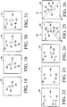
- Figs. 3-14 illustrate forward propagation of polarization components of first and second light beams from the first and second fibers 12 and 14 of Fig. 1.
- Each of the twelve figures is an illustration of the positions of the polarization components at a forward face of one of the twelve components of Fig. 2.
- the optical axis of the first fiber defines a first port 56, i.e., window, at the forward face of the polarization mixer 22 that is defined by the two split elements 18 and 20.
- the orthogonal polarization components 58 and 60 of the first beam are illustrated as thickened black lines in Fig. 3.
- polarization components 62 and 64 of the third beam from the third fiber define a window 66 at the forward face of the split element 18.
- the optical axis of the first beam is aligned with the lower portion 36 of the first split element 18, while the optical axis of the third beam is aligned with the upper portion 32.
- the first polarization component 58 and the third polarization component 62 are shifted to locations 68 and 70 when the forwardly propagating four polarization components 58-64 reach the forward face of the second split element 20, as shown in Fig. 4.
- the second polarization component 60 and the fourth polarization component 64 are in alignment with the walk-off directions of the upper portion 34 and lower portion 38 of the second element within the polarization mixer.
- the polarization mixer that is formed by the two optical elements 18 and 20 combines one of the polarization components 58 from the first port 56 with one of the polarization components 64 from the second port 66, and the remaining two polarization components are also combined.
- the "mixed" polarization components are on the forward propagation paths indicated by shifted locations 68 and 70 in Fig. 5.
- the walk-off operation of the forward element 56 of the polarization combinor shifts the first polarization component 58 back to the position of the window 56 and shifts the third polarization component 62 to a location 72, as shown in Fig. 6.
- Fig. 7 illustrates the four polarization components 58-64 after the second element 28 of the polarization combinor has shifted the second and fourth polarization components 60 and 64.
- the first and second polarization components 58 and 60 that form the input beam from the window 56 are returned to the original position of Fig. 3, but the third and fourth polarization components 62 and 64 that originally formed the beam at window 66 are at locations 72 and 74 on opposite sides of the window 56 and are isolated from each other by a distance greater than the separation between the original windows 56 and 66.
- Fig. 8 illustrates the rotated alignment directions of the four polarization components at original window 56 and at shifted locations 72 and 74.
- the four polarization components are then introduced into the two-stage optical isolator array 30 of Fig. 2.
- the first element 42 of the two-stage optical isolator array 30 is the walk-off crystal having the upwardly directed walk-off direction. This causes the vertically oriented second and fourth polarization components 60 and 64 to shift upwardly to locations 76 and 78 in Fig. 9.
- the thickness of the walk-off crystal 42 is less than the thickness of previously encountered walk-off crystals.
- the thickness of the crystals 26 and 28 may each be approximately 10 ⁇ ⁇ 2 a, while the thickness of the crystal 42 may be approximately 10a, where "a" is one-half of the pitch between the two windows 56 and 66.
- the value of a is 125 ⁇ m, so that the walk-off crystals 26 and 28 are each approximately 1,770 ⁇ m and the thickness of the walk-off crystal 42 is approximately 1,250 ⁇ m.
- the value of a is not critical to the invention.
- the four polarization components 58-64 are rotated 45° by Faraday rotator 44 of Fig. 9 to provide the polarization orientation shown in Fig. 10.
- the walk-off crystal 46 shifts the positions of the first and third polarization components 58 and 62 to locations 80 and 82, respectively. This temporarily places the two polarization components 58 and 60 of the beam that entered at the window 56 in a side-by-side relationship. However, the second walk-off crystal 48 in the pair then shifts the second and fourth polarization components to the locations 84 and 86 shown in Fig. 12.
- the second Faraday rotator 50 rotates the polarization orientations of all four components 58-64, so that the polarization components are oriented as shown in Fig. 13 when the components reach the forward face of the walk-off crystal 52.
- the walk-off direction of the crystal 52 is downward. Consequently, the first and third polarization components 58 and 62 are displaced by a distance determined by the thickness of the crystal 52.
- the third polarization component 62 is shifted to location 88.
- the first polarization component 58 is shifted to the location 84, which corresponds to the optical axis of the second fiber 16 described with reference to Fig. 1.
- the polarization components 58 and 60 that were input from the window 56 defined by the first optical fiber 12 are the output signal for the second optical fiber 16.
- the imaging lens 54 focuses the image onto the second optical fiber.
- the two polarization components 62 and 64 that are input at the window 66 (see Fig. 3) from the third fiber are isolated each other and from output through the second fiber, as shown by the locations 86 and 88 in Fig. 14.
- Figs. 15-26 illustrate rearward propagation from the second optical fiber 16 to the third optical fiber 14.
- the location 84 in Fig. 15 corresponds to the port for input/output signals to and from the second fiber.
- polarization components 90 and 92 are shown as the as the components of an input beam from the second fiber.
- the polarization components of the input beam from the second fiber will be referred to as the fifth and sixth polarization components 90 and 92.
- the imaging lens 54 allows the fifth and sixth polarization components to pass to the rearward face of the walk-off crystal 52 without effect upon orientation or position, as shown in Fig. 16. However, the walk-off crystal 52 shifts the fifth polarization component upwardly to the position 80 shown at the rearward face of the Faraday rotator 50 in Fig. 17.
- the Faraday rotator causes the polarizations to rotate 45° to the alignments shown in Fig. 18 at the rearward face of the walk-off crystal 48.
- the walk-off crystal 48 displaces the sixth polarization component 92 to the position 78 of Fig. 19.
- the other walk-off crystal 46 in the pair then shifts the fifth polarization component 90 to the position 72 as the rearwardly propagating beam components reach the rearward face of the Faraday rotator 44 in Fig. 20.
- the Faraday rotator initiates counterclockwise rotation of the two polarization components 90 and 92 to the orientation shown in Fig. 21 on the rearward face of the walk-off crystal 42.
- the sixth polarization component 92 has been displaced downwardly by operation of the walk-off crystal 42.
- the half-wave plate 40 rotates the two polarization components 90 and 92 to the orientation shown in Fig. 23.
- Fig. 23 shows the interface between the half-wave plate 40 and the polarization combinor 24 of Fig. 2.
- This interface between the polarization combinor and the half-wave plate is also represented in Fig. 7 for the forwardly propagating polarization components. Comparing Fig. 7 with Fig. 23, it can be seen that the third and fourth polarization components of the beam from the third fiber 14 are identical in position and orientation to the fifth and sixth polarization components 90 and 92 of the rearwardly propagating beam from the second fiber 16.
- the final four elements 28, 26, 20 and 18 operate in the inverse to the operations described with reference to Figs. 3-6. Consequently, the rearwardly propagating polarization components 90 and 92 reach the third fiber 14 for output.
- the first walk-off crystal 28 in the polarization combinor pair shifts the sixth polarization component 92 to the position 70 upon reaching the rearward face of the second walk-off crystal 26 in the pair, as shown in Fig. 24.
- the crystal 26 shifts the fifth polarization component 92 to the position 68 in Fig. 25, as the polarization components reach the rearward face of the polarization mixer pair 22 described with reference to Fig. 2.
- the upper portion 34 of the rearward split element 20 has no effect on the fifth polarization component 90, but the lower portion 38 causes the sixth polarization component 92 to be displaced to the window 66 of the third optical fiber, as shown at Fig. 26. While not shown in the drawings, the upper portion 32 of the split elements 18 then shifts the fifth polarization component 90 into alignment with the window 66 for output of the two beam components along the third fiber.
- the assembly 10 optically couples the first fiber 12 to the second fiber 16 and optically couples the second fiber 16 to the third fiber 14, but isolates the fibers from spurious transmissions.
- FIG. 27-30 A similar arrangement is illustrated in Figs. 27-30. Many of the optical elements of the assembly 94 of Fig. 27 are identical to the assembly 10 of Fig. 1. For these elements, the reference numerals have been duplicated. The half-wave plate and all of the elements 42-52 of the two-stage optical assembly 30 are common to the embodiments of Figs. 1 and 27. The difference between the two embodiments is that the polarization mixer 22 and the polarization combinor 24 have been replaced by a pair of split optical members 96 and 98. Each of the split optical members includes a walk-off portion 100 and 102 and an optically neutral portion 104 and 106. The optically neutral portions are aligned with the window 56 at the optical axis of the first fiber 12. On the other hand, the walk-off portions are aligned with the window 66 for the third fiber 14.
- the forward split optical member 96 has a walk-off portion 100 that shifts the third polarization component 62 in the direction indicated by the arrow within portion 100 in Fig. 28. Consequently, the third polarization component is displaced to the location 72 of Fig. 29.
- the optically neutral portion 104 of the first member 96 allows both of the first and second polarization components 58 and 60 to propagate to the forward face of the second member 98 without effect.
- the second of the two optically split members 98 displaces the fourth polarization component 64 in the walk-off direction indicated by the arrow in portion 102 of Fig. 29. Referring to Fig. 30, the fourth polarization component 64 is displaced to the location 74 when the beam component reaches the forward face of the half-wave plate 40.
- the four polarization components 58-64 are in identical positions when the beam components reach the forward face of the half-wave plate 40. Consequently, the remaining optical elements 40-54 in the assembly 94 of Fig. 27 will have the identical optical effects described with reference to Figs. 7-14. Rearwardly propagating light from the second fiber 16 of Fig. 27 will likewise be affected by the components 40-54 in the same manner as described with reference to Figs. 15-22. Therefore, the fifth and sixth polarization components from the second fiber 16 will reach the rearward face of the split optical member 98 in the same positions 72 and 74 and orientations shown in Fig. 23.
- the walk-off portions 100 and 102 of the split optical members 96 and 98 displace the rearwardly propagating fifth and sixth polarization components in a manner that is the inverse of the forwardly propagating third and fourth polarization components 62 and 64 in Figs. 28-30. It follows that the rearwardly propagating fifth and sixth components are optically coupled to the third fiber 14.
- the assembly 10 of Fig. 1 is preferred.
- the assembly 94 is more susceptible to scattering at the interfaces between the two split optical elements 96 and 98 and between the rearward split optical element 98 and the half-wave plate. This greater concern for interface scattering is a result of the greater thickness of each of the split optical members 96 and 98 relative to the thicknesses of the split elements 18 and 20 of Fig. 1.
- FIG. 31 A third embodiment is shown in Fig. 31.
- the optical assembly 108 of Fig. 31 is identical to the assembly 10 of Figs. 1 and 2, with the exceptions that the polarization combinor 24 has been eliminated and the walk-off crystal 42 of assembly 10 has been replaced with a walk-off crystal 110 having an oppositely directly walk-off displacement. Since all of the other elements of assembly 108 have the same functions and relative positions described with reference to Figs. 1 and 2, the reference numerals have been duplicated.
- the assembly 108 of Fig. 31 requires placement of the optical axis of the second fiber 16 at a level below the optical axes of the first and third fibers 12 and 14. That is, the input/output port at the rearward end of the assembly 108 is at a level below the input/output ports at the forward end of the assembly.
- the polarization mixer that is comprised of the split element 18 and 20 functions in the same manner as described with reference to Figs. 3 and 4.
- the polarization components of an input beam from the first fiber will reach the forward face of the half-wave plate 40 in the positions and orientations shown in Fig. 5.
- All four of the polarization components 58, 60, 62 and 64 are then rotated 45° upon reaching the forward face of the walk-off crystal 110.
- the walk-off crystal 110 displaces the second and fourth polarization components downwardly.
- the four polarization components are aligned as shown in Fig. 9, but each component is diagonally shifted downwardly and to the right. That is, the second polarization component 60 is centered between the two windows 56 and 66, with the third polarization component 62 immediately above this position and the first polarization component 58 immediately below this position.
- the fourth polarization component 64 is positioned immediately below the first polarization component, so that all four components are spaced apart along a vertical plane between the two windows 56 and 66.
- the optical elements 44, 46, 48, 50, 52 and 54 operate identically to the manner described with reference to Figs. 9-14. Consequently, the four polarization components 58-64 reach the forward face of the imaging lens 54 diagonally shifted downwardly and to the right relative to the position shown in Fig. 14.
- the input/output window for the second fiber is immediately below the window 66.
- the optical assembly 108 of Fig. 31 operates well for its intended purpose, but the absence of the polarization combinor 24 of Figs. 1 and 2 increases the angular sensitivity of the half-wave plate 40. For this reason, the optical assembly 10 of Figs. 1 and 2 is preferred.
- the preferred embodiment also utilizes TEC fibers.
- a preferred method of property aligning the TEC fibers 12 and 14 is shown in Figs. 32 and 33.
- a semiconductor substrate such as a silicon wafer 112 is etched to form V-shaped grooves 114 and 116.
- Conventional integrated circuit fabrication techniques may be utilized.
- the grooves may be formed photolithographically, using a mask to define the grooves and using a chemical etchant.
- the angle of one wall of a groove relative to the other is preferably 70.5°.
- TEC fiber cores without conventional coating material are then placed in the grooves.
- the silicon processing enables a precise center-to-center spacing of the fiber cores. Tolerances of less than 1 micron are achieved.
- a second silicon wafer 118 having a corresponding array of V-shaped grooves is fixed to the lower silicon wafer 112 by a layer of adhesive, not shown.
- the use of adhesive is not critical.
- wafer bonding may be used to attach the two silicon wafers.
- Silicon V-shaped alignment of single-mode fibers and multi-mode fibers is known in the art, and assemblies of the type shown in Fig. 33 are commercially available.
Abstract
Description
- The invention relates generally to optical assemblies and methods for selectively coupling ports for transmission of signals and more particularly to assemblies and methods for achieving optical circulation and isolation in multi-port systems.
- The flexibility and reliability of communication networks based upon transmissions of light signals via optical fibers are greatly increased by the availability of assemblies such as optical circulators and isolators. For example, a three-port circulator may be used to enable a single fiber to be used for bidirectional communications between two remote sites. By utilizing non-reciprocal optical elements, i.e. elements which affect light moving in different directions differently, a bidirectional fiber may be optically coupled to both an input fiber and an output fiber. Non-reciprocal operations provide differences in the "walk-off," i.e. spatial displacement, of oppositely directed light beams, so that the input and output fibers are optically isolated from each other.
- An optical isolator may include only single-mode fibers. The input fiber directs light signals into an optical assembly that splits the light into polarization components, performs non-reciprocal operations on the components, and recombines the components for output at the output fiber. The non-reciprocal operations are designed to reduce the likelihood that back-directed light will be aligned with the input fiber.
- U.S. Pat. No. 4,464,022 to Emkey describes an optical circulator that includes a first birefringent plate that is used to separate a beam from a first port into two beams having orthogonal polarizations. The two beams are then recombined by a second birefringent plate positioned at a second port. Between the first and second birefringent plates is a Faraday rotator that provides non-reciprocal rotation of the polarizations. A third birefringent plate and a reflecting element are positioned between the third and second birefringent plates, so that the beams are reflected at a ninety degree angle to the second port. However, the reflecting element has a slotted portion that allows light from a third port to pass through the reflecting element toward the first port. Thus, the first port acts as an input port for transmission of signals via the second port, but acts as an output port for signals from the third port. The ninety degree angle of the second port relative to the first and third ports is designed to maximize the isolation of the second port from the third port. A similar arrangement is described in U.S. Pat. No. 5,212,586 to Van Delden.
- There are a number of factors that must be considered in the design of optical circulators and isolators. U.S. Pat. No. 5,319,483 to Krasinski et al. identifies insertion loss and crosstalk as two performance-related design considerations. Insertion loss is the difference in power between input light and the light that exits the optical assembly. The primary causes of insertion loss are identified as absorption of light and imperfections of polarization separation and recombination. Crosstalk in an optical circulator is the transmission of light from an input fiber to a fiber which is not the intended output fiber. Krasinski et al. assert that the primary cause of crosstalk in optical circulators is back-reflection from the various optical elements in the assembly. The system described in the patent utilizes birefringent crystals instead of polarization reflecting elements and polarization splitting cubes in an attempt to provide more complete polarization separation, thereby reducing insertion loss and crosstalk. Moreover, the system is one in which the optical circulators of the assembly are in optical contact with each other, thereby reducing back-reflections.
- While known optical circulators and isolators operate well for their intended purposes, further improvements in performance are desired. Another design goal is to increase cost efficiency in the fabrication of optical circulators and isolators.
- What is needed is an optical assembly and method for efficiently transferring optical signals within a multi-port system, such that each port is selectively coupled with respect to exchanges of signals among the remaining ports. What is also needed is such an optical assembly that is fabricated cost efficiently.
- An optical assembly, preferably an optical circulator, includes first and third input/output ports at a forward end of the assembly and a second port at a rearward end. A first functionally related group of optical elements is located adjacent to the first and third ports to establish a desired orientation for polarization components of parallel first and third light beams that are respectively introduced via the first and third ports. In the preferred embodiment, the desired orientation is one in which the orthogonal polarization components of the third beam are shifted to locations on opposite sides of the polarization components of the first beam. A second functionally related group of optical elements further isolates the polarization components of the third beam from the propagation of the first beam, which is output via the second port. Reverse propagation of a second beam from the second port directs the second beam to the third port in isolation from the first port. The operation of the first group of optical elements allows an optical isolator (i.e. the second group) to be converted to a cost effective, high performance optical circulator.
- In one embodiment, the first group of optical elements includes a polarization mixer that divides the two orthogonal polarization components of the first beam and divides the two orthogonal polarization components of the third beam, and establishes two forward propagation paths in which one polarization component of the first beam is combined with a polarization component of the third beam. This "mixing" of the polarization components is preferably followed by a polarization combinor that re-merges the polarization components of the first beam, but with the two polarization components of the third beam on opposed sides of the recombined first beam. This provides the desired orientation of polarization components for input to the second group of optical elements. The second group of optical elements may be a half-wave plate followed by a two-stage isolator array, but this is not critical.
- In another embodiment, the desired orientation of polarization components for propagation into the second group of optical elements is achieved using a first group that comprises forward and rearward split optical members. Each split member includes an optically neutral portion aligned with the optical axis of the first port and includes a walk-off portion that is aligned at the optical axis of the third port. The walk-off portions have perpendicular walk-off directions that displace the two orthogonal polarization components of the third beam to opposite sides of the forward propagating first beam. In this embodiment, the second group of optical elements may be a half-wave plate followed by a two-stage isolator array. However, other arrays that propagate the first beam for output via the second port may be substituted.
- In the rearward propagation direction, light is introduced to the second group of optical elements via the second port. The two polarization components of this rearwardly propagating beam are divided by the second optical group and are introduced to the first optical group in the same positions as forwardly propagating polarization components if a beam were introduced from the third port. That is, the spatial displacements of the polarization components of the third beam by operation of the first optical group defines shifted locations of the polarization components, and these shifted locations are coincident with the locations of the polarization components from the rearwardly propagating beam of the second port. The operation of the first optical group on the rearwardly propagating components is the reverse of the operation on the components of the third beam. Consequently, the rearwardly propagating components are recombined for output via the third port.
- In the preferred embodiment, the forwardly propagating light from the first beam is focused onto the second port, thereby increasing transfer efficiency. Also in the preferred embodiment, each of the three ports is associated with a thermally expanded core optical fiber, but other input media may be utilized, including standard optical fibers with a microlens assembly.
- In the embodiment in which the first optical group includes a polarization mixer, the polarization combinor is not a critical feature. However, the performance of the invention is significantly increased if the polarization combinor is used to establish the "desired orientation" of polarization components, as identified previously. This desired orientation provides a preliminary separation of the first and third beams, so that the isolation can be enhanced at the second optical group. Thus, a high performance optical assembly is achieved.
-
- Fig. 1 is a perspective view of one embodiment of an optical assembly for selectively coupling three ports in accordance with the invention.
- Fig. 2 is a perspective exploded view of the optical assembly of Fig. 1.
- Figs. 3-14 illustrate the operations performed upon polarization components during forward propagation through the assembly of Figs. 1 and 2.
- Figs. 15-26 illustrate operations performed upon polarization components during rearward propagation through the assembly of Figs. 1 and 2.
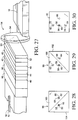
- Fig. 27 is a perspective view of a second embodiment of an optical assembly in accordance with the invention.
- Figs. 28-30 illustrate the operations of the first two components of Fig. 27.
- Fig. 31 is a perspective exploded view of a third embodiment of an optical assembly in accordance with the invention.
- Fig. 32 is an end view of a silicon substrate to sandwich TEC fibers into precisely defined positions.
- Fig. 33 is a partial perspective view of the silicon wafer of Fig. 32 having a second silicon substrate to fix the TEC fibers into position.
-
- With reference to Figs. 1 and 2, an
optical assembly 10 is shown as having parallel first and thirdoptical fibers optical fiber 16 at a rearward end. In the embodiment of Fig. 1, the assembly is an optical circulator in which an input beam from thefirst fiber 12 propagates through the various optical elements for output via thesecond fiber 16, while an input signal from the second fiber is output via thethird fiber 14. However, all other possibilities of optical coupling among the fibers are blocked by operations of the various elements on the polarization components of the beams from the fibers. - In the embodiment of Figs. 1 and 2, the first two
optical elements assembly 10 form apolarization mixer 22. As will be described more fully below with reference to Figs. 3-14, forward propagation of light beams from the first andthird fibers polarization mixer 22 results in two light beams in which each has one polarization component from the beam offiber 16 and one polarization component from the beam offiber 14. This "mixing" of polarization components sets the stage for apolarization combinor 24 formed by the third and fourthoptical elements assembly 10. The polarization combinor re-merges the two polarization components of the first beam from thefirst fiber 12 and shifts the two polarization components of the third beam from thethird fiber 14 to opposite sides of the re-merged first beam. In turn, this arrangement of the polarization components sets the desired orientation for a two-stageoptical isolator array 30 that will be described more fully below. The elements of theassembly 10 combine to form a high performance, cost efficient optical circulator. - As best seen in Fig. 2, the
elements polarization mixer 22 are diagonally divided intoupper portions lower portions lower portions first element 18 is perpendicular to the interface of the upper andlower portions second element 20. Each of the four portions is formed of a walk-off crystal, and the two portions of each of the two elements have oppositely directed walk-off directions. The walk-off directions are indicated by arrows on the four portions 32-38 in Fig. 2. - The two
elements polarization combinor 24 are also formed of walk-off crystal. The walk-off directions are perpendicular to each other, but are directed to the same lateral surface of theassembly 10. As is well known in the art, common materials for forming walk-off crystals are rutile (titanium dioxide-TiO2) and yttrium vanadate (YVO4). The preferred material is rutile, since it provides a greater refractive index. For each one mm of walk-off separation, the rutile crystal must have a thickness of approximately 10 mm. In the embodiment of Figs. 1 and 2, if the core-to-core pitch of the first andthird fibers 2 times one-half the pitch. Therefore, the thickness of each of theelements 2 125 µm = 177 µm. - The
optical element 40 that is at the rearward face of the walk-offcrystal 28 is a half-wave plate that provides polarization rotation. The optical axis of the half-wave plate is 22.5 degrees to the vertical, so that rotation of the polarization states is 45 degrees. Half-wave plates are well known in the art. - As previously noted, the following optical elements provide a two-
stage isolator array 30. Afirst element 42 in the array is a walk-off element which may have a thickness to provide a spatial displacement of 125 µm, but this walk-off distance is not critical to the invention. The walk-off direction is upward, as shown by the arrow in Fig. 2. - The two-stage
optical isolator array 30 includes twoFaraday rotators crystals crystals assembly 10, as viewed in Figs. 1 and 2. Thelast element 52 of the two-stage isolator array 30 is a walk-off crystal having a walk-off direction that is downward and a walk-off distance of 125 µm. The thickness will depend upon the desired walk-off distance, as previously noted. - The two-stage
optical isolator array 30 is followed by animaging lens 54 that is used to focus the output beam from thefirst fiber 12 onto thesecond fiber 16 that is to output the beam. If all of thefibers lens 54 is a one-to-one imaging lens. However, in an embodiment in which thefirst fiber 12 is a TEC fiber and thesecond fiber 16 is a conventional single-mode fiber, the lens may be a four-to-one imaging lens. The lens reconverges the polarization components of the first beam from thefirst fiber 12, which diverge as they pass through theoptical assembly 10. The focal length of the lens is selected based upon forming an image of the first beam onto thesecond fiber 16. - Figs. 3-14 illustrate forward propagation of polarization components of first and second light beams from the first and
second fibers first port 56, i.e., window, at the forward face of thepolarization mixer 22 that is defined by the two splitelements orthogonal polarization components polarization components window 66 at the forward face of thesplit element 18. - The optical axis of the first beam is aligned with the
lower portion 36 of thefirst split element 18, while the optical axis of the third beam is aligned with theupper portion 32. As a result of the walk-off operations of the upper and lower portions (the walk-off directions are shown by arrows in Fig. 3), thefirst polarization component 58 and thethird polarization component 62 are shifted tolocations second split element 20, as shown in Fig. 4. Thesecond polarization component 60 and thefourth polarization component 64 are in alignment with the walk-off directions of theupper portion 34 andlower portion 38 of the second element within the polarization mixer. Consequently, the walk-off operations of the twoportions locations crystal 26 that is the first block of the pair of walk-off crystals that forms the polarization combinor described above. The orientation is shown in Fig. 5. - Comparing Figs. 3 and 5, the polarization mixer that is formed by the two
optical elements polarization components 58 from thefirst port 56 with one of thepolarization components 64 from thesecond port 66, and the remaining two polarization components are also combined. The "mixed" polarization components are on the forward propagation paths indicated by shiftedlocations - The walk-off operation of the
forward element 56 of the polarization combinor shifts thefirst polarization component 58 back to the position of thewindow 56 and shifts thethird polarization component 62 to alocation 72, as shown in Fig. 6. - Fig. 7 illustrates the four polarization components 58-64 after the
second element 28 of the polarization combinor has shifted the second andfourth polarization components second polarization components window 56 are returned to the original position of Fig. 3, but the third andfourth polarization components window 66 are atlocations window 56 and are isolated from each other by a distance greater than the separation between theoriginal windows - The four polarization components 58-64 are rotated in place by operation of the half-
wave plate 40. The use of half-wave plates is well known in the art. Fig. 8 illustrates the rotated alignment directions of the four polarization components atoriginal window 56 and at shiftedlocations optical isolator array 30 of Fig. 2. - The
first element 42 of the two-stageoptical isolator array 30 is the walk-off crystal having the upwardly directed walk-off direction. This causes the vertically oriented second andfourth polarization components locations crystal 42 is less than the thickness of previously encountered walk-off crystals. For example, the thickness of thecrystals 2 a, while the thickness of thecrystal 42 may be approximately 10a, where "a" is one-half of the pitch between the twowindows crystals crystal 42 is approximately 1,250 µm. However, the value of a is not critical to the invention. - The four polarization components 58-64 are rotated 45° by
Faraday rotator 44 of Fig. 9 to provide the polarization orientation shown in Fig. 10. The walk-offcrystal 46 shifts the positions of the first andthird polarization components locations 80 and 82, respectively. This temporarily places the twopolarization components window 56 in a side-by-side relationship. However, the second walk-offcrystal 48 in the pair then shifts the second and fourth polarization components to thelocations - The
second Faraday rotator 50 rotates the polarization orientations of all four components 58-64, so that the polarization components are oriented as shown in Fig. 13 when the components reach the forward face of the walk-offcrystal 52. The walk-off direction of thecrystal 52 is downward. Consequently, the first andthird polarization components crystal 52. For a rutile crystal having a thickness of approximately 1,250 µm, the downward shift is equal to approximately a = 125 µm. Thethird polarization component 62 is shifted tolocation 88. Thefirst polarization component 58 is shifted to thelocation 84, which corresponds to the optical axis of thesecond fiber 16 described with reference to Fig. 1. Thus, thepolarization components window 56 defined by the first optical fiber 12 (see Fig. 3) are the output signal for the secondoptical fiber 16. Theimaging lens 54 focuses the image onto the second optical fiber. On the other hand, the twopolarization components locations - Figs. 15-26 illustrate rearward propagation from the second
optical fiber 16 to the thirdoptical fiber 14. As previously noted, thelocation 84 in Fig. 15 corresponds to the port for input/output signals to and from the second fiber. In Fig. 15,polarization components sixth polarization components - The
imaging lens 54 allows the fifth and sixth polarization components to pass to the rearward face of the walk-offcrystal 52 without effect upon orientation or position, as shown in Fig. 16. However, the walk-offcrystal 52 shifts the fifth polarization component upwardly to theposition 80 shown at the rearward face of theFaraday rotator 50 in Fig. 17. The Faraday rotator causes the polarizations to rotate 45° to the alignments shown in Fig. 18 at the rearward face of the walk-offcrystal 48. - The walk-off
crystal 48 displaces thesixth polarization component 92 to theposition 78 of Fig. 19. The other walk-offcrystal 46 in the pair then shifts thefifth polarization component 90 to theposition 72 as the rearwardly propagating beam components reach the rearward face of theFaraday rotator 44 in Fig. 20. The Faraday rotator initiates counterclockwise rotation of the twopolarization components crystal 42. - In Fig. 22, the
sixth polarization component 92 has been displaced downwardly by operation of the walk-offcrystal 42. The half-wave plate 40 rotates the twopolarization components wave plate 40 and thepolarization combinor 24 of Fig. 2. This interface between the polarization combinor and the half-wave plate is also represented in Fig. 7 for the forwardly propagating polarization components. Comparing Fig. 7 with Fig. 23, it can be seen that the third and fourth polarization components of the beam from thethird fiber 14 are identical in position and orientation to the fifth andsixth polarization components second fiber 16. As will be explained immediately below, the final fourelements polarization components third fiber 14 for output. - The first walk-off
crystal 28 in the polarization combinor pair shifts thesixth polarization component 92 to theposition 70 upon reaching the rearward face of the second walk-offcrystal 26 in the pair, as shown in Fig. 24. Thecrystal 26 shifts thefifth polarization component 92 to theposition 68 in Fig. 25, as the polarization components reach the rearward face of thepolarization mixer pair 22 described with reference to Fig. 2. - The
upper portion 34 of therearward split element 20 has no effect on thefifth polarization component 90, but thelower portion 38 causes thesixth polarization component 92 to be displaced to thewindow 66 of the third optical fiber, as shown at Fig. 26. While not shown in the drawings, theupper portion 32 of thesplit elements 18 then shifts thefifth polarization component 90 into alignment with thewindow 66 for output of the two beam components along the third fiber. - Referring to Figs. 1-26, the
assembly 10 optically couples thefirst fiber 12 to thesecond fiber 16 and optically couples thesecond fiber 16 to thethird fiber 14, but isolates the fibers from spurious transmissions. - A similar arrangement is illustrated in Figs. 27-30. Many of the optical elements of the
assembly 94 of Fig. 27 are identical to theassembly 10 of Fig. 1. For these elements, the reference numerals have been duplicated. The half-wave plate and all of the elements 42-52 of the two-stageoptical assembly 30 are common to the embodiments of Figs. 1 and 27. The difference between the two embodiments is that thepolarization mixer 22 and thepolarization combinor 24 have been replaced by a pair of splitoptical members portion neutral portion window 56 at the optical axis of thefirst fiber 12. On the other hand, the walk-off portions are aligned with thewindow 66 for thethird fiber 14. - The forward split
optical member 96 has a walk-offportion 100 that shifts thethird polarization component 62 in the direction indicated by the arrow withinportion 100 in Fig. 28. Consequently, the third polarization component is displaced to thelocation 72 of Fig. 29. However, the opticallyneutral portion 104 of thefirst member 96 allows both of the first andsecond polarization components second member 98 without effect. The second of the two optically splitmembers 98 displaces thefourth polarization component 64 in the walk-off direction indicated by the arrow inportion 102 of Fig. 29. Referring to Fig. 30, thefourth polarization component 64 is displaced to thelocation 74 when the beam component reaches the forward face of the half-wave plate 40. - Comparing Figs. 7 and 30, the four polarization components 58-64 are in identical positions when the beam components reach the forward face of the half-
wave plate 40. Consequently, the remaining optical elements 40-54 in theassembly 94 of Fig. 27 will have the identical optical effects described with reference to Figs. 7-14. Rearwardly propagating light from thesecond fiber 16 of Fig. 27 will likewise be affected by the components 40-54 in the same manner as described with reference to Figs. 15-22. Therefore, the fifth and sixth polarization components from thesecond fiber 16 will reach the rearward face of the splitoptical member 98 in thesame positions portions optical members fourth polarization components third fiber 14. - The thickness of each of the split
optical members optical members input fiber 12 to the optical axis of anoutput fiber 16, the thickness of each of theelements 2 a. If the core-to-core pitch of thefibers second fiber 16 is centered between the two axes of thefibers elements 2 125 µm = 177 µm. In comparison, each of the walk-offportions optical elements 2 a = 353.5 µm. - While the
optical assembly 94 of Fig. 27 operates well for its intended purpose, theassembly 10 of Fig. 1 is preferred. Theassembly 94 is more susceptible to scattering at the interfaces between the two splitoptical elements optical element 98 and the half-wave plate. This greater concern for interface scattering is a result of the greater thickness of each of the splitoptical members split elements - A third embodiment is shown in Fig. 31. The
optical assembly 108 of Fig. 31 is identical to theassembly 10 of Figs. 1 and 2, with the exceptions that thepolarization combinor 24 has been eliminated and the walk-offcrystal 42 ofassembly 10 has been replaced with a walk-offcrystal 110 having an oppositely directly walk-off displacement. Since all of the other elements ofassembly 108 have the same functions and relative positions described with reference to Figs. 1 and 2, the reference numerals have been duplicated. In addition to the elimination of the polarization combinor and the reversed walk-off direction ofcrystal 110, theassembly 108 of Fig. 31 requires placement of the optical axis of thesecond fiber 16 at a level below the optical axes of the first andthird fibers assembly 108 is at a level below the input/output ports at the forward end of the assembly. - The polarization mixer that is comprised of the
split element wave plate 40 in the positions and orientations shown in Fig. 5. All four of thepolarization components crystal 110. - The walk-off
crystal 110 displaces the second and fourth polarization components downwardly. At the forward face of theFaraday rotator 44, the four polarization components are aligned as shown in Fig. 9, but each component is diagonally shifted downwardly and to the right. That is, thesecond polarization component 60 is centered between the twowindows third polarization component 62 immediately above this position and thefirst polarization component 58 immediately below this position. Thefourth polarization component 64 is positioned immediately below the first polarization component, so that all four components are spaced apart along a vertical plane between the twowindows - The
optical elements imaging lens 54 diagonally shifted downwardly and to the right relative to the position shown in Fig. 14. The input/output window for the second fiber is immediately below thewindow 66. - The
optical assembly 108 of Fig. 31 operates well for its intended purpose, but the absence of thepolarization combinor 24 of Figs. 1 and 2 increases the angular sensitivity of the half-wave plate 40. For this reason, theoptical assembly 10 of Figs. 1 and 2 is preferred. - While not critical, the preferred embodiment also utilizes TEC fibers. A preferred method of property aligning the
TEC fibers silicon wafer 112, is etched to form V-shapedgrooves - In Fig. 33, a
second silicon wafer 118 having a corresponding array of V-shaped grooves is fixed to thelower silicon wafer 112 by a layer of adhesive, not shown. The use of adhesive is not critical. Alternatively, wafer bonding may be used to attach the two silicon wafers. Silicon V-shaped alignment of single-mode fibers and multi-mode fibers is known in the art, and assemblies of the type shown in Fig. 33 are commercially available.
Claims (10)
- An optical assembly (10; 94; and 108) for selectively coupling ports that include a first port (12) and a third port (14) at a forward end of said optical assembly and a second port (16) at a rearward end opposite to said forward end, said optical assembly comprising:a polarization mixer (22) for establishing propagation paths for orthogonal polarization components (58, 60, 62 and 64) of beams introduced from said first and third ports such that forward propagation paths of first and second orthogonal polarization components of said beam from said first port are spaced apart while being respectively coincident with spaced-apart forward propagation paths of third and fourth orthogonal polarization components of said beam from said third port; andan array of optical elements (30) having a forward face positioned adjacent to said polarization mixer such that said forward propagation paths are incident to said forward face, said array including at least two walk-off elements (42, 46, 48 and 52) which are dependent upon polarization directions of said polarization components, said array having combined walk-off properties for said first, second, third, and fourth polarization components to align said first and second polarization components with said second port.
- The optical assembly (10) of claim 1 wherein said array (30) of optical elements includes a polarization combinor (24) at said forward face of said array for shifting forward propagation paths of said polarization components such that shifted forward propagation paths of said first and second polarization components (58 and 60) are coincident and are spaced apart from shifted forward propagation paths of said third and fourth polarization components (62 and 64), said polarization combinor being a pair of walk-off elements (26 and 28).
- The optical assembly (10; 108) of claim 1 or 2 wherein said array (30) of optical elements has walk-off properties with respect to a rearward beam introduced from said second port (16) such that orthogonal fifth and sixth polarization components (90 and 92) of said rearward beam are separated and reach said polarization mixer (22) with each of said fifth and sixth polarization components aligned with said forward propagation path of a third and fourth polarization component (62 and 64) having a corresponding polarization orientation, said array of optical elements and said polarization mixer (22) thereby forming an optical circulator for which said first port (12) is optically coupled to said second port (16) and for which said second port is optically coupled to said third port (14).
- The optical assembly of claim 1, 2 or 3 further comprising an imaging lens (54) positioned to focus said first and second polarization components (58 and 60) onto said second port (16).
- The optical assembly (10; 108) of claim 1, 2, 3 or 4 wherein said polarization mixer (22) includes forward and rearward split walk-off members (18 and 20), each of said split walk-off members having first and second portions (32, 34, 36 and 38) with opposed walk-off directions, said walk-off directions of said forward split walk-off element being perpendicular to said walk-off directions of said rearward split walk-off member.
- The optical assembly (10; 108) of claim 1, 2, 3, 4 or 5 wherein said array (30) of optical elements includes at least two Faraday rotators (44 and 50), said array being a two-stage optical isolator.
- The optical assembly (10; 108) of claim 1, 2, 3, 4, 5 or 6 wherein each of said first, second, and third ports (12, 14 and 16) is associated with a thermally expanded core (TEC) fiber.
- A method of transferring optical signals from a first fiber (12) to a second fiber (16) and from said second fiber to a third fiber (14) to form an optical circulator (10; 94; 108) comprising steps of:(a) positioning said first and third fibers in a side-by-side parallel relationship and in a direction opposite to said second fiber;(b) performing first operations on first and third light beams respectively directed from said first and third fibers, including executing substeps comprising:(b1) spatially displacing orthogonal third and fourth polarization components (62 and 64) of said third beam such that said third and fourth polarization components are located at shifted locations (72 and 74) that are spaced apart by a first distance; and(b2) propagating orthogonal first and second polarization components (58 and 60) of said first beam such that said first and second polarization components are coincident and are located between said third and fourth polarization components in a common plane with said shifted locations;(c) performing second operations on said first, second, third and fourth polarization components following said first operations, including executing substeps comprising:(c1) aligning said first and second polarization components for output via said second fiber;(c2) spatially shifting said third and fourth polarization components such that each is spaced apart from said first and second polarization components by a distance at least as great as said first distance;(c3) spatially displacing fifth and sixth polarization components (90 and 92) of a second light beam introduced via said second fiber such that said fifth and sixth components respectively propagate to said shifted locations; and(d) merging said fifth and sixth polarization components from said shifted locations to said third fiber for output via said third fiber.
- The method of claim 8 wherein said step (b) of performing said first operations includes providing a polarization mixer (22) and a polarization combinor (24) such that said polarization mixer merges said first polarization component (58) with said third polarization component (62) and mixes said second polarization component (60) with said fourth polarization component (64), while said polarization combinor establishes the relationships set forth in substeps (b1) and (b2).
- The method of claim 8 wherein said step (b) of performing said first operations includes providing forward and rearward split members (96 and 98), with substep (b1) being implemented by walking-off said third polarization component (62) to one side of an optical axis (56) of said first fiber (12) and walking-off said fourth polarization component (64) to an opposite side of said optical axis, said substep (b2) being implemented by propagating said first and second polarization components (58 and 60) through said forward and rearward split members along said optical axis.
Applications Claiming Priority (2)
| Application Number | Priority Date | Filing Date | Title |
|---|---|---|---|
| US08/923,014 US6011649A (en) | 1997-09-03 | 1997-09-03 | Optical assembly and method for high performance coupling |
| US923014 | 1997-09-03 |
Publications (2)
| Publication Number | Publication Date |
|---|---|
| EP0903611A1 true EP0903611A1 (en) | 1999-03-24 |
| EP0903611B1 EP0903611B1 (en) | 2002-10-16 |
Family
ID=25447972
Family Applications (1)
| Application Number | Title | Priority Date | Filing Date |
|---|---|---|---|
| EP98112736A Expired - Lifetime EP0903611B1 (en) | 1997-09-03 | 1998-07-09 | Optical assembly and method for high performance coupling |
Country Status (4)
| Country | Link |
|---|---|
| US (1) | US6011649A (en) |
| EP (1) | EP0903611B1 (en) |
| JP (1) | JPH11316317A (en) |
| DE (1) | DE69808713T2 (en) |
Families Citing this family (6)
| Publication number | Priority date | Publication date | Assignee | Title |
|---|---|---|---|---|
| US6049426A (en) | 1998-08-17 | 2000-04-11 | New Focus, Inc. | Compact polarization insensitive circulators with simplified structure and low polarization mode dispersion |
| US6175448B1 (en) | 1998-08-17 | 2001-01-16 | New Focus, Inc. | Optical circulators using beam angle turners |
| US6212008B1 (en) * | 1998-11-13 | 2001-04-03 | New Focus, Inc. | Compact polarization insensitive circulators with simplified structure and low polarization mode dispersion |
| US6301045B1 (en) * | 1999-01-27 | 2001-10-09 | Alliance Fiber Optics Products, Inc. | Three-port optical circulator |
| US6822793B2 (en) | 1999-10-29 | 2004-11-23 | Finisar Corporation | Compact polarization insensitive circulators with simplified structure and low polarization mode dispersion |
| US6404955B1 (en) | 2001-07-03 | 2002-06-11 | Corning, Incorporated | System and method for fabricating arrayed optical fiber collimators |
Citations (5)
| Publication number | Priority date | Publication date | Assignee | Title |
|---|---|---|---|---|
| EP0491607A2 (en) * | 1990-12-17 | 1992-06-24 | Nippon Telegraph And Telephone Corporation | Optical circulator |
| WO1994009400A1 (en) * | 1992-10-20 | 1994-04-28 | Telstra Corporation Limited | An optical circulator |
| US5574596A (en) * | 1995-05-01 | 1996-11-12 | Jds Fitel Inc. | Optical circulator |
| US5734763A (en) * | 1996-09-04 | 1998-03-31 | Hewlett-Packard Company | Compact two-by-n optical components based on bierfringent walk-off crystals |
| EP0860731A1 (en) * | 1997-02-25 | 1998-08-26 | Hewlett-Packard Company | Compact, low crosstalk, three-port optical circulator |
Family Cites Families (6)
| Publication number | Priority date | Publication date | Assignee | Title |
|---|---|---|---|---|
| US4464022A (en) * | 1982-09-28 | 1984-08-07 | At&T Bell Laboratories | Optical circulator |
| US5212586A (en) * | 1991-11-26 | 1993-05-18 | Optics For Research | Optical circulator having a simplified construction |
| US5319483A (en) * | 1992-12-04 | 1994-06-07 | Williams Telecommunications Group, Inc. | Polarization independent low cross-talk optical circulator |
| WO1994015243A1 (en) * | 1992-12-22 | 1994-07-07 | Telstra Corporation Limited | An optical isolator |
| AU1379095A (en) * | 1993-12-10 | 1995-06-27 | Jds Fitel Inc. | Optical non-reciprocal devices |
| US5471340A (en) * | 1994-01-07 | 1995-11-28 | Jds Fitel Inc. | Reflective optical non-reciprocal devices |
-
1997
- 1997-09-03 US US08/923,014 patent/US6011649A/en not_active Expired - Fee Related
-
1998
- 1998-07-09 DE DE69808713T patent/DE69808713T2/en not_active Expired - Fee Related
- 1998-07-09 EP EP98112736A patent/EP0903611B1/en not_active Expired - Lifetime
- 1998-09-02 JP JP10264007A patent/JPH11316317A/en not_active Withdrawn
Patent Citations (5)
| Publication number | Priority date | Publication date | Assignee | Title |
|---|---|---|---|---|
| EP0491607A2 (en) * | 1990-12-17 | 1992-06-24 | Nippon Telegraph And Telephone Corporation | Optical circulator |
| WO1994009400A1 (en) * | 1992-10-20 | 1994-04-28 | Telstra Corporation Limited | An optical circulator |
| US5574596A (en) * | 1995-05-01 | 1996-11-12 | Jds Fitel Inc. | Optical circulator |
| US5734763A (en) * | 1996-09-04 | 1998-03-31 | Hewlett-Packard Company | Compact two-by-n optical components based on bierfringent walk-off crystals |
| EP0860731A1 (en) * | 1997-02-25 | 1998-08-26 | Hewlett-Packard Company | Compact, low crosstalk, three-port optical circulator |
Also Published As
| Publication number | Publication date |
|---|---|
| US6011649A (en) | 2000-01-04 |
| JPH11316317A (en) | 1999-11-16 |
| EP0903611B1 (en) | 2002-10-16 |
| DE69808713T2 (en) | 2003-08-14 |
| DE69808713D1 (en) | 2002-11-21 |
Similar Documents
| Publication | Publication Date | Title |
|---|---|---|
| EP0965867B1 (en) | Multi-port optical circulator utilizing imaging lens and correction optical element | |
| US5446578A (en) | Polarization preserving optical isolator | |
| US5706371A (en) | Optical isolator array device | |
| US6590706B1 (en) | Optical circulators using beam angle turners | |
| AU740363B2 (en) | Method of aligning optical fibers to a multi-port optical assembly | |
| US6249619B1 (en) | Optical isolator | |
| EP0898185B1 (en) | Optical assembly and method based on tec fibers | |
| EP1726983B1 (en) | Optical device comprising an optical isolator | |
| US6263131B1 (en) | Reflective non-reciprocal optical device | |
| CA2586683A1 (en) | Multi-stage optical isolator | |
| US6075642A (en) | Multi-port optical isolator | |
| US6026202A (en) | Compact, low crosstalk, three-port optical circulator | |
| EP0903611B1 (en) | Optical assembly and method for high performance coupling | |
| US6246807B1 (en) | Optical circulator | |
| US7826137B2 (en) | Reflective optical circulator | |
| US6043933A (en) | Split optical element and a low cost fabrication approach | |
| AU748150B2 (en) | Polarization mixer based on walk-off crystals, half-wave plates and tec fibers | |
| JPH08194130A (en) | Optical connector | |
| JPH0627415A (en) | 3-port type optical circulator | |
| JPH0627414A (en) | 3-port type optical circulator | |
| JPH09211390A (en) | Polarization independent optical isolator | |
| JPH09113847A (en) | Multi-fiber optical isolator |
Legal Events
| Date | Code | Title | Description |
|---|---|---|---|
| PUAI | Public reference made under article 153(3) epc to a published international application that has entered the european phase |
Free format text: ORIGINAL CODE: 0009012 |
|
| AK | Designated contracting states |
Kind code of ref document: A1 Designated state(s): DE FR GB |
|
| AX | Request for extension of the european patent |
Free format text: AL;LT;LV;MK;RO;SI |
|
| 17P | Request for examination filed |
Effective date: 19990727 |
|
| AKX | Designation fees paid |
Free format text: DE FR GB |
|
| RAP1 | Party data changed (applicant data changed or rights of an application transferred) |
Owner name: HEWLETT-PACKARD COMPANY, A DELAWARE CORPORATION |
|
| RAP1 | Party data changed (applicant data changed or rights of an application transferred) |
Owner name: AGILENT TECHNOLOGIES INC. |
|
| RAP1 | Party data changed (applicant data changed or rights of an application transferred) |
Owner name: AGILENT TECHNOLOGIES INC. A DELAWARE CORPORATION |
|
| RAP1 | Party data changed (applicant data changed or rights of an application transferred) |
Owner name: AGILENT TECHNOLOGIES, INC. (A DELAWARE CORPORATION |
|
| GRAG | Despatch of communication of intention to grant |
Free format text: ORIGINAL CODE: EPIDOS AGRA |
|
| GRAG | Despatch of communication of intention to grant |
Free format text: ORIGINAL CODE: EPIDOS AGRA |
|
| GRAH | Despatch of communication of intention to grant a patent |
Free format text: ORIGINAL CODE: EPIDOS IGRA |
|
| 17Q | First examination report despatched |
Effective date: 20011217 |
|
| GRAH | Despatch of communication of intention to grant a patent |
Free format text: ORIGINAL CODE: EPIDOS IGRA |
|
| GRAA | (expected) grant |
Free format text: ORIGINAL CODE: 0009210 |
|
| AK | Designated contracting states |
Kind code of ref document: B1 Designated state(s): DE FR GB |
|
| PG25 | Lapsed in a contracting state [announced via postgrant information from national office to epo] |
Ref country code: FR Free format text: LAPSE BECAUSE OF FAILURE TO SUBMIT A TRANSLATION OF THE DESCRIPTION OR TO PAY THE FEE WITHIN THE PRESCRIBED TIME-LIMIT Effective date: 20021016 |
|
| REG | Reference to a national code |
Ref country code: GB Ref legal event code: FG4D |
|
| REF | Corresponds to: |
Ref document number: 69808713 Country of ref document: DE Date of ref document: 20021121 |
|
| EN | Fr: translation not filed | ||
| PLBE | No opposition filed within time limit |
Free format text: ORIGINAL CODE: 0009261 |
|
| STAA | Information on the status of an ep patent application or granted ep patent |
Free format text: STATUS: NO OPPOSITION FILED WITHIN TIME LIMIT |
|
| 26N | No opposition filed |
Effective date: 20030717 |
|
| REG | Reference to a national code |
Ref country code: GB Ref legal event code: 732E |
|
| PGFP | Annual fee paid to national office [announced via postgrant information from national office to epo] |
Ref country code: DE Payment date: 20070705 Year of fee payment: 10 |
|
| PG25 | Lapsed in a contracting state [announced via postgrant information from national office to epo] |
Ref country code: DE Free format text: LAPSE BECAUSE OF NON-PAYMENT OF DUE FEES Effective date: 20090203 |
|
| PGFP | Annual fee paid to national office [announced via postgrant information from national office to epo] |
Ref country code: GB Payment date: 20100707 Year of fee payment: 13 |
|
| GBPC | Gb: european patent ceased through non-payment of renewal fee |
Effective date: 20110709 |
|
| PG25 | Lapsed in a contracting state [announced via postgrant information from national office to epo] |
Ref country code: GB Free format text: LAPSE BECAUSE OF NON-PAYMENT OF DUE FEES Effective date: 20110709 |