EP0860611B1 - Pumpe mit Temperatur- und Drehzahlsensor - Google Patents
Pumpe mit Temperatur- und Drehzahlsensor Download PDFInfo
- Publication number
- EP0860611B1 EP0860611B1 EP97120701A EP97120701A EP0860611B1 EP 0860611 B1 EP0860611 B1 EP 0860611B1 EP 97120701 A EP97120701 A EP 97120701A EP 97120701 A EP97120701 A EP 97120701A EP 0860611 B1 EP0860611 B1 EP 0860611B1
- Authority
- EP
- European Patent Office
- Prior art keywords
- pump
- cable
- temperature sensor
- speed sensor
- end cap
- Prior art date
- Legal status (The legal status is an assumption and is not a legal conclusion. Google has not performed a legal analysis and makes no representation as to the accuracy of the status listed.)
- Expired - Lifetime
Links
- 238000005452 bending Methods 0.000 claims 1
- 230000001419 dependent effect Effects 0.000 claims 1
- 238000005192 partition Methods 0.000 description 25
- 239000004020 conductor Substances 0.000 description 9
- 238000004804 winding Methods 0.000 description 7
- 239000000853 adhesive Substances 0.000 description 5
- 230000001070 adhesive effect Effects 0.000 description 5
- 241001295925 Gegenes Species 0.000 description 3
- 210000003128 head Anatomy 0.000 description 2
- 230000006698 induction Effects 0.000 description 2
- 229910000679 solder Inorganic materials 0.000 description 2
- 230000006835 compression Effects 0.000 description 1
- 238000007906 compression Methods 0.000 description 1
- 239000012530 fluid Substances 0.000 description 1
- 239000003292 glue Substances 0.000 description 1
- NLYAJNPCOHFWQQ-UHFFFAOYSA-N kaolin Chemical compound O.O.O=[Al]O[Si](=O)O[Si](=O)O[Al]=O NLYAJNPCOHFWQQ-UHFFFAOYSA-N 0.000 description 1
- 239000000463 material Substances 0.000 description 1
- 238000007789 sealing Methods 0.000 description 1
Images


Classifications
-
- G—PHYSICS
- G01—MEASURING; TESTING
- G01K—MEASURING TEMPERATURE; MEASURING QUANTITY OF HEAT; THERMALLY-SENSITIVE ELEMENTS NOT OTHERWISE PROVIDED FOR
- G01K1/00—Details of thermometers not specially adapted for particular types of thermometer
- G01K1/14—Supports; Fastening devices; Arrangements for mounting thermometers in particular locations
-
- F—MECHANICAL ENGINEERING; LIGHTING; HEATING; WEAPONS; BLASTING
- F04—POSITIVE - DISPLACEMENT MACHINES FOR LIQUIDS; PUMPS FOR LIQUIDS OR ELASTIC FLUIDS
- F04D—NON-POSITIVE-DISPLACEMENT PUMPS
- F04D15/00—Control, e.g. regulation, of pumps, pumping installations or systems
- F04D15/0088—Testing machines
-
- F—MECHANICAL ENGINEERING; LIGHTING; HEATING; WEAPONS; BLASTING
- F04—POSITIVE - DISPLACEMENT MACHINES FOR LIQUIDS; PUMPS FOR LIQUIDS OR ELASTIC FLUIDS
- F04D—NON-POSITIVE-DISPLACEMENT PUMPS
- F04D15/00—Control, e.g. regulation, of pumps, pumping installations or systems
- F04D15/0094—Indicators of rotational movement
-
- H—ELECTRICITY
- H02—GENERATION; CONVERSION OR DISTRIBUTION OF ELECTRIC POWER
- H02K—DYNAMO-ELECTRIC MACHINES
- H02K11/00—Structural association of dynamo-electric machines with electric components or with devices for shielding, monitoring or protection
- H02K11/20—Structural association of dynamo-electric machines with electric components or with devices for shielding, monitoring or protection for measuring, monitoring, testing, protecting or switching
- H02K11/21—Devices for sensing speed or position, or actuated thereby
- H02K11/225—Detecting coils
-
- H—ELECTRICITY
- H02—GENERATION; CONVERSION OR DISTRIBUTION OF ELECTRIC POWER
- H02K—DYNAMO-ELECTRIC MACHINES
- H02K11/00—Structural association of dynamo-electric machines with electric components or with devices for shielding, monitoring or protection
- H02K11/20—Structural association of dynamo-electric machines with electric components or with devices for shielding, monitoring or protection for measuring, monitoring, testing, protecting or switching
- H02K11/25—Devices for sensing temperature, or actuated thereby
-
- H—ELECTRICITY
- H02—GENERATION; CONVERSION OR DISTRIBUTION OF ELECTRIC POWER
- H02K—DYNAMO-ELECTRIC MACHINES
- H02K5/00—Casings; Enclosures; Supports
- H02K5/04—Casings or enclosures characterised by the shape, form or construction thereof
- H02K5/12—Casings or enclosures characterised by the shape, form or construction thereof specially adapted for operating in liquid or gas
- H02K5/128—Casings or enclosures characterised by the shape, form or construction thereof specially adapted for operating in liquid or gas using air-gap sleeves or air-gap discs
Definitions
- the invention relates to a pump with a pump impeller and a drive driving the pump impeller, wherein between the pump impeller and the drive is a partition, and on the side of the partition facing the drive Speed sensor is arranged in the area of the pump impeller, and the speed sensor by means of an electrical line a control of the pump is in electrical connection.
- speed sensors in the Arrange near the pump impeller to the actual Determine the speed of the pump.
- These speed sensors will be usually directly behind the partition on the medium opposite side arranged in the area of the pump impeller.
- the control and its electronics depend on the design the side of the pump housing facing away from the pump impeller is arranged, the speed sensor must be relatively long Supply line can be connected to the controller.
- a disadvantage of the known embodiments is that the Temperature sensor using additional fastening devices attached to the partition between the drive and the medium must become. Such mechanical fastening devices usually consist of many parts, which makes the structure is complicated and expensive. It is also known that Glue temperature sensors to the partition. Due the changing thermal and mechanical loads comes however, the adhesive connection ages rapidly, whereby the functional reliability of the pump is reduced. Dismantling when using an adhesive is also not without further possible.
- the object of the present invention is therefore a To create device in which the temperature sensor under Avoid complicated fasteners or Adhesive connections securely and permanently on the partition is applied.
- the object of the invention is characterized advantageously from that the temperature sensor always, d. H. even with vibrations and temperature expansions of the pump housing, securely on the Partition is present.
- the pump can also be easily dismantled as no screw or adhesive connections are loosened have to.
- the temperature sensor can be connected directly to the same line, which connects the speed sensor to the pump control, be connected. However, it can also be done by means of a additional line with the pump control in electrical Connection. The use of only one common line for the speed and temperature sensors, however Inexpensive and therefore preferable.
- the spring is by the Connection line formed itself.
- the Temperature sensor with the speed sensor or the Pump control connecting line to a loop or bent one eye.
- the size of the loops or eyes is like this dimensioned that the loop or the eye in the assembled state is compressed. Due to the restoring force, the Temperature sensor attached to the area of the pipe must be the one on the partition after squeezing would be pressed against this.
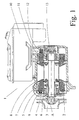
- FIG. 1 shows a centrifugal pump 1 with a pump housing 8, to which a pump controller 10 is attached.
- the pump impeller 3 is by means of the electric drive 2 via a Drive shaft 13 driven.
- the electric drive 2 is separated from the medium 14 by means of a partition 4.
- a Speed sensor 9 attached in the form of a coil, which the Rotation of the pump impeller 3 using an induction plate 6, which rotates with the pump impeller 3, is detected.
- the Speed sensor 9 is by means of a line 7, in particular a ribbon cable via an electrical connector with the pump control 10 in electrical connection.
- FIG. 2 shows an enlarged detail of the detail A of Figure 1.
- the speed sensor 9 consists of a Coil former 9a, which has a centered bore 9c.
- the Coil body 9a carries the coil windings 9b and is on the Ribbon line 7 attached in area 7a.
- the connection of the Cores or lines of the ribbon cable 7 with the Coil winding 9b is not shown.
- the coil 9 can by means of an adhesive connection with the Ribbon line 7 or its area 7h to be connected.
- the Bobbin 9a is on a projection or mandrel Winding cap 5 detachably attached.
- the ribbon cable 7 its area 7a lies between the coil former 9a and the end cap 5 firmly.
- the partition 4 prevents together with other sealing parts, not shown, that the medium 14 in the area 16 between the partition 4 and Winding cap 5 can penetrate.
- Figures 3a and 3b show a side plan view of the End cap 5.
- the leading to the pump control 10 Ribbon line 7 is only in the area of Winding cap 5 shown and is at the bottom of the figure cut off.
- the temperature sensor 15 is on the Ribbon cable 7b, 7c, which as in Figures 4, 4a and 4b can be an extension of the ribbon cable 7, attached.
- the line 7b, 7c is bent into a loop S.
- the loop diameter is dimensioned so that it in unmounted condition greater than the distance between the Partition 4, 4a and the end cap 5, 5b is so that it is pressed together during assembly. This creates one Resetting force that the temperature sensor 15 against the partition 4, 4a pressurized. Due to the small thickness of the Ribbon cable, the temperature sensor 15 either on the Outside (Fig. 3a) or on the inside (Fig. 3b) Loop S can be arranged.
- 3c shows a further embodiment of the invention, the temperature sensor 15 at the end of a stub 7d, which also with the ribbon cable 7 in electrical Connection can be attached.
- the stub 7d is by means of a spring F which is connected to the end cap 5 molded projection or mandrel 5c is held in the direction the partition 4 is pressurized, causing the temperature sensor 15 abuts on the side 4a of the partition 4.
- the spring F can then be dispensed with (FIG. 3d) if the Stub 7d has a sufficiently high rigidity and can serve as a leaf spring.
- Temperature sensor 15 in the middle of a stub 7e, 7f attach, this stub 7e, 7f with his one End is connected to the ribbon cable 7 and with his other end 7g in an L-shaped projection 5d End cap 5 is locked.
- the stub 7e, 7f is doing so much longer than the distance between the Speed sensor and the L-shaped projection to choose that the Stub 7e, 7f is compressed and thereby bulges.
- the bulge must be in the unmounted state of the pump be so large that the temperature sensor 15 in the assembled state still with a sufficiently large force against the side 4a of the Partition 4 is pressurized.
- FIG. 4 shows a ribbon cable 7, which is L-shaped is formed, the area 7 the feed line of the connector 12 to the area 7a, d. H. the Represents connection point for the speed sensor 9.
- the Ribbon cable 7 has two window-like recesses or Holes 18, 19. These holes 18, 19 to cover brought, the line areas 7b, 7c form the loop S.
- the ribbon cable 7, 7a, 7b, 7c has conductor tracks or wires 17, on which the speed sensor 9 and the temperature sensor 15 can be connected in parallel.
- the speed sensor 9 is in FIG. 4 not shown.
- FIGs 4a and 4b show further embodiments of the Ribbon cable 7, 7b, 7c, with at the ribbon cable 4a the speed sensor on the conductor tracks 20 and Temperature sensor 15 on the conductor tracks 21 of the ribbon cable 7 can be connected.
- the temperature sensor 15 is in its Dimensions held so that its contacts 15a a distance from each other, which is approximately the distance between the conductor tracks 21 from each other. This makes it possible to Temperature sensor 15 without additional connecting lines the conductor tracks 21 by a simple solder connection connect.
- the ribbon cable shown in Figure 4a is the speed sensor in the area of the recess 18 on the Ribbon line 7 attached.
- the one shown in Figure 4b In contrast, the cable is fastened in the area of the recess 19.
- the different arrangement of the speed sensor on the The result of the ribbon cable 7 is that, as in FIG. 5 shown, either the line end 7g directly on the Page 5b of the end cap 5 or the area 7a, from which the ribbon cable 7 for pump control 10 leads.
Landscapes
- Engineering & Computer Science (AREA)
- Microelectronics & Electronic Packaging (AREA)
- Power Engineering (AREA)
- Mechanical Engineering (AREA)
- General Engineering & Computer Science (AREA)
- Physics & Mathematics (AREA)
- General Physics & Mathematics (AREA)
- Control Of Non-Positive-Displacement Pumps (AREA)
- Structures Of Non-Positive Displacement Pumps (AREA)
Description
- Fig. 1
- Eine Querschnittsdarstellung einer Kreiselpumpe mit einer Pumpensteuerung;
- Fig. 2
- eine Ausschnittsvergrößerung des Bereichs A der Fig. 1;
- Fig. 3 und Fig. 3b
- das Andrücken des Temperatursensors gegen die Trennwand mittels der zur Schlaufe bzw. Auge gebogenen Zuführungsleitung;
- Fig. 3c
- das Andrücken des Temperatursensors gegen die Trennwand mittels einer Feder;
- Fig. 3d und Fig. 3e
- das Andrücken des Temperatursensors gegen die Trennwand mittels einer als Blattfeder ausgebildeten Zuführungsleitung;
- Fig. 4, Fig. 4a und Fig. 4b
- verschiedene Versionen der als Flachbandleitung ausgebildeten flexiblen Zuführungsleitung für den Drehzahlsensor und Temperatursensor;
- Fig. 5
- eine schematische Darstellung der Befestigung des Drehzahlsensors sowie der Schlaufe mit dem Temperatursensor an der Wickelkopfkappe.
- 1
- Pumpe
- 2
- Elektrische Antrieb; Ständerwicklung
- 3
- Pumpenlaufrad
- 4
- Trennwand
- 5
- Wickelkopfkappe
- 5a
- Vorsprung bzw. Dorn zur Halterung des Drehzahlsensors 9
- 5b
- Der Trennwand zugewandte Seite der Wickelkopfkappe
- 5c
- Federhalterung, insbesondere angeformter Vorsprung (Dorn)
- 5d
- L-förmiger Vorsprung zur Arretierung des Leitungsendes 7g
- 6
- Induktionsplatte
- 7
- Leitung; Flachbandleitung
- 7a
- Bereich der Leitung, der zwischen dem Drehzahlsensor und der Wickelkopfkappe einliegt
- 7b
- Leitungsbereich zwischen den Befestigungsstellen des Drehzahl- und Temperatursensors
- 7c
- Leitungsbereich zwischen der Befestigungsstelle des Temperatursensors und dem Kabelende 7g
- 7d
- Stichleitung
- 7e
- Leitungsbereich der Stichleitung zwischen den Befestigungsstellen des Drehzahl- und Temperatursensors
- 7f
- Leitungsbereich zwischen der Befestigungsstelle des Temperatursensors und dem Leitungsende 7g
- 7g
- Leitungsende
- 8
- Pumpengehäuse
- 9
- Drehzahlsensor
- 9a
- Spulenkörper
- 9b
- Windungen
- 9c
- Bohrung im Spulenkörper
- 10
- Pumpensteuerung
- 11
- Leitungsende mit Stecker
- 12
- Steckverbindung für Anschluß an die Pumpensteuerung 10
- 13
- Antriebswelle
- 14
- Fördermedium
- 15
- Temperatursensor
- 15a
- Anschlußstellen (Lötverbindungen) der Kontakte des Temperatursensors mit den Leiterbahnen 21
- 16
- Spalt zwischen Wickelkopfkappe und Trennwand
- 17
- Leiterbahnen der Flachbandleitung 7
- 18,19
- Fenster in Form von Bohrungen bzw. Materialaussparungen
- 20
- Leiterbahnen für Anschluß des Drehzahlsensors
- 21
- Leiterbahnen für Anschluß des Temperatursensors
- 22
- Auflagepunkt der Schlaufe S an der Wickelkopfkappe
- A
- Ausschnitt
- F
- Feder; Druckfeder
- S
- Schlaufe bzw. Auge
Claims (11)
- Pumpe (1) mit einem Pumpenlaufrad (3) und einem das Pumpenlaufrad (3) antreibenden Antrieb (2), wobei zwischen dem Pumpenlaufrad (3) und dem Antrieb (2) eine Trennwand (4) ist, und auf der dem Antrieb (2) zugewandten Seite der Trennwand (4) ein Drehzahlsensor (9) im Bereich des Pumpenlaufrades (3) angeordnet ist, und der Drehzahlsensor (9) mittels einer elektrischen Leitung (7) mit einer Steuerung (10) der Pumpe (1) in elektrischer Verbindung ist, dadurch gekennzeichnet, daß zusätzlich zum Drehzahlsensor (9) ein Temperatursensor (15) an der Leitung (7) angeschlossen ist, und der Temperatursensor (15) mittels einer Feder (F) gegen die Trennwand (4) oder einer mit dieser in thermisch leitender Verbindung befindlichen Wärmebrücke druckbeaufschlagbar ist.
- Pumpe (1) nach Anspruch 1, dadurch gekennzeichnet, daß der Temperatursensor (15) mittels eines zusätzlichen Leitungsstrangs (7b,7c,7d,7e,7f) mit der Leitung (7) in elektrischer Verbindung ist.
- Pumpe (1) nach Anspruch 2, dadurch gekennzeichnet, daß die Leitung (7) oder der zusätzliche Leitungsstrang (7b, 7c, 7d, 7e, 7f) die Feder (F) bildet, welche insbesondere als Blattfeder ausgebildet ist.
- Pumpe (1) nach Anspruch 3, dadurch gekennzeichnet, daß die Leitung (7) oder der zusätzliche Leitungsstrang (7b,7c,7d,7e,7f) gebogen ist und durch die Verbiegung eine Rückstellkraft erzeugbar ist, mittels der der Temperatursensor (15) gegen die Trennwand (4) oder einer mit dieser in thermisch leitender Verbindung befindlichen Wärmebrücke druckbeaufschlagbar ist.
- Pumpe (1) nach Anspruch 4, dadurch gekennzeichnet, daß die Leitung (7) oder der zusätzliche Leitungsstrang (7b,7c) zu einer Schlaufe oder einem Auge (S) gebogen ist.
- Pumpe (1) nach einem der vorherigen Ansprüche, dadurch gekennzeichnet, daß der Drehzahlsensor (9) eine Spule (9a,9b) ist, die an einer Wickelkopfkappe (5) des Antriebs (2) der Pumpe (1) insbesondere lösbar befestigt ist.
- Pumpe (1) nach einem der vorherigen Ansprüche, dadurch gekennzeichnet, daß die Schlaufe oder das Auge (S) von der Trennwand (4) und der Wickelkopfkappe (5) bei montierter Pumpe (1) zusammengedrückt ist und hierdurch die Andruckkraft für den Temperatursensor (15) an die Trennwand (4) oder Wärmebrücke erzeugbar ist.
- Pumpe (1) nach einem der vorherigen Ansprüche, dadurch gekennzeichnet, daß der Spulenkörper (9a) auf einem Vorsprung (5a) insbesondere Dorn der Wickelkopfkappe (5) aufsteckbar ist, wobei die Leitung (7,7a) zwischen dem Spulenkörper (9a) und der Wickelkopfkappe (5) einliegt.
- Pumpe (1) nach Anspruch 8, dadurch gekennzeichnet, daß die Leitung (7) und/oder der zusätzliche Leitungsstrang (7b,7c,7d,7e,7f) eine Flachbandleitung mit zwei in Längsrichtung des Kabels (7,7b,7c,7d,7e,7f) beabstandeten Fenstern oder Ausnehmungen (18,19) ist, wobei die Schlaufe oder das Auge (S) dadurch gebildet ist, daß beide Fenster oder Ausnehmungen (18,19) den Vorsprung (5a) umgreifen.
- Pumpe (1) nach einem der vorherigen Ansprüche, dadurch gekennzeichnet, daß der Temperatursensor (15) parallel zum Drehzahlsensor (9) geschaltet ist.
- Pumpe (1) nach einem der vorherigen Ansprüche, dadurch gekennzeichnet, daß der Temperatursensor (15) ein Thermoelement, temperaturabhängiger Widerstand, Photoleiter oder eine Photodiode ist.
Applications Claiming Priority (2)
| Application Number | Priority Date | Filing Date | Title |
|---|---|---|---|
| DE19706424 | 1997-02-19 | ||
| DE19706424A DE19706424A1 (de) | 1997-02-19 | 1997-02-19 | Pumpe mit Temperatur- und Drehzahlsensor |
Publications (2)
| Publication Number | Publication Date |
|---|---|
| EP0860611A1 EP0860611A1 (de) | 1998-08-26 |
| EP0860611B1 true EP0860611B1 (de) | 2002-08-14 |
Family
ID=7820748
Family Applications (1)
| Application Number | Title | Priority Date | Filing Date |
|---|---|---|---|
| EP97120701A Expired - Lifetime EP0860611B1 (de) | 1997-02-19 | 1997-11-26 | Pumpe mit Temperatur- und Drehzahlsensor |
Country Status (2)
| Country | Link |
|---|---|
| EP (1) | EP0860611B1 (de) |
| DE (2) | DE19706424A1 (de) |
Families Citing this family (7)
| Publication number | Priority date | Publication date | Assignee | Title |
|---|---|---|---|---|
| EP1085210A3 (de) | 1999-09-13 | 2004-03-31 | Siemens Aktiengesellschaft | Pumpe mit Temperatursensor im Gehäuse |
| DE10038550A1 (de) * | 1999-09-13 | 2001-05-03 | Mannesmann Vdo Ag | Pumpe |
| IT1318723B1 (it) * | 2000-08-03 | 2003-09-10 | Claber Spa | Pompa centrifuga raffreddata ad acqua. |
| DE10157194A1 (de) * | 2001-11-23 | 2003-06-05 | Wilo Gmbh | Spaltrohrpumpe mit Sensor |
| DE102006027002A1 (de) * | 2006-06-08 | 2007-12-13 | Oase Gmbh | Pumpemanordnung mit Drehzahlsteuerung |
| DE102010063581A1 (de) * | 2010-10-21 | 2012-04-26 | Robert Bosch Gmbh | Stator einer elektrischen Maschine |
| DE102016209457A1 (de) * | 2016-05-31 | 2017-11-30 | Zf Friedrichshafen Ag | Stator für eine elektrische Maschine |
Family Cites Families (5)
| Publication number | Priority date | Publication date | Assignee | Title |
|---|---|---|---|---|
| US4318073A (en) * | 1980-08-29 | 1982-03-02 | Amp Incorporated | Temperature sensor |
| DE3538225C2 (de) * | 1985-10-26 | 1997-08-14 | Wilo Gmbh | Kreiselpumpe oder Lüfter |
| DE3803597A1 (de) * | 1988-02-06 | 1989-08-31 | Bosch Gmbh Robert | Kombinierter drehzahl/temperatur-messwertaufnehmer |
| DE19505543C2 (de) * | 1995-02-18 | 2002-04-18 | Wilo Gmbh | Kreiselpumpe mit Drehzahlsensor |
| US5582508A (en) * | 1995-05-10 | 1996-12-10 | Chou; Fu-Hsiung | Auto-control device for lift pumps |
-
1997
- 1997-02-19 DE DE19706424A patent/DE19706424A1/de not_active Withdrawn
- 1997-11-26 EP EP97120701A patent/EP0860611B1/de not_active Expired - Lifetime
- 1997-11-26 DE DE59707964T patent/DE59707964D1/de not_active Expired - Lifetime
Also Published As
| Publication number | Publication date |
|---|---|
| DE59707964D1 (de) | 2002-09-19 |
| EP0860611A1 (de) | 1998-08-26 |
| DE19706424A1 (de) | 1998-08-20 |
Similar Documents
| Publication | Publication Date | Title |
|---|---|---|
| DE10308543B4 (de) | Drehmomentsensor | |
| DE112007003343B4 (de) | Aufbau eines Motoranschlusses | |
| DE102017215091A1 (de) | Anordnung und Verfahren zur Kontaktierung eines Temperatursensors an einem Wickelkopf einer Elektromaschine | |
| EP0860611A1 (de) | Pumpe mit Temperatur- und Drehzahlsensor | |
| DE3506763A1 (de) | Elektromotor in flachbauweise | |
| DE4014918A1 (de) | Elektromotor | |
| DE69304552T2 (de) | Verfahren zur Herstellung einer Leiterplatte für ein motorgetriebenes Betätigungselement und ein solches Betätigungselement | |
| EP1315272B1 (de) | Spaltrohrpumpe mit Temperatursensor | |
| EP4483083B1 (de) | Vorrichtung der fluidtechnik | |
| EP1661215A1 (de) | Feldgerät zur bestimmung und/oder berwachung einer prozessgrösse | |
| EP3970265B1 (de) | Temperaturmesseinrichtung für einen stator einer elektrischen maschine mit hairpin- oder stab-wellenwicklungen | |
| EP3669814A1 (de) | Medizinisches oder dentales instrument mit einem rfid-speicheretikett | |
| DE3501391A1 (de) | Gehaeuse fuer ein elektrisches bauteil | |
| DE202008008644U1 (de) | Raumsparender Servomotor | |
| WO2007128733A2 (de) | Kältegerät | |
| DE2607164B2 (de) | Elektrische Vielfachdurchführung, insbesondere für Gewinnungsmaschinen des Untertagebergbaues | |
| DE102020206149B4 (de) | Antriebsvorrichtung | |
| DE602004004785T2 (de) | Näherungssensorträger, kompressor, ventilplatte und kühler | |
| DE202012102722U1 (de) | Motor-Vorrichtung mit 2-seitig belastbarer Motorwelle | |
| EP1983539A2 (de) | Temperaturbegrenzer | |
| DE102018127022A1 (de) | Gehäuseelement und Sensorsystem zur Erfassung von Winkel- und Rotationsinformationen einer elektrischen Maschine | |
| EP1396909A1 (de) | Kabelzugentlastung | |
| EP1082785A1 (de) | Elektronisches steuergerät | |
| DE102018115905B4 (de) | Elektromaschinenkomponente, insbesondere für ein Elektrofahrzeug | |
| EP0563673A1 (de) | Federblech zum grossflächigen Kontaktieren zweier Gehäuseteile |
Legal Events
| Date | Code | Title | Description |
|---|---|---|---|
| PUAI | Public reference made under article 153(3) epc to a published international application that has entered the european phase |
Free format text: ORIGINAL CODE: 0009012 |
|
| 17P | Request for examination filed |
Effective date: 19980625 |
|
| AK | Designated contracting states |
Kind code of ref document: A1 Designated state(s): DE FR GB IT |
|
| AX | Request for extension of the european patent |
Free format text: AL;LT;LV;MK;RO;SI |
|
| AKX | Designation fees paid |
Free format text: DE FR GB IT |
|
| RBV | Designated contracting states (corrected) |
Designated state(s): DE FR GB IT |
|
| GRAG | Despatch of communication of intention to grant |
Free format text: ORIGINAL CODE: EPIDOS AGRA |
|
| GRAG | Despatch of communication of intention to grant |
Free format text: ORIGINAL CODE: EPIDOS AGRA |
|
| GRAH | Despatch of communication of intention to grant a patent |
Free format text: ORIGINAL CODE: EPIDOS IGRA |
|
| 17Q | First examination report despatched |
Effective date: 20020214 |
|
| GRAH | Despatch of communication of intention to grant a patent |
Free format text: ORIGINAL CODE: EPIDOS IGRA |
|
| GRAA | (expected) grant |
Free format text: ORIGINAL CODE: 0009210 |
|
| AK | Designated contracting states |
Kind code of ref document: B1 Designated state(s): DE FR GB IT |
|
| REG | Reference to a national code |
Ref country code: GB Ref legal event code: FG4D Free format text: NOT ENGLISH |
|
| REF | Corresponds to: |
Ref document number: 59707964 Country of ref document: DE Date of ref document: 20020919 |
|
| GBT | Gb: translation of ep patent filed (gb section 77(6)(a)/1977) |
Effective date: 20020916 |
|
| ET | Fr: translation filed | ||
| PLBE | No opposition filed within time limit |
Free format text: ORIGINAL CODE: 0009261 |
|
| STAA | Information on the status of an ep patent application or granted ep patent |
Free format text: STATUS: NO OPPOSITION FILED WITHIN TIME LIMIT |
|
| 26N | No opposition filed |
Effective date: 20030515 |
|
| PGFP | Annual fee paid to national office [announced via postgrant information from national office to epo] |
Ref country code: GB Payment date: 20131120 Year of fee payment: 17 |
|
| PGFP | Annual fee paid to national office [announced via postgrant information from national office to epo] |
Ref country code: IT Payment date: 20131118 Year of fee payment: 17 |
|
| PGFP | Annual fee paid to national office [announced via postgrant information from national office to epo] |
Ref country code: DE Payment date: 20141202 Year of fee payment: 18 |
|
| PGFP | Annual fee paid to national office [announced via postgrant information from national office to epo] |
Ref country code: FR Payment date: 20141128 Year of fee payment: 18 |
|
| GBPC | Gb: european patent ceased through non-payment of renewal fee |
Effective date: 20141126 |
|
| PG25 | Lapsed in a contracting state [announced via postgrant information from national office to epo] |
Ref country code: GB Free format text: LAPSE BECAUSE OF NON-PAYMENT OF DUE FEES Effective date: 20141126 |
|
| PG25 | Lapsed in a contracting state [announced via postgrant information from national office to epo] |
Ref country code: IT Free format text: LAPSE BECAUSE OF NON-PAYMENT OF DUE FEES Effective date: 20141126 |
|
| REG | Reference to a national code |
Ref country code: DE Ref legal event code: R119 Ref document number: 59707964 Country of ref document: DE |
|
| REG | Reference to a national code |
Ref country code: FR Ref legal event code: ST Effective date: 20160729 |
|
| PG25 | Lapsed in a contracting state [announced via postgrant information from national office to epo] |
Ref country code: DE Free format text: LAPSE BECAUSE OF NON-PAYMENT OF DUE FEES Effective date: 20160601 |
|
| PG25 | Lapsed in a contracting state [announced via postgrant information from national office to epo] |
Ref country code: FR Free format text: LAPSE BECAUSE OF NON-PAYMENT OF DUE FEES Effective date: 20151130 |