EP0859922B1 - Dispositif de securite pour boite de vitesses mecanique - Google Patents
Dispositif de securite pour boite de vitesses mecanique Download PDFInfo
- Publication number
- EP0859922B1 EP0859922B1 EP97929346A EP97929346A EP0859922B1 EP 0859922 B1 EP0859922 B1 EP 0859922B1 EP 97929346 A EP97929346 A EP 97929346A EP 97929346 A EP97929346 A EP 97929346A EP 0859922 B1 EP0859922 B1 EP 0859922B1
- Authority
- EP
- European Patent Office
- Prior art keywords
- gear
- safety device
- line
- hollow piston
- finger
- Prior art date
- Legal status (The legal status is an assumption and is not a legal conclusion. Google has not performed a legal analysis and makes no representation as to the accuracy of the status listed.)
- Expired - Lifetime
Links
- 230000007935 neutral effect Effects 0.000 claims description 6
- 238000006073 displacement reaction Methods 0.000 claims description 4
- 238000007373 indentation Methods 0.000 claims 1
- 241000282472 Canis lupus familiaris Species 0.000 description 15
- 230000006978 adaptation Effects 0.000 description 3
- 230000006835 compression Effects 0.000 description 3
- 238000007906 compression Methods 0.000 description 3
- 238000009434 installation Methods 0.000 description 1
- 230000007704 transition Effects 0.000 description 1
Images




Classifications
-
- F—MECHANICAL ENGINEERING; LIGHTING; HEATING; WEAPONS; BLASTING
- F16—ENGINEERING ELEMENTS AND UNITS; GENERAL MEASURES FOR PRODUCING AND MAINTAINING EFFECTIVE FUNCTIONING OF MACHINES OR INSTALLATIONS; THERMAL INSULATION IN GENERAL
- F16H—GEARING
- F16H61/00—Control functions within control units of change-speed- or reversing-gearings for conveying rotary motion ; Control of exclusively fluid gearing, friction gearing, gearings with endless flexible members or other particular types of gearing
- F16H61/18—Preventing unintentional or unsafe shift, e.g. preventing manual shift from highest gear to reverse gear
-
- F—MECHANICAL ENGINEERING; LIGHTING; HEATING; WEAPONS; BLASTING
- F16—ENGINEERING ELEMENTS AND UNITS; GENERAL MEASURES FOR PRODUCING AND MAINTAINING EFFECTIVE FUNCTIONING OF MACHINES OR INSTALLATIONS; THERMAL INSULATION IN GENERAL
- F16H—GEARING
- F16H61/00—Control functions within control units of change-speed- or reversing-gearings for conveying rotary motion ; Control of exclusively fluid gearing, friction gearing, gearings with endless flexible members or other particular types of gearing
- F16H61/18—Preventing unintentional or unsafe shift, e.g. preventing manual shift from highest gear to reverse gear
- F16H2061/185—Means, e.g. catches or interlocks, for preventing unintended shift into reverse gear
-
- F—MECHANICAL ENGINEERING; LIGHTING; HEATING; WEAPONS; BLASTING
- F16—ENGINEERING ELEMENTS AND UNITS; GENERAL MEASURES FOR PRODUCING AND MAINTAINING EFFECTIVE FUNCTIONING OF MACHINES OR INSTALLATIONS; THERMAL INSULATION IN GENERAL
- F16H—GEARING
- F16H61/00—Control functions within control units of change-speed- or reversing-gearings for conveying rotary motion ; Control of exclusively fluid gearing, friction gearing, gearings with endless flexible members or other particular types of gearing
- F16H61/24—Providing feel, e.g. to enable selection
- F16H2061/245—Ramp contours for generating force threshold, e.g. cams or pushers for generating additional resistance for a reverse path
-
- F—MECHANICAL ENGINEERING; LIGHTING; HEATING; WEAPONS; BLASTING
- F16—ENGINEERING ELEMENTS AND UNITS; GENERAL MEASURES FOR PRODUCING AND MAINTAINING EFFECTIVE FUNCTIONING OF MACHINES OR INSTALLATIONS; THERMAL INSULATION IN GENERAL
- F16H—GEARING
- F16H61/00—Control functions within control units of change-speed- or reversing-gearings for conveying rotary motion ; Control of exclusively fluid gearing, friction gearing, gearings with endless flexible members or other particular types of gearing
- F16H61/24—Providing feel, e.g. to enable selection
Definitions
- the present invention relates to the control of gearboxes mechanical. More specifically, it relates to a device for safety for mechanical gearbox of the type comprising an axis internal control shifted from the shift lever translational speeds to select a passage line from speeds and in rotation to pass a speed on the line selected, a shifting finger secured to the axis of internal control, and a set of dogs including at least one particular forward clutch dog and a reverse clutch dog adjacent respectively moved on either side of said axis alignment in opposite directions to shift the higher forward and reverse gear.
- FIG. 1 of the present application shows a safety device of known type comprising a spring press also conforming to the preamble of claim 1.
- Publication GB-2402104 describes a locking mechanism on this subject. of the reverse gear associated with the connecting elements between the end bottom of the gear shift lever, and a control shaft internal of the box.
- the present invention aims to prevent any involuntary passage while walking rear in a mechanical gearbox of the type specified above.
- a safety device for a mechanical gearbox which comprises a hollow body immobilized with respect to the casing containing a piston hollow elastically pushed against the passing finger by a first spring, the hollow piston containing a movable rod pushed back towards the finger passing through a second spring, so as to penetrate a obviously matching finger, when shifting highest forward, shifting the device into a position arming by preventing the withdrawal of the hollow piston inside the body hollow so as to prevent the engagement of the passing finger in the dog reverse when returning the particular forward clutch dog in the alignment of the other forward clutch dogs.
- this unit is in the form of a screwed cartridge in the mass of the housing.
- the unit in question also ensures the introduction of sensitive guidance in the maneuver when selecting the gear change lever.
- Sensitive guidance is obtained thanks to the cooperation of a piston hollow successively pushed back against the passing finger by a first spring defining the level of force to be applied to the lever shifting to the highest gear shift line high forward and by a second spring defining with the first spring the resistant force of the lever beyond this line of passage.
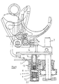
- Figure 1 shows in section a gearbox mechanism of known type, including in particular an internal control axis 2 moved from the shift lever in translation to select a shifting and rotating line for shift a speed on the selected line.
- an internal control axis 2 moved from the shift lever in translation to select a shifting and rotating line for shift a speed on the selected line.
- This figure also shows a pusher system from known type, containing a set of springs (not shown) which exert a force resistant to the operation of the change lever of speeds on the neutral line, by elastically pushing the passing finger 3 upwards.
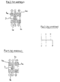
- FIGS. 2 and 4 illustrate a particular arrangement of the dogs 6a, to 6d, grouped together to be actuated by a single passing finger in forward and reverse.
- This arrangement includes two symmetrical dogs 6a, 6b, responsible for passing the first four gears front, and two adjacent dogs of particular shape overlapping mutually, so as to obtain a selection grid using the lever and passage of known type illustrated in FIG. 3, according to which, the reverse gear is slightly offset outward from the fifth line. Due to the proximity of these two lines of passage on the grid, the problem of the prohibition of passage in reverse when removing the fifth mentioned above, is therefore particularly critical as well with the arrangement of dogs of FIGS. 2 and 4 corresponding to a single passing finger, than with that of figure 1, actuated according to the same grid of selection and transition, illustrated in Figure 3.
- Figure 5 shows an internal box control system speeds of the type known from publication EP 139 261, compatible with the selection and passage grid in Figure 3, according to which the shifting finger 3a is integral with a cooperating arm 3b with a set of balls and springs in order to introduce a sensitive guidance in the speed control.
- this system does not provide any security measures to prohibit directly involuntary reverse gear.
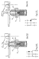
- the safety device 1 according to the invention which is the subject of the Figure 6, is mounted in the housing 7 of the gearbox, according to an arrangement similar to that of the pusher system of the Figure 1, but it is of course possible to provide other locations for this device, without departing from the scope of the invention.
- This device constitutes a compact unit attached to the casing 7, which is in the form of a cartridge 1, and can for example be screwed into the body of the housing 7 of a gearbox.
- it is designed for a maneuvered gearbox from a selection and passage grid corresponding to the figure 3. more precisely, it finds its application in a box of gears with an internal control axis 2 moved from the shift lever in translation to select a shifting line and rotating to shift a gear on the selected line, a shift finger 3 secured to the internal control shaft 2, a set of dog teeth 6a, 6b, 6c, 6d including at least one particular forward dog 6c and an adjacent 6d reverse dog moved respectively on either side of their dead center line in directions opposite to pass the fifth forward gear and the reverse.
- gearbox illustrated in Figure 6 has a double shift finger, but the device proposed also applies to an internal control mechanism single finger, such as that of FIGS. 2 and 4.
- This device illustrated by FIGS. 6, 8A, 9A, 10A, 11A and 12A, comprises a hollow body 8 immobilized with respect to the casing 7.
- the body 8 contains a hollow piston 9 pushed elastically against the finger passage before 3 by a first spring 11.
- the first spring 11 defines a first level of effort to apply to the gearshift lever up to the passage of fifth, while a third spring 12 defines with the first spring 11 the resistant force of the shift lever gears between the fifth line and the reverse line.
- this device performs a function of safety device to prevent involuntary shifting of reverse gear leaving the fifth.
- the hollow piston 9 contains a movable rod 14 pushed back towards the forward finger 3 by a second spring 13, so as to enter a recess corresponding 4 of the passing finger 3, during the passage into the fifth.
- the hollow body 9 contains movable lugs 16. These last cooperate with the rod 14 during the passage in fifth for move between a disarming position where they are pushed back to inside an annular groove 18 thereof, so as not to limit displacement of the hollow piston and the passage finger 3 in the direction fifth and reverse lines, and a position where they rest on the bottom of an inner groove 19 of the hollow piston 9 in order to prohibit the movement of the hollow piston 9 and forward finger 3 to the reverse line.
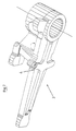
- Figure 7 relating to a compatible shifting finger 3 with the safety device 1 proposed by the invention, puts in evidence of the recess 4 on finger 3, receiving the end of the rod mobile 14, when arming the device 1.
- FIG. 8A shows the situation of the device 1, when the lever gear change is in neutral (see Figure 8B), i.e. on the passing line of the third and fourth reports of forward.
- the hollow piston 8 and the movable rod 14 are in abutment against finger 3, while the pins 16 are engaged in the annular groove 18 of the rod 14, and not in the groove inside 19 of the hollow body 8.
- the device is not armed.
- finger 3 simultaneously pushes the hollow piston 8 and the rod 14 inside the hollow body 8, against the first spring 11.
- finger 3 has pivoted with the control axis 2, so as to place its recess 4 opposite the rod 14. Since the rod 14 and the hollow piston 9 are not linked, the rod 14 can partially escape outside of the hollow piston 9. Simultaneously, the lugs 16 are pushed back by the rod 14 at the bottom of the internal grooves 19 of the hollow piston 9, in a position where they prohibit the displacement of the hollow piston 9 towards inside the hollow body 8. The safety device is then armed.
- the third spring 12 can be arranged at the inside of a bush 21 sliding axially in the hollow body 8 around a fixed axis 22, under the thrust of the hollow piston 9.
- the compression of the first spring indicates to the driver that it exceeds the pass line of third and fourth on the selection line, while the successive compression of the first and third spring, defining a higher level of effort, tells him that he is select reverse gear.
- the movable pins of the device have a length such that one of their ends reaches the bottom of the inner groove of the hollow body, when the other is in support on the cylindrical wall of the movable rod. In this situation, the safety device is stable and its mounting in the housing integrates easily into all assembly operations of the gearbox.
Landscapes
- Engineering & Computer Science (AREA)
- General Engineering & Computer Science (AREA)
- Mechanical Engineering (AREA)
- Gear-Shifting Mechanisms (AREA)
Description
- les figures 1, 2, 3, 4 et 5 se rapportent à l'art antérieur,
- la figure 6 représente le dispositif de commande de l'invention,
- la figure 7 met en évidence l'adaptation du doigt de commande de marche avant, rendue nécessaire par l'invention, et
- les figures 8A à 12C illustrent le fonctionnement de ce dispositif.
Claims (7)
- Dispositif de sécurité pour boíte de vitesses mécanique comportant un axe de commande interne (2) déplacé à partir du levier de changement de vitesses en translation pour sélectionner une ligne de passage de vitesses et en rotation pour passer une vitesse sur la ligne sélectionnée, un doigt de passage des vitesses (3) solidaire de l'axe de commande interne (2), un ensemble de crabots (6a, 6b, 6c, 6d) incluant au moins un crabot particulier de marche avant (6c) et un crabot de marche arrière (6d) adjacents déplacés respectivement de part et d'autre de leur ligne de point mort dans des directions opposées pour passer le rapport le plus élevé de marche avant et le rapport de marche arrière, le dispositif comportant un corps creux (8) immobilisé vis-à-vis du carter (7) et renfermant un piston creux (9) repoussé élastiquement contre le doigt de passage (3) par un premier ressort (11), caractérisé en ce que le piston creux renferme une tige mobile (14) repoussée en direction du doigt de passage (3) par un deuxième ressort (13), de façon à pénétrer dans un évidemment correspondant (4) du doigt de passage (3), lors du passage de rapport le plus élevé de marche avant, faisant passer le dispositif dans une position d'armement en empêchant le retrait du piston creux (9) à l'intérieur du corps creux (8) de façon à interdire l'engagement du doigt de passage (3) dans le crabot de marche arrière (6d) lors du retour du crabot particulier de marche avant (6c) dans l'alignement des autres crabots de marche avant (6a, 6b).
- Dispositif de sécurité selon la revendication 1, caractérisé en ce qu'il constitue une unité de commande compacte (1), rapportée à l'intérieur du carter (7) de la boíte.
- Dispositif de sécurité selon la revendication 1 ou 2, caractérisé en ce qu'il se présente sous la forme d'une cartouche (1) vissée dans la masse du carter (7).
- Dispositif de sécurité selon la revendication 1, 2 ou 3, caractérisé en ce que le corps creux (9) renferme des ergots mobiles (16) coopérant avec la tige (14) lors du passage sur le rapport le plus élevé de marche avant pour passer dans une position d'armement et que les ergots (16) sont repoussés par la tige (14) à l'intérieur d'une gorge intérieure (19) du corps creux en position d'armement.
- Dispositif de sécurité selon la revendication 4, caractérisé en ce que le retour du levier de changement de vitesses vers la ligne de point mort à partir du rapport le plus élevé de marche avant entraíne le retrait de la tige mobile (14) à l'intérieur du piston creux (9) en comprimant le deuxième ressort (13), tandis que les ergots (16) restent en position d'armement.
- Dispositif de sécurité selon l'une des revendications 4 ou 5, caractérisé en ce que le déplacement du levier de changement de vitesses sur la ligne de point mort en direction des rapports inférieurs de marche avant entraíne le retrait des ergots (16) en position de désarmement, sous la poussée transversale des rampes intérieures (17) du piston creux (9).
- Dispositif de sécurité selon l'une des revendications précédentes, caractérisé en ce qu'un troisième ressort (12) est disposé à l'intérieur d'une douille (21) coulissant axialement dans le corps creux (8) autour d'un axe (22) fixe sous la poussée du piston creux (9) entre la ligne de passage du rapport le plus élevé de marche avant, et la ligne de passage de la marche arrière.
Applications Claiming Priority (3)
| Application Number | Priority Date | Filing Date | Title |
|---|---|---|---|
| FR9607408A FR2749909B1 (fr) | 1996-06-14 | 1996-06-14 | Dispositif de securite pour boite de vitesses mecanique |
| FR9607408 | 1996-06-14 | ||
| PCT/FR1997/001068 WO1997047903A1 (fr) | 1996-06-14 | 1997-06-13 | Dispositif de securite pour boite de vitesses mecanique |
Publications (2)
| Publication Number | Publication Date |
|---|---|
| EP0859922A1 EP0859922A1 (fr) | 1998-08-26 |
| EP0859922B1 true EP0859922B1 (fr) | 2002-11-06 |
Family
ID=9493054
Family Applications (1)
| Application Number | Title | Priority Date | Filing Date |
|---|---|---|---|
| EP97929346A Expired - Lifetime EP0859922B1 (fr) | 1996-06-14 | 1997-06-13 | Dispositif de securite pour boite de vitesses mecanique |
Country Status (4)
| Country | Link |
|---|---|
| EP (1) | EP0859922B1 (fr) |
| DE (1) | DE69716869T2 (fr) |
| FR (1) | FR2749909B1 (fr) |
| WO (1) | WO1997047903A1 (fr) |
Cited By (1)
| Publication number | Priority date | Publication date | Assignee | Title |
|---|---|---|---|---|
| DE102006039954B4 (de) * | 2005-08-26 | 2012-03-29 | Gm Global Technology Operations Llc (N.D.Ges.D. Staates Delaware) | Rückstellfedervorrichtung und Schaltsteuermechanismus |
Families Citing this family (4)
| Publication number | Priority date | Publication date | Assignee | Title |
|---|---|---|---|---|
| DE10034736A1 (de) * | 1999-08-09 | 2001-04-26 | Luk Lamellen & Kupplungsbau | Getriebe |
| DE102014215914B4 (de) * | 2014-08-12 | 2017-03-02 | Schaeffler Technologies AG & Co. KG | Schaltdom und Schaltarretierung zur Erzeugung von variablen Schaltkräften |
| EP3212451B1 (fr) * | 2014-10-29 | 2020-12-23 | Eaton Corporation | Ensemble de changement de rapport comportant un encliquetage de position à deux étages à extrémité sphérique |
| FR3037116B1 (fr) * | 2015-06-05 | 2017-07-07 | Peugeot Citroen Automobiles Sa | Boite de vitesses manuelle d'un vehicule |
Family Cites Families (5)
| Publication number | Priority date | Publication date | Assignee | Title |
|---|---|---|---|---|
| US3866488A (en) * | 1972-01-24 | 1975-02-18 | Toyota Motor Co Ltd | Manually operated shift assembly with restraining action for shifting to reverse |
| US3937100A (en) * | 1974-08-15 | 1976-02-10 | Borg-Warner Corporation | Transmission shift control |
| JPS55102725A (en) * | 1979-01-30 | 1980-08-06 | Nissan Motor Co Ltd | Control mechanism of transmission |
| JPS6079419A (ja) * | 1983-10-07 | 1985-05-07 | Nissan Motor Co Ltd | 手動変速機の操作機構 |
| JPH0665909B2 (ja) * | 1984-07-09 | 1994-08-24 | 富士重工業株式会社 | 車両用変速歯車装置の変速操作機構 |
-
1996
- 1996-06-14 FR FR9607408A patent/FR2749909B1/fr not_active Expired - Fee Related
-
1997
- 1997-06-13 EP EP97929346A patent/EP0859922B1/fr not_active Expired - Lifetime
- 1997-06-13 DE DE69716869T patent/DE69716869T2/de not_active Expired - Lifetime
- 1997-06-13 WO PCT/FR1997/001068 patent/WO1997047903A1/fr not_active Ceased
Cited By (1)
| Publication number | Priority date | Publication date | Assignee | Title |
|---|---|---|---|---|
| DE102006039954B4 (de) * | 2005-08-26 | 2012-03-29 | Gm Global Technology Operations Llc (N.D.Ges.D. Staates Delaware) | Rückstellfedervorrichtung und Schaltsteuermechanismus |
Also Published As
| Publication number | Publication date |
|---|---|
| EP0859922A1 (fr) | 1998-08-26 |
| DE69716869D1 (de) | 2002-12-12 |
| DE69716869T2 (de) | 2003-09-11 |
| FR2749909A1 (fr) | 1997-12-19 |
| WO1997047903A1 (fr) | 1997-12-18 |
| FR2749909B1 (fr) | 1998-07-31 |
Similar Documents
| Publication | Publication Date | Title |
|---|---|---|
| FR2538777A1 (fr) | Atterrisseur pour aeronef | |
| FR3095483A1 (fr) | Boîtier de transmission et engin roulant équipé d'un tel boîtier de transmission | |
| EP2909066B1 (fr) | Ensemble de transmission pour engin automoteur, du type positionnable entre l'arbre primaire moteur et les roues dudit engin | |
| FR2772863A1 (fr) | Dispositif de commande pour boite de vitesses automatisee | |
| FR2774447A1 (fr) | Vehicule equipe d'un dispositif de manoeuvre automatisee d'une boite a vitesses | |
| FR2777963A1 (fr) | Dispositif de selection pour boite de vitesses automatique d'un vehicule automobile | |
| EP0501845B1 (fr) | Dispositif de commande d'une boîte de vitesses | |
| WO1997047903A1 (fr) | Dispositif de securite pour boite de vitesses mecanique | |
| EP0418107B1 (fr) | Dispositif de commande d'une boîte de vitesses de véhicule automobile | |
| WO1996023995A1 (fr) | Dispositif de commande d'une boite de vitesse | |
| FR2844570A1 (fr) | Dispositif de selection et de passage de vitesses pour une boite de vitesse pilotee de vehicule automobile | |
| WO1996023995A9 (fr) | Dispositif de commande d'une boite de vitesse | |
| FR2703422A1 (fr) | Dispositif de changement de vitesses pour une boîte de vitesses à engrenages d'un véhicule automobile. | |
| EP0685388B1 (fr) | Dispositif mécanique d'éjection comportant un piston mobile commandé en aller-retour | |
| EP1643168B1 (fr) | Dispositif de commande d'une boîte de vitesses pour véhicules automobiles | |
| EP0936130A1 (fr) | Arbre de direction télescopique notamment pour véhicule automobile | |
| EP2273158B1 (fr) | Système de commande pour une boîte de vitesses | |
| FR2515765A1 (fr) | Dispositif de commande du reducteur auxiliaire d'un vehicule automobile a quatre roues motrices | |
| EP0708277A1 (fr) | Dispositif et procédé de commande de boîte de vitesses | |
| EP0486349B1 (fr) | Dispositif de commande d'une boîte de vitesses de véhicule automobile | |
| EP1162380B1 (fr) | Ensemble synchroniseur pour une transmission de véhicule automobile | |
| FR2885981A1 (fr) | Dispositif de blocage provisoire d'un levier de selection et de passage de vitesses d'une boite de vitesse d'un vehicule automobile | |
| EP1036960B1 (fr) | Dispositif de montage et de démontage d'un câble de transmission reliant un levier de changement de vitesses à un verrou de sécurité pour boítes de vitesses de véhicules automobiles | |
| EP0716252B1 (fr) | Dispositif perfectionné de commande d'une boíte de vitesses | |
| EP1983231B1 (fr) | Dispositif de commande interne de boîtes de vitesses |
Legal Events
| Date | Code | Title | Description |
|---|---|---|---|
| PUAI | Public reference made under article 153(3) epc to a published international application that has entered the european phase |
Free format text: ORIGINAL CODE: 0009012 |
|
| 17P | Request for examination filed |
Effective date: 19980504 |
|
| AK | Designated contracting states |
Kind code of ref document: A1 Designated state(s): DE ES GB IT |
|
| 17Q | First examination report despatched |
Effective date: 20000508 |
|
| GRAG | Despatch of communication of intention to grant |
Free format text: ORIGINAL CODE: EPIDOS AGRA |
|
| GRAG | Despatch of communication of intention to grant |
Free format text: ORIGINAL CODE: EPIDOS AGRA |
|
| GRAH | Despatch of communication of intention to grant a patent |
Free format text: ORIGINAL CODE: EPIDOS IGRA |
|
| GRAH | Despatch of communication of intention to grant a patent |
Free format text: ORIGINAL CODE: EPIDOS IGRA |
|
| RAP1 | Party data changed (applicant data changed or rights of an application transferred) |
Owner name: RENAULT S.A.S. |
|
| GRAA | (expected) grant |
Free format text: ORIGINAL CODE: 0009210 |
|
| AK | Designated contracting states |
Kind code of ref document: B1 Designated state(s): DE ES GB IT |
|
| PG25 | Lapsed in a contracting state [announced via postgrant information from national office to epo] |
Ref country code: IT Free format text: LAPSE BECAUSE OF FAILURE TO SUBMIT A TRANSLATION OF THE DESCRIPTION OR TO PAY THE FEE WITHIN THE PRE;WARNING: LAPSES OF ITALIAN PATENTS WITH EFFECTIVE DATE BEFORE 2007 MAY HAVE OCCURRED AT ANY TIME BEFORE 2007. THE CORRECT EFFECTIVE DATE MAY BE DIFFERENT FROM THE ONE RECORDED.SCRIBED TIME-LIMIT Effective date: 20021106 Ref country code: GB Free format text: LAPSE BECAUSE OF FAILURE TO SUBMIT A TRANSLATION OF THE DESCRIPTION OR TO PAY THE FEE WITHIN THE PRESCRIBED TIME-LIMIT Effective date: 20021106 |
|
| REG | Reference to a national code |
Ref country code: GB Ref legal event code: FG4D Free format text: NOT ENGLISH |
|
| REF | Corresponds to: |
Ref document number: 69716869 Country of ref document: DE Date of ref document: 20021212 |
|
| GBV | Gb: ep patent (uk) treated as always having been void in accordance with gb section 77(7)/1977 [no translation filed] |
Effective date: 20021106 |
|
| PG25 | Lapsed in a contracting state [announced via postgrant information from national office to epo] |
Ref country code: ES Free format text: LAPSE BECAUSE OF FAILURE TO SUBMIT A TRANSLATION OF THE DESCRIPTION OR TO PAY THE FEE WITHIN THE PRESCRIBED TIME-LIMIT Effective date: 20030529 |
|
| PLBE | No opposition filed within time limit |
Free format text: ORIGINAL CODE: 0009261 |
|
| STAA | Information on the status of an ep patent application or granted ep patent |
Free format text: STATUS: NO OPPOSITION FILED WITHIN TIME LIMIT |
|
| 26N | No opposition filed |
Effective date: 20030807 |
|
| PGFP | Annual fee paid to national office [announced via postgrant information from national office to epo] |
Ref country code: DE Payment date: 20110622 Year of fee payment: 15 |
|
| REG | Reference to a national code |
Ref country code: DE Ref legal event code: R119 Ref document number: 69716869 Country of ref document: DE Effective date: 20130101 |
|
| PG25 | Lapsed in a contracting state [announced via postgrant information from national office to epo] |
Ref country code: DE Free format text: LAPSE BECAUSE OF NON-PAYMENT OF DUE FEES Effective date: 20130101 |