EP0859480A2 - Amplificateur optique à bande large à gain uniforme - Google Patents
Amplificateur optique à bande large à gain uniforme Download PDFInfo
- Publication number
- EP0859480A2 EP0859480A2 EP98300755A EP98300755A EP0859480A2 EP 0859480 A2 EP0859480 A2 EP 0859480A2 EP 98300755 A EP98300755 A EP 98300755A EP 98300755 A EP98300755 A EP 98300755A EP 0859480 A2 EP0859480 A2 EP 0859480A2
- Authority
- EP
- European Patent Office
- Prior art keywords
- signal
- optical
- input
- stage
- level
- Prior art date
- Legal status (The legal status is an assumption and is not a legal conclusion. Google has not performed a legal analysis and makes no representation as to the accuracy of the status listed.)
- Granted
Links
Images


Classifications
-
- H—ELECTRICITY
- H04—ELECTRIC COMMUNICATION TECHNIQUE
- H04B—TRANSMISSION
- H04B10/00—Transmission systems employing electromagnetic waves other than radio-waves, e.g. infrared, visible or ultraviolet light, or employing corpuscular radiation, e.g. quantum communication
- H04B10/29—Repeaters
- H04B10/291—Repeaters in which processing or amplification is carried out without conversion of the main signal from optical form
- H04B10/2912—Repeaters in which processing or amplification is carried out without conversion of the main signal from optical form characterised by the medium used for amplification or processing
-
- H—ELECTRICITY
- H04—ELECTRIC COMMUNICATION TECHNIQUE
- H04B—TRANSMISSION
- H04B10/00—Transmission systems employing electromagnetic waves other than radio-waves, e.g. infrared, visible or ultraviolet light, or employing corpuscular radiation, e.g. quantum communication
- H04B10/29—Repeaters
- H04B10/291—Repeaters in which processing or amplification is carried out without conversion of the main signal from optical form
- H04B10/293—Signal power control
- H04B10/294—Signal power control in a multiwavelength system, e.g. gain equalisation
- H04B10/2941—Signal power control in a multiwavelength system, e.g. gain equalisation using an equalising unit, e.g. a filter
-
- H—ELECTRICITY
- H01—ELECTRIC ELEMENTS
- H01S—DEVICES USING THE PROCESS OF LIGHT AMPLIFICATION BY STIMULATED EMISSION OF RADIATION [LASER] TO AMPLIFY OR GENERATE LIGHT; DEVICES USING STIMULATED EMISSION OF ELECTROMAGNETIC RADIATION IN WAVE RANGES OTHER THAN OPTICAL
- H01S3/00—Lasers, i.e. devices using stimulated emission of electromagnetic radiation in the infrared, visible or ultraviolet wave range
- H01S3/09—Processes or apparatus for excitation, e.g. pumping
- H01S3/091—Processes or apparatus for excitation, e.g. pumping using optical pumping
- H01S3/094—Processes or apparatus for excitation, e.g. pumping using optical pumping by coherent light
- H01S3/09408—Pump redundancy
-
- H—ELECTRICITY
- H04—ELECTRIC COMMUNICATION TECHNIQUE
- H04B—TRANSMISSION
- H04B2210/00—Indexing scheme relating to optical transmission systems
- H04B2210/003—Devices including multiple stages, e.g., multi-stage optical amplifiers or dispersion compensators
Definitions
- the present invention relates to optical communications systems and more particularly to optical systems employing optical amplifiers.
- a series of spaced-apart optical amplifiers are typically in the transmission path of optical communications system to amplify optical signals that are being transported over the path.
- a plurality of information bearing optical signals are typically transported over the optical path as multiplexed channels of different wavelengths. It has been noted that if the gain of an optical amplifier is different for the different channels being amplified, then the difference in gain accumulates as the signal channels pass through each of the series of amplifiers. Consequently, this results in the channels having different signal power levels and different signal to noise ratios, which undoubtedly impairs the performance of the optical communications system.
- the level of input power into an optical amplifier is affected by many factors, for example, the loss between the signal sources and the amplifier and/or the loss between amplifiers. As such, the level of input power to a series of optical amplifiers in a lightwave communication system may be substantially different.
- the input power may also vary over time as a result of changes in cable loss and aging of various devices in the optical system. It would be advantageous that the amplifiers maintain a flat gain spectrum for a large input dynamic range.
- a wavelength multiplexed optical signal composed of a number of individual optical component signals, e.g., N signals, having respective wavelengths of ⁇ 1 ⁇ 2 , ⁇ 3 .... ⁇ N , is transmitted from a source to a receiver via an optical transmission line, where N > 1 and may be, e.g., eight.
- the optical system includes a plurality of laser transmitters 110-1 through 110-N, multiplexer 120, a plurality of optical amplifiers disposed along optical transmission path 130, demultiplexer 140 and optical receivers 150-1 through 150- M.
- Each such transmitter outputs a respective information bearing optical signal having a unique wavelength, ⁇ i . It is assumed herein that such a signal is destined for one of the receivers 150-1 through 150-M.
- the transmission system has N optical channels respectively associated with transmitters 110-1 through 110-N.
- the N channels are identified by their respective wavelengths, ⁇ 1 , ⁇ 2 , ⁇ 3 and ⁇ N , which are sufficiently separated from one another to prevent signals in adjacent channels from interfering with one another. Such separation may be, for example, 200 GHz.
- the signals that are outputted by transmitters 110-1 through 110-N are combined (multiplexed) at MUX 120 and then outputted to optical transmission line 130.
- the outputted signal is then transported trough optical transmission system via amplifiers 100-1 through 100-K and optical cables 130 to DEMUX 140.
- DEMUX 140 separates the combined signals from one another and supplies the separated signals to respective ones of the receivers 150-1 through 150-M, where M may be, for example, equal to N.
- the input power into an optical amplifier depends either on the loss between the signal sources and the amplifier or on the loss between two amplifiers. As such, the input power to each of the optical amplifiers disposed in a lightwave communication system may be different. The input power may also vary over time as a result of changes in cable loss and the aging of various devices used in the system. For these reasons an amplifier has to maintain a flat gain spectrum for a large dynamic range of input signals.
- the gain spectrum of an optical amplifier which, for Wavelength Division Multiplexed (WDM) systems and networks, typically operates in deep saturation, depends strongly on the input power to the optical amplifier. What this means is that the gain spectrum of the optical amplifier will vary as a function of the level of the input power.
- the gain spectrum of an optical amplifier may be optimized (e.g., to decrease the dependence on the wavelength) for one level of input signal. However, such optimization would not hold for differential levels of input signal, but will change accordingly.
- the span losses may vary over time and from span to span, which causes optical amplifiers on different spans to experience large differences in "input powers".
- input powers we have recognized that it is very difficult to adjust precisely in practical systems such input power levels. If this is not dealt with, then the aforementioned problems will affect the performance, e.g.., bit error rate, of the optical system.
- the gain spectrum of an optical amplifier may be adjusted for different levels of input signal power, and thus for different span losses.
- FIG. 2 A detailed block diagram of an optical amplifier 100-i is shown in FIG. 2.
- Amplifier 100-i more particularly, receives a signal via optical input path 130 and conventional optical isolator device 5.
- Isolator device 5 allows the received optical signal to propagate toward rare-earth doped fiber 10 and prevents any spontaneous noise that is generated along the doped fiber 10 from flowing back into input fiber 130.
- WDM Wavelength Division Multiplexer
- Isolator 20 prevents noise and/or reflected signals traveling toward WDM 15 from interfering with the amplifier function occurring at the input stage comprising isolator 5, doped fiber 10 and WDM 15.
- coupler 55 combines the output from laser pumps 60 and 65 and then supplies a first portion of the combined output, i.e., pump power, to WDM 15 and supplies the remaining portion to WDM 40, in which such portions may or may not be equal.
- a first portion of the combined output i.e., pump power
- WDM 15 supplies the remaining portion to WDM 40, in which such portions may or may not be equal.
- two laser pumps are used in an illustrative embodiment of the invention to provide redundancy so that amplifier 100-i may continue to function properly when one of the laser pumps is not functioning properly.
- optical filter 25 which may be designed in a conventional way to filter out so-called Amplified Spontaneous Emission (ASE) noise outside of the signal band of the amplified signal, and thus prevent such noise from competing with the amplified signal for the available power (gain) provided at the second stage of amplifier 100.
- optical filter 25 may be further designed in a conventional way to operate at a wavelength band lower than the lower cutoff wavelength for the signal band, in which the latter wavelength may be, e.g., 1530 nanometers.
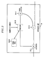
- variable attenuator unit Au 30 A broad block diagram of an illustrative embodiment of attenuator unit 30 is shown in FIG. 3 and includes a conventional electrically controlled variable signal attenuator (hereinafter “variable attenuator”) 30-5, conventional fiber coupler (splitter) 30-10, photo detector 30-15, optical fiber 1300-15 and processor 30-25 with power table 30-20 stored in the internal memory of processor 30-25.
- variable attenuator conventional electrically controlled variable signal attenuator
- splitter splitter
- photo detector 30-15 photo detector 30-15
- optical fiber 1300-15 optical fiber 1300-15
- processor 30-25 with power table 30-20 stored in the internal memory of processor 30-25.
- coupler 30-10 supplies a predetermined portion of the amplified signal supplied by filter 25 via variable attenuator 30-5 to photo detector 30-15 which outputs to processor 30-25 an electrical signal having a level proportional to the level of the optical signal supplied to detector 30-15.
- Processor 30-25 using the number of active channels contained in the signal received at the input of amplifier 100 as an index, accesses a power table 30-20 location containing a value representing the power level for the number of detected channels. Processor 30-25 then converts the level of the signal that it receives from photo diode 30-15 . « and compares that value with the value unloaded from the accessed power table 30-20 location. If the values compare with one another, then processor 30-25 does nothing. Otherwise, processor 30-25 sends signals to attenuator 30-25 to adjust (increase or decrease) the level of attenuation thereat until the aforementioned values compare with one another.
- the number of active channels may be detected by, for example, detecting and counting so-called pilot tones respectively identifying the active channels in the signal received via input fiber 130.
- pilot tones are disclosed in U. S. Patent No. 5,463,487 issued on October 31, 1995 to R. E. Epworth.
- the adjusted signal outputted by AU 30 is then supplied to "gain flattening" filter 35.
- Filter 35 more particularly, has a response that is the inverse of the gain spectrum of the input and output stages of amplifier 100 to a signal level corresponding to the level of the aforementioned adjusted signal, in which the output stage comprises WDM 40, doped fiber 45 and isolator 50.
- the filtered signal is then supplied to WDM 40 which combines the filtered signal and the pump power received via doped fiber 55-2 and supplies the combined signal to doped fiber 45, whereat optical amplification of the signal occurs in the manner discussed above.
- the amplified signal is then supplied to output optical fiber 130 via isolator 50.
- FIGs. 4A, 4B, 4D and 4E illustrate exemplary spectra of the signals that respectively appear at the input of isolator 5, input of filter 35, output of filter 35 and output of isolator 35 of amplifier 100-i. (Note that the spectra do not include ASE noise and are not to scale.) It is seen from those FIGs. that the spectrum is initially flat (FIG. 4A), then shaped by the input stage of amplifier 100 (FIG. 4B), then filtered (FIG. 4D) in accordance with the loss spectrum of filter 35 illustrated in FIG. 4C, and then amplified (FIG. 4E) by the output stage of amplifier 100-i.
- filters 25 and 35 could be implemented by a single filter.
- the amplifier could include more or less than two laser pumps.
- a single laser pump could replace the two laser pumps shown in FIG. 2.
- laser pumps 60 and 65 had the same wavelengths, in alternative arrangements such wavelengths may be different and the coupled arrangement may be different.
- one laser pump could be associated solely with the first amplifier stage and another laser pump could be associated solely with the second amplifier stage.
- Attenuator unit 30 may be implemented in a number of different ways.
- coupler 30-10 could be placed at the input to unit 30.
- the overall operation of attenuator unit 30 would change to accommodate that placement.
Applications Claiming Priority (2)
| Application Number | Priority Date | Filing Date | Title |
|---|---|---|---|
| US800870 | 1997-02-14 | ||
| US08/800,870 US5900969A (en) | 1997-02-14 | 1997-02-14 | Broadband flat gain optical amplifier |
Publications (3)
| Publication Number | Publication Date |
|---|---|
| EP0859480A2 true EP0859480A2 (fr) | 1998-08-19 |
| EP0859480A3 EP0859480A3 (fr) | 2002-01-16 |
| EP0859480B1 EP0859480B1 (fr) | 2005-01-19 |
Family
ID=25179598
Family Applications (1)
| Application Number | Title | Priority Date | Filing Date |
|---|---|---|---|
| EP98300755A Expired - Lifetime EP0859480B1 (fr) | 1997-02-14 | 1998-02-03 | Amplificateur optique à bande large à gain uniforme |
Country Status (5)
| Country | Link |
|---|---|
| US (1) | US5900969A (fr) |
| EP (1) | EP0859480B1 (fr) |
| JP (1) | JPH10242917A (fr) |
| CA (1) | CA2227247C (fr) |
| DE (1) | DE69828658T2 (fr) |
Cited By (5)
| Publication number | Priority date | Publication date | Assignee | Title |
|---|---|---|---|---|
| WO1999043117A2 (fr) * | 1998-02-20 | 1999-08-26 | Sdl, Inc. | Amplificateurs a fibre a gain egalise, evolutifs, pour applications de multiplexage par repartition en longueur d'onde (wdm) |
| WO1999066610A1 (fr) * | 1998-06-19 | 1999-12-23 | Lucent Technologies Inc. | Commande d'inclinaison de gain comprenant des attenuateurs a niveau intermediaire dans des amplificateurs a fibre dopee a l'erbium |
| EP1035670A2 (fr) * | 1999-03-08 | 2000-09-13 | Lucent Technologies Inc. | Amplificateur optique disposé pour décaler le gain Raman |
| EP1788732A2 (fr) | 2005-11-16 | 2007-05-23 | Fujitsu Limited | Amplificateur optique |
| US7856182B2 (en) | 2001-04-23 | 2010-12-21 | Transmode Systems Ab | Optical CWDM-system |
Families Citing this family (48)
| Publication number | Priority date | Publication date | Assignee | Title |
|---|---|---|---|---|
| US6025947A (en) | 1996-05-02 | 2000-02-15 | Fujitsu Limited | Controller which controls a variable optical attenuator to control the power level of a wavelength-multiplexed optical signal when the number of channels are varied |
| GB2314714B (en) * | 1996-06-26 | 2000-04-05 | Northern Telecom Ltd | Optical amplifier modules |
| SE509968C2 (sv) * | 1997-02-14 | 1999-03-29 | Ericsson Telefon Ab L M | Optisk förstärkare med variabel förstärkning |
| WO1998036479A1 (fr) * | 1997-02-18 | 1998-08-20 | Nippon Telegraph And Telephone Corporation | Amplificateur optique et systeme de transmission l'utilisant |
| JPH11127135A (ja) * | 1997-10-20 | 1999-05-11 | Fujitsu Ltd | 波長多重光伝送装置 |
| EP0914015B1 (fr) * | 1997-10-28 | 2006-12-20 | Nec Corporation | Multiplexeur optique a insertion-extraction |
| US6603596B2 (en) * | 1998-03-19 | 2003-08-05 | Fujitsu Limited | Gain and signal level adjustments of cascaded optical amplifiers |
| US6236487B1 (en) * | 1998-07-21 | 2001-05-22 | Corvis Corporation | Optical communication control system |
| US6839522B2 (en) | 1998-07-21 | 2005-01-04 | Corvis Corporation | Optical signal varying devices, systems and methods |
| US6344922B1 (en) * | 1998-07-21 | 2002-02-05 | Corvis Corporation | Optical signal varying devices |
| JP3134854B2 (ja) * | 1998-09-07 | 2001-02-13 | 日本電気株式会社 | 光増幅器 |
| US6356383B1 (en) | 1999-04-02 | 2002-03-12 | Corvis Corporation | Optical transmission systems including optical amplifiers apparatuses and methods |
| US6563614B1 (en) * | 1999-05-21 | 2003-05-13 | Corvis Corporation | Optical transmission system and amplifier control apparatuses and methods |
| US6587261B1 (en) * | 1999-05-24 | 2003-07-01 | Corvis Corporation | Optical transmission systems including optical amplifiers and methods of use therein |
| JP4340355B2 (ja) * | 1999-07-06 | 2009-10-07 | 株式会社日立コミュニケーションテクノロジー | 波長利得特性シフトフィルタ、光伝送装置および光伝送方法 |
| FR2800219B1 (fr) * | 1999-10-22 | 2006-06-30 | Algety Telecom | Procede d'ajustement de puissance pour un systeme de transmission optique a multiplexage en longueur d'onde |
| FR2800218B1 (fr) * | 1999-10-22 | 2002-01-11 | Algety Telecom | Systeme de transmission par fibre optique utilisant des impulsions rz |
| JP2001196671A (ja) * | 2000-01-06 | 2001-07-19 | Nec Corp | 波長多重伝送用光ファイバ増幅器 |
| US6344925B1 (en) | 2000-03-03 | 2002-02-05 | Corvis Corporation | Optical systems and methods and optical amplifiers for use therein |
| US6353497B1 (en) | 2000-03-03 | 2002-03-05 | Optical Coating Laboratory, Inc. | Integrated modular optical amplifier |
| US6466362B1 (en) * | 2000-08-31 | 2002-10-15 | Ciena Corporation | Hybrid amplifier and control method herefor that minimizes a noise figure for particular span loss |
| US6377396B1 (en) | 2000-09-26 | 2002-04-23 | Onetta, Inc. | Optical amplifiers with variable optical attenuation for use in fiber-optic communications systems |
| US6782199B1 (en) | 2000-09-29 | 2004-08-24 | Onetta, Inc. | Optical communications systems with optical subsystem communications links |
| US6414788B1 (en) | 2000-10-02 | 2002-07-02 | Onetta, Inc. | Optical amplifier system with transient control |
| US6424457B1 (en) | 2000-10-06 | 2002-07-23 | Onetta, Inc. | Optical amplifiers and methods for manufacturing optical amplifiers |
| US6417961B1 (en) | 2000-10-10 | 2002-07-09 | Onetta, Inc. | Optical amplifiers with dispersion compensation |
| US6341034B1 (en) | 2000-10-18 | 2002-01-22 | Onetta Inc. | Optical amplifier system with transient control using spectrally filtered input |
| US6498677B1 (en) | 2000-10-23 | 2002-12-24 | Onetta, Inc. | Optical amplifier systems with transient control |
| US6441950B1 (en) | 2000-11-03 | 2002-08-27 | Onetta, Inc. | Distributed raman amplifier systems with transient control |
| US6433924B1 (en) | 2000-11-14 | 2002-08-13 | Optical Coating Laboratory, Inc. | Wavelength-selective optical amplifier |
| US6542287B1 (en) | 2000-12-12 | 2003-04-01 | Onetta, Inc. | Optical amplifier systems with transient control |
| US6396623B1 (en) | 2000-12-19 | 2002-05-28 | Onetta, Inc. | Wide-band optical amplifiers with interleaved gain stages |
| US6633430B1 (en) * | 2001-02-15 | 2003-10-14 | Onetta, Inc. | Booster amplifier with spectral control for optical communications systems |
| US6417965B1 (en) | 2001-02-16 | 2002-07-09 | Onetta, Inc. | Optical amplifier control system |
| US6522459B1 (en) | 2001-02-22 | 2003-02-18 | Onetta, Inc. | Temperature control and monitoring of optical detector components in an optical communication system |
| US6476961B1 (en) | 2001-04-26 | 2002-11-05 | Onetta, Inc. | Optical amplifier systems with transient control |
| US6556345B1 (en) | 2001-06-21 | 2003-04-29 | Onetta, Inc. | Optical network equipment with control and data paths |
| US6687049B1 (en) | 2001-07-03 | 2004-02-03 | Onetta, Inc. | Optical amplifiers with stable output power under low input power conditions |
| US6944399B2 (en) * | 2001-08-28 | 2005-09-13 | Dorsal Networks, Inc. | Methods of signal substitution for maintenance of amplifier saturation |
| US6907195B2 (en) * | 2001-08-28 | 2005-06-14 | Dorsal Networks, Inc. | Terminals having sub-band substitute signal control in optical communication systems |
| US6577789B1 (en) | 2001-09-26 | 2003-06-10 | Onetta, Inc. | Double-pass optical amplifiers and optical network equipment |
| US6690505B1 (en) | 2001-09-28 | 2004-02-10 | Onetta, Inc. | Optical network equipment with gain transient control and automatic drift compensation |
| US6768833B2 (en) * | 2002-09-06 | 2004-07-27 | Corvis Corporation | Optical communications systems including a branching unit and associated devices and methods |
| KR100609698B1 (ko) * | 2004-06-09 | 2006-08-08 | 한국전자통신연구원 | 파장분할다중방식 수동형 광가입자망 시스템 및광원생성방법 |
| US8482850B2 (en) * | 2009-03-31 | 2013-07-09 | Ipg Photonics Corporation | Multi-stage erbium-doped fiber amplifier with a single programmable logic device control circuit and method of controlling thereof |
| JPWO2012053320A1 (ja) * | 2010-10-22 | 2014-02-24 | 日本電気株式会社 | 励起光分配装置、励起光分配方法、光増幅システム及びノード装置 |
| US9300396B2 (en) | 2012-11-13 | 2016-03-29 | At&T Intellectual Property I, L.P. | Fast optical link control adaptation using a channel monitor |
| CN114696188A (zh) * | 2020-12-30 | 2022-07-01 | 华为技术有限公司 | 光信号放大装置及相关光通信设备 |
Citations (4)
| Publication number | Priority date | Publication date | Assignee | Title |
|---|---|---|---|---|
| EP0695050A1 (fr) * | 1994-07-25 | 1996-01-31 | PIRELLI CAVI S.p.A. | Système de télécommunication amplifié pour transmission à multiplexage en longueurs d'ondes avec égalisation de puissance de sortie |
| EP0762691A2 (fr) * | 1995-09-08 | 1997-03-12 | Alcatel N.V. | Procédé et système d'égalisation des niveaux respectifs de puissance des canaux d'un signal optique spectralement multiplexé |
| GB2310094A (en) * | 1996-02-07 | 1997-08-13 | Fujitsu Ltd | Optical equalization and amplification of multi-wavelength light |
| WO1997050157A1 (fr) * | 1996-06-26 | 1997-12-31 | Northern Telecom Limited | Modules d'amplificateurs optiques |
Family Cites Families (6)
| Publication number | Priority date | Publication date | Assignee | Title |
|---|---|---|---|---|
| US5225922A (en) * | 1991-11-21 | 1993-07-06 | At&T Bell Laboratories | Optical transmission system equalizer |
| JPH08501158A (ja) * | 1992-06-01 | 1996-02-06 | ブリテイッシュ・テレコミュニケーションズ・パブリック・リミテッド・カンパニー | 予め選択された減衰対波長特性を有するフィルタ |
| US5572443A (en) * | 1993-05-11 | 1996-11-05 | Yamaha Corporation | Acoustic characteristic correction device |
| US5579143A (en) * | 1993-06-04 | 1996-11-26 | Ciena Corporation | Optical system with tunable in-fiber gratings |
| GB2280561B (en) * | 1993-07-31 | 1997-03-26 | Northern Telecom Ltd | Optical transmission system |
| JP2625386B2 (ja) * | 1994-07-28 | 1997-07-02 | 日本電気株式会社 | 光源装置 |
-
1997
- 1997-02-14 US US08/800,870 patent/US5900969A/en not_active Expired - Lifetime
-
1998
- 1998-01-19 CA CA002227247A patent/CA2227247C/fr not_active Expired - Lifetime
- 1998-02-03 DE DE69828658T patent/DE69828658T2/de not_active Expired - Lifetime
- 1998-02-03 EP EP98300755A patent/EP0859480B1/fr not_active Expired - Lifetime
- 1998-02-10 JP JP10028928A patent/JPH10242917A/ja active Pending
Patent Citations (4)
| Publication number | Priority date | Publication date | Assignee | Title |
|---|---|---|---|---|
| EP0695050A1 (fr) * | 1994-07-25 | 1996-01-31 | PIRELLI CAVI S.p.A. | Système de télécommunication amplifié pour transmission à multiplexage en longueurs d'ondes avec égalisation de puissance de sortie |
| EP0762691A2 (fr) * | 1995-09-08 | 1997-03-12 | Alcatel N.V. | Procédé et système d'égalisation des niveaux respectifs de puissance des canaux d'un signal optique spectralement multiplexé |
| GB2310094A (en) * | 1996-02-07 | 1997-08-13 | Fujitsu Ltd | Optical equalization and amplification of multi-wavelength light |
| WO1997050157A1 (fr) * | 1996-06-26 | 1997-12-31 | Northern Telecom Limited | Modules d'amplificateurs optiques |
Cited By (10)
| Publication number | Priority date | Publication date | Assignee | Title |
|---|---|---|---|---|
| WO1999043117A2 (fr) * | 1998-02-20 | 1999-08-26 | Sdl, Inc. | Amplificateurs a fibre a gain egalise, evolutifs, pour applications de multiplexage par repartition en longueur d'onde (wdm) |
| WO1999043117A3 (fr) * | 1998-02-20 | 1999-12-29 | Sdl Inc | Amplificateurs a fibre a gain egalise, evolutifs, pour applications de multiplexage par repartition en longueur d'onde (wdm) |
| US6236498B1 (en) | 1998-02-20 | 2001-05-22 | Sdl, Inc. | Upgradable, gain flattened fiber amplifiers for WDM applications |
| US6388806B1 (en) | 1998-02-20 | 2002-05-14 | Sdl, Inc. | Upgradable, gain flattened fiber amplifiers for WDM applications |
| WO1999066610A1 (fr) * | 1998-06-19 | 1999-12-23 | Lucent Technologies Inc. | Commande d'inclinaison de gain comprenant des attenuateurs a niveau intermediaire dans des amplificateurs a fibre dopee a l'erbium |
| EP1035670A2 (fr) * | 1999-03-08 | 2000-09-13 | Lucent Technologies Inc. | Amplificateur optique disposé pour décaler le gain Raman |
| EP1035670A3 (fr) * | 1999-03-08 | 2004-03-03 | Lucent Technologies Inc. | Amplificateur optique disposé pour décaler le gain Raman |
| US7856182B2 (en) | 2001-04-23 | 2010-12-21 | Transmode Systems Ab | Optical CWDM-system |
| EP1788732A2 (fr) | 2005-11-16 | 2007-05-23 | Fujitsu Limited | Amplificateur optique |
| EP1788732A3 (fr) * | 2005-11-16 | 2007-12-05 | Fujitsu Limited | Amplificateur optique |
Also Published As
| Publication number | Publication date |
|---|---|
| CA2227247C (fr) | 2002-05-28 |
| US5900969A (en) | 1999-05-04 |
| EP0859480B1 (fr) | 2005-01-19 |
| DE69828658T2 (de) | 2006-04-27 |
| JPH10242917A (ja) | 1998-09-11 |
| CA2227247A1 (fr) | 1998-08-14 |
| DE69828658D1 (de) | 2005-02-24 |
| EP0859480A3 (fr) | 2002-01-16 |
Similar Documents
| Publication | Publication Date | Title |
|---|---|---|
| US5900969A (en) | Broadband flat gain optical amplifier | |
| EP0944190B1 (fr) | Réglages des gains et des niveaux de signal d' amplificateurs optiques en cascade | |
| US6288836B1 (en) | Optical amplifier and optical communication system having the optical amplifier | |
| US6429966B1 (en) | Multistage optical amplifier with Raman and EDFA stages | |
| US6256141B1 (en) | Optical amplification apparatus | |
| EP0910139A2 (fr) | Amplificateur optique et système de transmission optique comprenant tel amplificateur | |
| EP1035670A2 (fr) | Amplificateur optique disposé pour décaler le gain Raman | |
| US7554718B2 (en) | Fast dynamic gain control in an optical fiber amplifier | |
| JP2734969B2 (ja) | 波長多重伝送用光ファイバ増幅器 | |
| US6501594B1 (en) | Long-band fiber amplifier using feedback loop | |
| JPH10257028A (ja) | 遠隔励起方式の波長多重光伝送システム | |
| US6373625B1 (en) | Method, apparatus, and system for optical amplification | |
| JPH07221712A (ja) | 調節された光増幅器 | |
| EP1073166A2 (fr) | Amplificateur à fibre optique en bande L avec boucle de contre-réaction | |
| JP3068500B2 (ja) | 光信号増幅伝送方式 | |
| US6483636B1 (en) | Optical amplifier | |
| US6823107B2 (en) | Method and device for optical amplification | |
| JP3217037B2 (ja) | 多段光ファイバ増幅器 | |
| US8351112B2 (en) | Optical amplifier | |
| US7672042B2 (en) | Fast dynamic gain control in an optical fiber amplifier | |
| US6456428B1 (en) | Optical amplifier | |
| US6441952B1 (en) | Apparatus and method for channel monitoring in a hybrid distributed Raman/EDFA optical amplifier | |
| EP1696524A1 (fr) | Contrôle rapide de gain dynamique dans un amplificateur à fibre optique | |
| US6646792B2 (en) | Light amplifier and light transmission system using the same | |
| US7042632B2 (en) | Raman amplifier |
Legal Events
| Date | Code | Title | Description |
|---|---|---|---|
| PUAI | Public reference made under article 153(3) epc to a published international application that has entered the european phase |
Free format text: ORIGINAL CODE: 0009012 |
|
| AK | Designated contracting states |
Kind code of ref document: A2 Designated state(s): AT BE CH DE DK ES FI FR GB GR IE IT LI LU MC NL PT SE Kind code of ref document: A2 Designated state(s): DE FR GB |
|
| AX | Request for extension of the european patent |
Free format text: AL;LT;LV;MK;RO;SI |
|
| PUAL | Search report despatched |
Free format text: ORIGINAL CODE: 0009013 |
|
| AK | Designated contracting states |
Kind code of ref document: A3 Designated state(s): AT BE CH DE DK ES FI FR GB GR IE IT LI LU MC NL PT SE |
|
| AX | Request for extension of the european patent |
Free format text: AL;LT;LV;MK;RO;SI |
|
| 17P | Request for examination filed |
Effective date: 20020708 |
|
| AKX | Designation fees paid |
Free format text: DE FR GB |
|
| 17Q | First examination report despatched |
Effective date: 20031006 |
|
| GRAP | Despatch of communication of intention to grant a patent |
Free format text: ORIGINAL CODE: EPIDOSNIGR1 |
|
| GRAS | Grant fee paid |
Free format text: ORIGINAL CODE: EPIDOSNIGR3 |
|
| GRAA | (expected) grant |
Free format text: ORIGINAL CODE: 0009210 |
|
| AK | Designated contracting states |
Kind code of ref document: B1 Designated state(s): DE FR GB |
|
| REG | Reference to a national code |
Ref country code: GB Ref legal event code: FG4D |
|
| REG | Reference to a national code |
Ref country code: IE Ref legal event code: FG4D |
|
| REF | Corresponds to: |
Ref document number: 69828658 Country of ref document: DE Date of ref document: 20050224 Kind code of ref document: P |
|
| PLBE | No opposition filed within time limit |
Free format text: ORIGINAL CODE: 0009261 |
|
| STAA | Information on the status of an ep patent application or granted ep patent |
Free format text: STATUS: NO OPPOSITION FILED WITHIN TIME LIMIT |
|
| ET | Fr: translation filed | ||
| 26N | No opposition filed |
Effective date: 20051020 |
|
| REG | Reference to a national code |
Ref country code: GB Ref legal event code: 732E Free format text: REGISTERED BETWEEN 20131031 AND 20131106 |
|
| REG | Reference to a national code |
Ref country code: FR Ref legal event code: CD Owner name: ALCATEL-LUCENT USA INC. Effective date: 20131122 |
|
| REG | Reference to a national code |
Ref country code: FR Ref legal event code: GC Effective date: 20140410 |
|
| REG | Reference to a national code |
Ref country code: FR Ref legal event code: RG Effective date: 20141015 |
|
| REG | Reference to a national code |
Ref country code: FR Ref legal event code: PLFP Year of fee payment: 18 |
|
| REG | Reference to a national code |
Ref country code: FR Ref legal event code: PLFP Year of fee payment: 19 |
|
| REG | Reference to a national code |
Ref country code: FR Ref legal event code: PLFP Year of fee payment: 20 |
|
| PGFP | Annual fee paid to national office [announced via postgrant information from national office to epo] |
Ref country code: FR Payment date: 20170217 Year of fee payment: 20 Ref country code: DE Payment date: 20170217 Year of fee payment: 20 |
|
| PGFP | Annual fee paid to national office [announced via postgrant information from national office to epo] |
Ref country code: GB Payment date: 20170216 Year of fee payment: 20 |
|
| REG | Reference to a national code |
Ref country code: DE Ref legal event code: R071 Ref document number: 69828658 Country of ref document: DE |
|
| REG | Reference to a national code |
Ref country code: GB Ref legal event code: PE20 Expiry date: 20180202 |
|
| PG25 | Lapsed in a contracting state [announced via postgrant information from national office to epo] |
Ref country code: GB Free format text: LAPSE BECAUSE OF EXPIRATION OF PROTECTION Effective date: 20180202 |