EP0859128A1 - Turbine disc with cooling channels - Google Patents
Turbine disc with cooling channels Download PDFInfo
- Publication number
- EP0859128A1 EP0859128A1 EP98101046A EP98101046A EP0859128A1 EP 0859128 A1 EP0859128 A1 EP 0859128A1 EP 98101046 A EP98101046 A EP 98101046A EP 98101046 A EP98101046 A EP 98101046A EP 0859128 A1 EP0859128 A1 EP 0859128A1
- Authority
- EP
- European Patent Office
- Prior art keywords
- cooling air
- disk
- disc
- groove
- turbine impeller
- Prior art date
- Legal status (The legal status is an assumption and is not a legal conclusion. Google has not performed a legal analysis and makes no representation as to the accuracy of the status listed.)
- Granted
Links
Images

Classifications
-
- F—MECHANICAL ENGINEERING; LIGHTING; HEATING; WEAPONS; BLASTING
- F01—MACHINES OR ENGINES IN GENERAL; ENGINE PLANTS IN GENERAL; STEAM ENGINES
- F01D—NON-POSITIVE DISPLACEMENT MACHINES OR ENGINES, e.g. STEAM TURBINES
- F01D5/00—Blades; Blade-carrying members; Heating, heat-insulating, cooling or antivibration means on the blades or the members
- F01D5/02—Blade-carrying members, e.g. rotors
- F01D5/08—Heating, heat-insulating or cooling means
- F01D5/081—Cooling fluid being directed on the side of the rotor disc or at the roots of the blades
-
- F—MECHANICAL ENGINEERING; LIGHTING; HEATING; WEAPONS; BLASTING
- F01—MACHINES OR ENGINES IN GENERAL; ENGINE PLANTS IN GENERAL; STEAM ENGINES
- F01D—NON-POSITIVE DISPLACEMENT MACHINES OR ENGINES, e.g. STEAM TURBINES
- F01D5/00—Blades; Blade-carrying members; Heating, heat-insulating, cooling or antivibration means on the blades or the members
- F01D5/02—Blade-carrying members, e.g. rotors
- F01D5/08—Heating, heat-insulating or cooling means
- F01D5/085—Heating, heat-insulating or cooling means cooling fluid circulating inside the rotor
- F01D5/087—Heating, heat-insulating or cooling means cooling fluid circulating inside the rotor in the radial passages of the rotor disc
-
- F—MECHANICAL ENGINEERING; LIGHTING; HEATING; WEAPONS; BLASTING
- F01—MACHINES OR ENGINES IN GENERAL; ENGINE PLANTS IN GENERAL; STEAM ENGINES
- F01D—NON-POSITIVE DISPLACEMENT MACHINES OR ENGINES, e.g. STEAM TURBINES
- F01D5/00—Blades; Blade-carrying members; Heating, heat-insulating, cooling or antivibration means on the blades or the members
- F01D5/30—Fixing blades to rotors; Blade roots ; Blade spacers
- F01D5/3007—Fixing blades to rotors; Blade roots ; Blade spacers of axial insertion type
- F01D5/3015—Fixing blades to rotors; Blade roots ; Blade spacers of axial insertion type with side plates
Landscapes
- Engineering & Computer Science (AREA)
- Mechanical Engineering (AREA)
- General Engineering & Computer Science (AREA)
- Turbine Rotor Nozzle Sealing (AREA)
Abstract
Description
Die Erfindung betrifft eine Turbinen-Laufradscheibe mit von der Scheibenstirnseite ausgehenden Kühlluftkanälen, die in den Scheibennuten, in welche luftgekühlte Turbinenschaufeln eingesetzt sind, münden. Zum technischen Umfeld wird beispielshalber auf die DE 29 47 521 A1 und die DE 34 44 586 A1 verwiesen.The invention relates to a turbine impeller disk from the disk end face outgoing cooling air channels, which in the disc grooves, in which air-cooled turbine blades are used. For technical For example, the environment is referred to DE 29 47 521 A1 and DE 34 44 586 A1.
Bei Verwendung gekühlter Turbinenschaufeln, insbesondere in Gasturbinen, hat sich die Kühlluftzufuhr über Kanäle in den Turbinen-Laufradscheiben grundsätzlich bewährt. Auch kann auf diese Weise einer zweiten Turbinen-Laufradscheibe, die einer ersten Laufradscheibe nachgeordnet ist, Kühlluft zugeführt werden, indem ein Teil des in die Scheibennuten der ersten Laufradscheibe gelangenden Kühlluftstromes über diese Scheibennuten quasi nach hinten in den Zwischenraum zwischen der ersten und zweiten Laufradscheibe abgeführt wird. Hierzu können in den sog. Schließplatten, welche die in die Scheibennuten eingesetzten Schaufeln sichern, entsprechende Durchtrittsöffnungen vorgesehen sein. When using cooled turbine blades, especially in gas turbines, the cooling air supply has channels in the turbine impeller discs basically proven. In this way, a second turbine impeller disk, which is arranged after a first impeller, cooling air can be fed by part of the in the disc grooves of the first Impeller disk incoming cooling air flow through these disk grooves quasi backwards into the space between the first and second Impeller disc is discharged. For this purpose, in the so-called locking plates, which secure the blades inserted into the disk grooves, corresponding Through openings may be provided.
Es kann problematisch sein, einen ausreichend großen Kühlluftstrom in die jeweilige Scheibennut zu fördern, insbesondere wenn ein Teil dieses Kühlluftstromes auch noch für die Kühlung einer nachfolgenden Turbinen-Laufradscheibe verwendet werden soll. Ein im Nutengrund der Scheibennut mündender Kühlluftkanal kann nämlich hinsichtlich seiner Querschnittsfläche nicht beliebig groß gestaltet werden, da sich in diesem Mündungsbereich die räumlichen Felder der einzelnen Spannungskonzentrationen für die Umfangsspannungen überlagern und örtlich stark überhöhte Spannungsamplituden hervorrufen können, was im Hinblick auf die Betriebs-Dauerfestigkeit unerwünscht ist.It can be problematic to have a sufficiently large flow of cooling air into the to promote the respective disc groove, especially if part of this cooling air flow also for cooling a subsequent turbine impeller should be used. One in the groove bottom of the disc groove The opening of the cooling air duct can namely with regard to its cross-sectional area not be designed to be of any size, because this is the area of the mouth the spatial fields of the individual stress concentrations for the Superimposed circumferential tensions and locally excessive stress amplitudes can cause what in terms of operational fatigue strength is undesirable.
Eine Abhilfemaßnahme für diese geschilderte Problematik aufzuzeigen, ist Aufgabe der vorliegenden Erfindung. Die Lösung dieser Aufgabe ist dadurch gekennzeichnet, daß in jeder Scheibennut zumindest zwei jeweils von der gleichen Scheibenstirnseite ausgehende Kühlluftkanäle münden. Vorteilhafte Aus- und Weiterbildungen sind Inhalt der Unteransprüche.A remedial measure for these problems is to be shown Object of the present invention. This solves this problem characterized in that at least two each of the outgoing cooling air ducts open on the same face of the pane. Beneficial Training and further education are included in the subclaims.
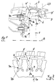
Zur näheren Erläuterung der Erfindung wird auf die beigefügten Prinzipskizzen
verwiesen, wobei in Fig. 1 ein Teil-Längsschnitt und in Fig. 2 eine Teil-Ansicht
eines bevorzugten Ausführungsbeispiels einer erfindungsgemäßen
Turbinen-Laufradscheibe gezeigt ist.
Fig. 3 dient der Erläuterung der physikalischen Zusammenhänge und zeigt
in einem Diagramm die Spannungskonzentration (aufgetragen auf der Ordinate)
als Funktion des auf der Abszisse aufgetragenen dimensionslosen
Lochabstandes P/D bei einer Reihenanordnung von Löchern mit dem
Durchmesser D, die um das Maß P voneinander beabstandet sind.For a more detailed explanation of the invention, reference is made to the attached schematic diagrams, a partial longitudinal section being shown in FIG. 1 and a partial view of a preferred exemplary embodiment of a turbine impeller disk according to the invention in FIG. 2.
Fig. 3 is used to explain the physical relationships and shows in a diagram the stress concentration (plotted on the ordinate) as a function of the dimensionless hole spacing P / D plotted on the abscissa for a row arrangement of holes with the diameter D, the dimension P from each other are spaced.
In den Fig. 1, 2 ist mit der Bezugsziffer 1 eine Laufradscheibe insbesondere
einer Gasturbine bezeichnet, die an ihrem Außenumfang wie üblich eine
Vielzahl von jeweils ein Tannenbaumprofil aufweisenden Scheibennuten 2
besitzt, in welche jeweils eine Turbinenschaufel 3 eingesetzt ist. Jede Turbinenschaufel
3 ist luftgekühlt, d. h. in jeder Turbinenschaufel 3 sind nicht
dargestellte Kühlluftkanäle vorgesehen, in welche von der Scheibennut 2
aus ein Kühlluftstrom eintreten kann.1, 2 with the
In jede Scheibennut 2 gelangt dieser Kühlluftstrom über zumindest zwei
Kühlluftkanäle 4, die von der Scheibenstirnseite 1a ausgehen - die entsprechende
Mündungsöffnung ist mit der Bezugsziffer 7b bezeichnet - und im
Inneren der Scheibe zur jeweiligen Scheibennut 2 geführt sind, wo sie im
Nutengrund 2a münden ( Mündungsöffnung 7a ). Es liegt auf der Hand, daß
über zumindest zwei Kühlluftkanäle 4, die von der gleichen Scheibenstirnseite
1a ausgehen, und die jeweils eine gewisse Querschnittsfläche Q besitzen,
ein betragsmäßig größerer Kühlluftstrom herangeführt werden kann, als über
einen einzigen Kühlluftkanal 4 mit der gleichen Querschnittsfläche Q, wie
dies im Stand der Technik bekannt und üblich ist. Zwar wäre es grundsätzlich
auch möglich, einen einzigen Kühlluftkanal 4 mit einer dementsprechend
größeren Querschnittsfläche (beispielsweise 2 x Q) vorzusehen, jedoch
würde die dementsprechend größere Mündungsöffnung 7a eines derart großen
Kühlluftkanales im Nutengrund 2a erhebliche Spannungsspitzen hervorrufen,
die größer sind als die von den Mündungsöffnungen 7a zweier dementsprechend
kleinerer Kühlluftkanäle 4 hervorgerufenen Spannungsspitzen.This cooling air flow passes into each
Die entsprechenden physikalisch-theoretischen Zusammenhänge seien kurz
anahnd von Fig. 3 erläutert:
Gezeigt ist zunächst die Aufsicht auf ein Bauteil 10, in welchem eine Reihe
von Löchern 11, die jeweils den Durchmesser D besitzen, vorgesehen ist.
Die einzelnen Löcher 11 sind dabei um daß Maß P voneinander beabstandet.
Die Hauptspannungsrichtung längs der Reihe von Löchern 11 ist durch
den Pfeil 12 dargestellt. Im Diagramm nach Fig. 3 ist nun der Spannungskonzentrationsfaktor
auf der Ordinate und auf der Abszisse der dimensionslose
Lochabstand P/D aufgetragen. The corresponding physical-theoretical relationships are briefly explained in FIG. 3:
First of all, the view of a
Man erkennt, daß der Spannungskonzentrationsfaktor mit abnehmendem
dimensionslosem Lochabstand P/D ebenfalls geringer wird.
Durch die erfindungsgemäße Aufteilung der Querschnittsfläche Q auf die
doppelte Anzahl von Bohrungen 7a in den Fig. 1,2 reduziert sich der Parameter
P/D gemäß Fig. 3 auf das 0,707-fache seine ursprünglichen Wertes,
so daß hierdurch auch der Spannungskonzentrationsfaktor entsprechend
abnimmt.
Zusätzlich kann aus der örtlichen Verlagerung der Spannungsspitzen Nutzen
gezogen werden, da die Orte der relativen Spannungsmaxima der Luftlöcher
und der Scheibennuten in Umfangsrichtung nun nicht mehr zusammenfallen.
Somit kann die sich aus der (potentialtheoretischen) Superpositionierung der
einzelnen Spannungsfelder um Bohrung und Nut ergebende absolute Spitzenspannung
in erheblichem Umfang reduziert werden, was im Hinblick auf
die Dauerfestigkeit einer Turbinenlaufscheibe anzustreben ist.It can be seen that the stress concentration factor also decreases as the dimensionless hole spacing P / D decreases.
By dividing the cross-sectional area Q according to the invention into twice the number of
In addition, use can be made of the local displacement of the stress peaks since the locations of the relative stress maxima of the air holes and the disk grooves no longer coincide in the circumferential direction.
Thus, the absolute peak stress resulting from the (potential theoretical) superposition of the individual stress fields around the bore and groove can be reduced to a considerable extent, which is desirable in view of the fatigue strength of a turbine disk.
Zurückkommend auf die konstruktive Ausführung der Erfindung ergibt sich
eine hinsichtlich der Größe des erzielbaren Kühlluftstromes sowie im Hinblick
auf die Schwächung der Laufradscheibe 1 durch die Kühlluftkanäle 4
günstige Kühlluftkanal-Anordnung, wenn in jeder Scheibennut 2 die Mündungsöffnungen
7a der beiden Kühlluftkanäle 4 im wesentlichen in einer
gemeinsamen zur Scheibenachse senkrechten Schnittebene nebeneinander
liegen. Dabei ist es vorteilhaft, wenn - wie die Teil-Ansicht auf die Scheibenstirnseite
1a in Fig. 2 zeigt - für jede Scheibennut 2 die beiden Kühlluftkanäle
4 im wesentlichen spiegelbildlich zu sowie geneigt gegenüber einer
in radialer Richtung von der nicht gezeigten Scheibenachse zur Mitte der
Scheibennut 2 führenden Symmetrieebene 5 vorgesehen sind. Dabei können
die Längsachsen sämtlicher Kühlluftkanäle 4 linear oder beliebig gebogen
verlaufen, ebenso kann der Querschnitt dieser Kühlluftkanäle kreisförmig
oder elliptisch oder sonstwie geeignet geformt sein. Returning to the constructive embodiment of the invention, it follows
one with regard to the size of the achievable cooling air flow and with regard
on the weakening of the
Wie bereits eingangs erwähnt, kann ein Teil des in die Scheibennuten 2 dieser
Laufradscheibe eingebrachten Kühlluftstromes dazu genutzt werden,
eine dieser ersten Laufradscheibe 1 nachgeschaltete zweite Laufradscheibe
(nicht gezeigt) mit Kühlluft zu versorgen. In den die Turbinenschaufeln 3 in
der Laufradscheibe 1 fixierenden Schließplatten 6 können im Bereich der
Scheibennuten 2 dementsprechende Durchtrittsöffnungen 9 für einen Teil-Kühlluftstrom
vorgesehen sein, die jeweils über einen im Fuß der Turbinenschaufel
vorgesehenen Kanal 9' mit einem sich an den Kühlluftkanal 4 anschließenden,
im Schaufelfuß vorgesehenen Kühlluftkanal 4' verbunden
sind.As already mentioned at the beginning, part of this can be inserted into the
Allgemein kann somit durch die hier gezeigte Verdopplung bzw. Vervielfachung
der in einer Scheibennut 2 mündenden Kühlluftkanäle 4 gegenüber
dem bekannten Stand der Technik ein deutlich größerer Kühlluftstrom zum
Fuß jeder Turbinenschaufel 3 geführt werden. Dabei führen die mehreren
Mündungsöffnungen 7a der mehreren Kühlluftkanäle 4 zu deutlich geringeren
mechanischen Belastungen der Laufradscheibe 1, als dies ein einziger
Kühlluftkanal mit einer dementsprechend großen Querschnittsfläche und
somit einer dementsprechend vergrößerten Mündungsöffnung 7a verursachen
würde. Selbstverständlich sind dabei eine Vielzahl von Abwandlungen
insbesondere konstruktiver Art vom gezeigten Ausführungsbeispiel möglich,
ohne den Inhalt der Patentansprüche zu verlassen.In general, the doubling or multiplication shown here
the
Claims (4)
dadurch gekennzeichnet, daß in jeder Scheibennut (2) zumindest zwei jeweils von der gleichen Scheibenstirnseite (1a) ausgehende Kühlluftkanäle (4) münden.Turbine impeller disk with cooling air channels (4) extending from the disk end face (1a), which open into the disk grooves (2) into which air-cooled turbine blades (3) are inserted,
characterized in that in each disc groove (2) at least two cooling air ducts (4) each emanating from the same disc end face (1a) open.
dadurch gekennzeichnet, daß in jeder Scheibennut (2) die Mündungsöffnungen (7a) zweier Kühlluftkanäle (4) im wesentlichen in einer gemeinsamen zur Scheibenachse (8) senkrechten Schnittebene nebeneinander liegen.Turbine impeller disk according to claim 1,
characterized in that in each disk groove (2) the orifices (7a) of two cooling air ducts (4) lie essentially next to one another in a common sectional plane perpendicular to the disk axis (8).
dadurch gekennzeichnet, daß für jede Scheibennut (2) zwei Kühlluftkanäle (4) im wesentlichen spiegelbildlich zu sowie geneigt gegenüber einer in radialer Richtung von der Scheibenachse (8) zur Mitte der Scheibennut (2) führenden Symmetrieebene (5) vorgesehen sind. Turbine impeller disk according to claim 1 or 2,
characterized in that for each disk groove (2) two cooling air ducts (4) are provided essentially mirror-inverted and inclined relative to a plane of symmetry (5) leading in the radial direction from the disk axis (8) to the center of the disk groove (2).
dadurch gekennzeichnet, daß der über einen der in jeder Scheibennut (2) mündenden Kühlluftkanäle (4) herangeführte Kühlluftstrom bevorzugt zur Kühlung einer zweiten dieser Turbinen-Laufradscheibe (1) nachgeordneten Turbinen-Laufradscheibe herangezogen wird.Turbine impeller disk according to one of the preceding claims,
characterized in that the cooling air flow led through one of the cooling air channels (4) opening into each disc groove (2) is preferably used for cooling a second turbine impeller disc downstream of this turbine impeller disc (1).
Applications Claiming Priority (2)
| Application Number | Priority Date | Filing Date | Title |
|---|---|---|---|
| DE19705442 | 1997-02-13 | ||
| DE19705442A DE19705442A1 (en) | 1997-02-13 | 1997-02-13 | Turbine impeller disk with cooling air channels |
Publications (2)
| Publication Number | Publication Date |
|---|---|
| EP0859128A1 true EP0859128A1 (en) | 1998-08-19 |
| EP0859128B1 EP0859128B1 (en) | 2000-04-05 |
Family
ID=7820090
Family Applications (1)
| Application Number | Title | Priority Date | Filing Date |
|---|---|---|---|
| EP98101046A Expired - Lifetime EP0859128B1 (en) | 1997-02-13 | 1998-01-22 | Turbine disc with cooling channels |
Country Status (3)
| Country | Link |
|---|---|
| US (1) | US6022190A (en) |
| EP (1) | EP0859128B1 (en) |
| DE (2) | DE19705442A1 (en) |
Cited By (3)
| Publication number | Priority date | Publication date | Assignee | Title |
|---|---|---|---|---|
| EP1004748A3 (en) * | 1998-11-27 | 2001-10-17 | Rolls-Royce Deutschland Ltd & Co KG | Rotor for a turbomachine |
| FR2987864A1 (en) * | 2012-03-12 | 2013-09-13 | Snecma | Turbomachine e.g. turboshaft engine, for aircraft, has radial air-guiding unit including ventilation opening placed between inlet and outlet for directing portion of air circulating in guiding unit along direction of downstream disk |
| US8708657B2 (en) | 2010-01-22 | 2014-04-29 | Rolls-Royce Plc | Rotor Disc |
Families Citing this family (25)
| Publication number | Priority date | Publication date | Assignee | Title |
|---|---|---|---|---|
| US6428270B1 (en) * | 2000-09-15 | 2002-08-06 | General Electric Company | Stage 3 bucket shank bypass holes and related method |
| US7465149B2 (en) * | 2006-03-14 | 2008-12-16 | Rolls-Royce Plc | Turbine engine cooling |
| EP1892375A1 (en) * | 2006-08-23 | 2008-02-27 | Siemens Aktiengesellschaft | Turbine engine rotor disc with cooling passage |
| US20090110561A1 (en) * | 2007-10-29 | 2009-04-30 | Honeywell International, Inc. | Turbine engine components, turbine engine assemblies, and methods of manufacturing turbine engine components |
| JP4939461B2 (en) * | 2008-02-27 | 2012-05-23 | 三菱重工業株式会社 | Turbine disc and gas turbine |
| JP4981709B2 (en) * | 2008-02-28 | 2012-07-25 | 三菱重工業株式会社 | Gas turbine, disk and method for forming radial passage of disk |
| DE102009007468A1 (en) * | 2009-02-04 | 2010-08-19 | Mtu Aero Engines Gmbh | Integrally bladed rotor disk for a turbine |
| US8087871B2 (en) * | 2009-05-28 | 2012-01-03 | General Electric Company | Turbomachine compressor wheel member |
| US8591180B2 (en) * | 2010-10-12 | 2013-11-26 | General Electric Company | Steam turbine nozzle assembly having flush apertures |
| FR2969209B1 (en) * | 2010-12-21 | 2019-06-21 | Safran Aircraft Engines | TURBINE STOVE FOR AIRCRAFT TURBOMACHINE HAVING IMPROVED SEAL BETWEEN THE FLASK AND THE TURBINE BLADES |
| US10683756B2 (en) | 2016-02-03 | 2020-06-16 | Dresser-Rand Company | System and method for cooling a fluidized catalytic cracking expander |
| US10519857B2 (en) | 2016-10-24 | 2019-12-31 | Rolls-Royce Corporation | Disk with lattice features adapted for use in gas turbine engines |
| US10458242B2 (en) * | 2016-10-25 | 2019-10-29 | Pratt & Whitney Canada Corp. | Rotor disc with passages |
| DE102016124806A1 (en) * | 2016-12-19 | 2018-06-21 | Rolls-Royce Deutschland Ltd & Co Kg | A turbine blade assembly for a gas turbine and method of providing sealing air in a turbine blade assembly |
| US10415403B2 (en) | 2017-01-13 | 2019-09-17 | Rolls-Royce North American Technologies Inc. | Cooled blisk for gas turbine engine |
| US10247015B2 (en) | 2017-01-13 | 2019-04-02 | Rolls-Royce Corporation | Cooled blisk with dual wall blades for gas turbine engine |
| US10934865B2 (en) | 2017-01-13 | 2021-03-02 | Rolls-Royce Corporation | Cooled single walled blisk for gas turbine engine |
| DE102017109952A1 (en) * | 2017-05-09 | 2018-11-15 | Rolls-Royce Deutschland Ltd & Co Kg | Rotor device of a turbomachine |
| CA3000376A1 (en) * | 2017-05-23 | 2018-11-23 | Rolls-Royce Corporation | Turbine shroud assembly having ceramic matrix composite track segments with metallic attachment features |
| KR102028804B1 (en) * | 2017-10-19 | 2019-10-04 | 두산중공업 주식회사 | Gas turbine disk |
| US10718218B2 (en) | 2018-03-05 | 2020-07-21 | Rolls-Royce North American Technologies Inc. | Turbine blisk with airfoil and rim cooling |
| CN109236378A (en) * | 2018-09-11 | 2019-01-18 | 上海发电设备成套设计研究院有限责任公司 | A kind of single stream high-temperature rotor for the high-parameter steam turbine that steam inside is cooling |
| KR102141626B1 (en) * | 2018-10-01 | 2020-08-05 | 두산중공업 주식회사 | Turbine apparatus |
| JP7328794B2 (en) * | 2019-05-24 | 2023-08-17 | 三菱重工業株式会社 | Rotor discs, rotor shafts, turbine rotors, and gas turbines |
| US11506060B1 (en) | 2021-07-15 | 2022-11-22 | Honeywell International Inc. | Radial turbine rotor for gas turbine engine |
Citations (4)
| Publication number | Priority date | Publication date | Assignee | Title |
|---|---|---|---|---|
| GB2065788A (en) * | 1979-12-17 | 1981-07-01 | United Technologies Corp | Rotor disc cooling air duct |
| DE3444586A1 (en) | 1983-12-22 | 1985-07-04 | United Technologies Corp., Hartford, Conn. | WHEEL ARRANGEMENT IN A GAS TURBINE |
| DE2947521A1 (en) | 1978-11-27 | 1986-06-26 | Snecma | TURBINE DISC WITH CHANNELS FOR THE TRANSFER OF A COOLING FLUID |
| DE4428207A1 (en) * | 1994-08-09 | 1996-02-15 | Bmw Rolls Royce Gmbh | Mfg. turbine rotor disc with curved cooling air channels |
Family Cites Families (11)
| Publication number | Priority date | Publication date | Assignee | Title |
|---|---|---|---|---|
| US3849025A (en) * | 1973-03-28 | 1974-11-19 | Gen Electric | Serpentine cooling channel construction for open-circuit liquid cooled turbine buckets |
| US4275990A (en) * | 1977-12-17 | 1981-06-30 | Rolls-Royce Limited | Disc channel for cooling rotor blade roots |
| US4212587A (en) * | 1978-05-30 | 1980-07-15 | General Electric Company | Cooling system for a gas turbine using V-shaped notch weirs |
| US4626169A (en) * | 1983-12-13 | 1986-12-02 | United Technologies Corporation | Seal means for a blade attachment slot of a rotor assembly |
| GB2251897B (en) * | 1991-01-15 | 1994-11-30 | Rolls Royce Plc | A rotor |
| US5816777A (en) * | 1991-11-29 | 1998-10-06 | United Technologies Corporation | Turbine blade cooling |
| US5318404A (en) * | 1992-12-30 | 1994-06-07 | General Electric Company | Steam transfer arrangement for turbine bucket cooling |
| US5593274A (en) * | 1995-03-31 | 1997-01-14 | General Electric Co. | Closed or open circuit cooling of turbine rotor components |
| JP3448145B2 (en) * | 1995-11-24 | 2003-09-16 | 三菱重工業株式会社 | Heat recovery type gas turbine rotor |
| US5800124A (en) * | 1996-04-12 | 1998-09-01 | United Technologies Corporation | Cooled rotor assembly for a turbine engine |
| US5755556A (en) * | 1996-05-17 | 1998-05-26 | Westinghouse Electric Corporation | Turbomachine rotor with improved cooling |
-
1997
- 1997-02-13 DE DE19705442A patent/DE19705442A1/en not_active Withdrawn
-
1998
- 1998-01-22 DE DE59800115T patent/DE59800115D1/en not_active Expired - Fee Related
- 1998-01-22 EP EP98101046A patent/EP0859128B1/en not_active Expired - Lifetime
- 1998-02-06 US US09/019,812 patent/US6022190A/en not_active Expired - Lifetime
Patent Citations (4)
| Publication number | Priority date | Publication date | Assignee | Title |
|---|---|---|---|---|
| DE2947521A1 (en) | 1978-11-27 | 1986-06-26 | Snecma | TURBINE DISC WITH CHANNELS FOR THE TRANSFER OF A COOLING FLUID |
| GB2065788A (en) * | 1979-12-17 | 1981-07-01 | United Technologies Corp | Rotor disc cooling air duct |
| DE3444586A1 (en) | 1983-12-22 | 1985-07-04 | United Technologies Corp., Hartford, Conn. | WHEEL ARRANGEMENT IN A GAS TURBINE |
| DE4428207A1 (en) * | 1994-08-09 | 1996-02-15 | Bmw Rolls Royce Gmbh | Mfg. turbine rotor disc with curved cooling air channels |
Cited By (3)
| Publication number | Priority date | Publication date | Assignee | Title |
|---|---|---|---|---|
| EP1004748A3 (en) * | 1998-11-27 | 2001-10-17 | Rolls-Royce Deutschland Ltd & Co KG | Rotor for a turbomachine |
| US8708657B2 (en) | 2010-01-22 | 2014-04-29 | Rolls-Royce Plc | Rotor Disc |
| FR2987864A1 (en) * | 2012-03-12 | 2013-09-13 | Snecma | Turbomachine e.g. turboshaft engine, for aircraft, has radial air-guiding unit including ventilation opening placed between inlet and outlet for directing portion of air circulating in guiding unit along direction of downstream disk |
Also Published As
| Publication number | Publication date |
|---|---|
| US6022190A (en) | 2000-02-08 |
| DE19705442A1 (en) | 1998-08-20 |
| DE59800115D1 (en) | 2000-05-11 |
| EP0859128B1 (en) | 2000-04-05 |
Similar Documents
| Publication | Publication Date | Title |
|---|---|---|
| EP0859128B1 (en) | Turbine disc with cooling channels | |
| EP0621920B1 (en) | Cooling of the shroud of a turbine blade | |
| EP1223308B1 (en) | Turbomachine component | |
| DE10022715B4 (en) | Ball screw | |
| EP1201879B1 (en) | Cooled component, casting core and method for the manufacture of the same | |
| DE1928184A1 (en) | Fastening and cooling arrangement for rotor blade rims of turbo machines, preferably gas turbines | |
| EP1113145A1 (en) | Blade for gas turbines with metering section at the trailing edge | |
| DE10064264B4 (en) | Arrangement for cooling a component | |
| DE2241194A1 (en) | FLOW MACHINE SHOVEL WITH A WING-SHAPED CROSS-SECTIONAL PROFILE AND WITH A NUMBER OF COOLING DUCTS RUNNING IN THE LENGTH DIRECTION OF THE SHOVEL | |
| EP0859127A1 (en) | Channeling of cooling air in a turbine rotor disc | |
| WO2014173601A1 (en) | Electric machine having an improved cooling of the winding head | |
| EP2520396A1 (en) | Coolant supply | |
| DE4434751A1 (en) | Ball cover | |
| EP1806168A1 (en) | Steam strainer | |
| DE4332693C2 (en) | Ventilated brake disc | |
| DE2739431B2 (en) | Air-directing comb for a jet loom | |
| DE1964195B2 (en) | Air injection device | |
| EP3401503A1 (en) | Rotor of a turbomachine | |
| DE3504343A1 (en) | Saw blade | |
| DD297226A5 (en) | INDUKTIVDURCHLASS | |
| DE102020205812A1 (en) | Clamping device for positioning copper rods | |
| DE2638334B2 (en) | Exhaust system for an internal combustion engine | |
| DE2345810C2 (en) | Device for cooling the stator teeth of electrical machines | |
| DE102006020489A1 (en) | Bolt circle offset screw or nut and method for its production | |
| DE102004036389B4 (en) | Turbine blade root with multiple radius groove for axial blade attachment |
Legal Events
| Date | Code | Title | Description |
|---|---|---|---|
| PUAI | Public reference made under article 153(3) epc to a published international application that has entered the european phase |
Free format text: ORIGINAL CODE: 0009012 |
|
| AK | Designated contracting states |
Kind code of ref document: A1 Designated state(s): DE FR GB |
|
| AX | Request for extension of the european patent |
Free format text: AL;LT;LV;MK;RO;SI |
|
| 17P | Request for examination filed |
Effective date: 19980915 |
|
| AKX | Designation fees paid |
Free format text: DE FR GB |
|
| RBV | Designated contracting states (corrected) |
Designated state(s): DE FR GB |
|
| 17Q | First examination report despatched |
Effective date: 19990521 |
|
| GRAG | Despatch of communication of intention to grant |
Free format text: ORIGINAL CODE: EPIDOS AGRA |
|
| GRAG | Despatch of communication of intention to grant |
Free format text: ORIGINAL CODE: EPIDOS AGRA |
|
| GRAH | Despatch of communication of intention to grant a patent |
Free format text: ORIGINAL CODE: EPIDOS IGRA |
|
| GRAH | Despatch of communication of intention to grant a patent |
Free format text: ORIGINAL CODE: EPIDOS IGRA |
|
| GRAA | (expected) grant |
Free format text: ORIGINAL CODE: 0009210 |
|
| AK | Designated contracting states |
Kind code of ref document: B1 Designated state(s): DE FR GB |
|
| RAP2 | Party data changed (patent owner data changed or rights of a patent transferred) |
Owner name: ROLLS-ROYCE DEUTSCHLAND GMBH |
|
| REF | Corresponds to: |
Ref document number: 59800115 Country of ref document: DE Date of ref document: 20000511 |
|
| RAP2 | Party data changed (patent owner data changed or rights of a patent transferred) |
Owner name: ROLLS-ROYCE DEUTSCHLAND GMBH |
|
| GBT | Gb: translation of ep patent filed (gb section 77(6)(a)/1977) |
Effective date: 20000504 |
|
| ET | Fr: translation filed | ||
| REG | Reference to a national code |
Ref country code: FR Ref legal event code: CD Ref country code: FR Ref legal event code: CA |
|
| PLBE | No opposition filed within time limit |
Free format text: ORIGINAL CODE: 0009261 |
|
| STAA | Information on the status of an ep patent application or granted ep patent |
Free format text: STATUS: NO OPPOSITION FILED WITHIN TIME LIMIT |
|
| 26N | No opposition filed | ||
| RAP2 | Party data changed (patent owner data changed or rights of a patent transferred) |
Owner name: ROLLS-ROYCE DEUTSCHLAND LTD & CO KG |
|
| REG | Reference to a national code |
Ref country code: FR Ref legal event code: CJ Ref country code: FR Ref legal event code: CA |
|
| REG | Reference to a national code |
Ref country code: GB Ref legal event code: IF02 |
|
| PGFP | Annual fee paid to national office [announced via postgrant information from national office to epo] |
Ref country code: DE Payment date: 20090302 Year of fee payment: 12 |
|
| PGFP | Annual fee paid to national office [announced via postgrant information from national office to epo] |
Ref country code: GB Payment date: 20090129 Year of fee payment: 12 |
|
| PGFP | Annual fee paid to national office [announced via postgrant information from national office to epo] |
Ref country code: FR Payment date: 20090119 Year of fee payment: 12 |
|
| GBPC | Gb: european patent ceased through non-payment of renewal fee |
Effective date: 20100122 |
|
| REG | Reference to a national code |
Ref country code: FR Ref legal event code: ST Effective date: 20100930 |
|
| PG25 | Lapsed in a contracting state [announced via postgrant information from national office to epo] |
Ref country code: FR Free format text: LAPSE BECAUSE OF NON-PAYMENT OF DUE FEES Effective date: 20100201 |
|
| PG25 | Lapsed in a contracting state [announced via postgrant information from national office to epo] |
Ref country code: DE Free format text: LAPSE BECAUSE OF NON-PAYMENT OF DUE FEES Effective date: 20100803 |
|
| PG25 | Lapsed in a contracting state [announced via postgrant information from national office to epo] |
Ref country code: GB Free format text: LAPSE BECAUSE OF NON-PAYMENT OF DUE FEES Effective date: 20100122 |