EP0859090A1 - Slide fitting for wall shower rod - Google Patents
Slide fitting for wall shower rod Download PDFInfo
- Publication number
- EP0859090A1 EP0859090A1 EP98101577A EP98101577A EP0859090A1 EP 0859090 A1 EP0859090 A1 EP 0859090A1 EP 98101577 A EP98101577 A EP 98101577A EP 98101577 A EP98101577 A EP 98101577A EP 0859090 A1 EP0859090 A1 EP 0859090A1
- Authority
- EP
- European Patent Office
- Prior art keywords
- bore
- slider according
- wall bar
- slider
- support body
- Prior art date
- Legal status (The legal status is an assumption and is not a legal conclusion. Google has not performed a legal analysis and makes no representation as to the accuracy of the status listed.)
- Granted
Links
- 210000002105 tongue Anatomy 0.000 claims description 6
- 230000015572 biosynthetic process Effects 0.000 claims 3
- 239000011324 bead Substances 0.000 description 2
- 230000003014 reinforcing effect Effects 0.000 description 2
- 238000004140 cleaning Methods 0.000 description 1
- 238000006073 displacement reaction Methods 0.000 description 1
- 230000000694 effects Effects 0.000 description 1
- 239000013013 elastic material Substances 0.000 description 1
- 230000002349 favourable effect Effects 0.000 description 1
- 238000001746 injection moulding Methods 0.000 description 1
- 238000009434 installation Methods 0.000 description 1
- 230000036316 preload Effects 0.000 description 1
- 239000000344 soap Substances 0.000 description 1
- 230000009870 specific binding Effects 0.000 description 1
- 230000007704 transition Effects 0.000 description 1
- XLYOFNOQVPJJNP-UHFFFAOYSA-N water Substances O XLYOFNOQVPJJNP-UHFFFAOYSA-N 0.000 description 1
Images


Classifications
-
- E—FIXED CONSTRUCTIONS
- E03—WATER SUPPLY; SEWERAGE
- E03C—DOMESTIC PLUMBING INSTALLATIONS FOR FRESH WATER OR WASTE WATER; SINKS
- E03C1/00—Domestic plumbing installations for fresh water or waste water; Sinks
- E03C1/02—Plumbing installations for fresh water
- E03C1/06—Devices for suspending or supporting the supply pipe or supply hose of a shower-bath
- E03C1/066—Devices for suspending or supporting the supply pipe or supply hose of a shower-bath allowing height adjustment of shower head
-
- E—FIXED CONSTRUCTIONS
- E03—WATER SUPPLY; SEWERAGE
- E03C—DOMESTIC PLUMBING INSTALLATIONS FOR FRESH WATER OR WASTE WATER; SINKS
- E03C1/00—Domestic plumbing installations for fresh water or waste water; Sinks
- E03C1/02—Plumbing installations for fresh water
- E03C1/06—Devices for suspending or supporting the supply pipe or supply hose of a shower-bath
Definitions
- the invention relates to a slider with a device for holding a hand shower, which is arranged with a continuous recess on a wall bar with a circular cross section and is adjustable in its height and rotational position.
- a device for holding a hand shower which is arranged with a continuous recess on a wall bar with a circular cross section and is adjustable in its height and rotational position.
- a device for holding a hand shower which is arranged with a continuous recess on a wall bar with a circular cross section and is adjustable in its height and rotational position.
- a device is known from German Patent 23 42 613.
- the slider is provided with slotted, ring-shaped clamping pieces that surround the wall bar. The two clamping pieces are each pressed by a spring against an inner cone of the sliding piece, so that the sliding piece is locked in the respective position on the wall bar. If the slider is to be moved on the wall bar, at least one clamping ring must be pressed into the slider in the desired direction of displacement against the force of the spring
- a sliding block for a wall bar of approximately rectangular cross section from German utility model 75 21 122, in which a clamping insert made of elastic material with a high coefficient of friction is used.
- a spherical holding head is provided for receiving the hand shower, which has a conical bore with a mouth-like opening.
- the holding head is pivotally held by two shell halves, locking teeth being formed on the end faces of the bearing journals, so that when the holding head is pivoted, the shell halves are deflected elastically and resiliently by the end teeth.
- a slide for a wall bar for receiving a hand shower is known, in which a brake pad made of rubber or plastic is provided between a wall bar of approximately triangular cross section and the slide. To increase the braking effect, it is also proposed to provide a pressure spring on the rear of the brake pad.
- the invention has for its object in the preamble to improve the specified slide of claim 1, so that a largely constant operational safety with easy adjustment of the Holding device is guaranteed.
- it belongs with the task of training the slider so that the Outdoor area designed in a tasteful way can be.
- a support body which has a conical bore on one end area with a mouth-like axial slot for receiving the hand shower and on the other end area a hole for the implementation of the wall rod, with the wall of the hole in one Half one or more rib-shaped projection (s) is or are formed, while in the opposite half of the bore an elastic tensioning element is provided which projects into the bore and the wall bar with a certain force against the rib-shaped projection or the rib-shaped projections presses.
- a support body can be provided without special unlocking buttons, in which on the one hand the storage option for the hand shower is formed and on the other hand in the receiving bore for the wall bar the rib-shaped projections with the tensioning element on the required certain stiffness when moving the slider the wall bar in a simple way. Due to this arrangement, the surface pressure of the projections to the wall bar is approximately linear, so that any water or soap residues located on the wall bar cannot essentially settle between the wall bar and the projections, which impair the required certain stiffness of the slider on the wall bar could. Further refinements of the invention are specified in claims 2 to 20.
- the tensioning element can be designed to be sensitive to the wall rod with simple means in terms of the pressure force that can be generated.
- the supporting body with its individual functional elements can advantageously be provided with an aesthetically appealing decorative cover.
- the decorative cover is expediently formed in two parts, namely by a front sleeve and a bracket piece essentially covering the rear area.
- the tapered bore with the mouth-like axial slot can expediently be formed in a spherical body which is pivotable, for. B. by 40 °, is received by a fork of the support body.
- a locking element can be arranged in the support body for the finely graduated pivoting, which is pressed by a spring against a toothing or incisions formed on the surface of the spherical body.
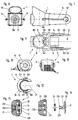
- the shower wall bar shown in FIGS. 1 to 3 is formed by a wall bar 6 and a slider which is rotatable and axially displaceably arranged on the wall bar 6 and which is provided with a decorative cover 5.
- the wall bar is arranged with brackets - not shown in the drawing - on a building wall at a distance approximately perpendicular.
- the wall bar 6 is designed as a tube with a circular cross section.
- the slider is formed by a support body 1, a clamping element 2, a spherical body 3, a locking element 4 and a decorative cover 5, consisting of a front sleeve 50 and a bracket piece 51.
- a continuous bore 10 is provided in the support body 1 at one end area, on the wall of which in one half two protrusions 11 running at a distance from one another parallel to the central axis 100 are formed in one piece with the support body 1, as shown in particular in FIGS. 3, 5 , 6 and 9 can be seen.
- the projections 11 are placed at an angle 110 of approximately 60 ° in one half of the bore 10 and protrude approximately 0.1 to 1.5 mm, preferably 0.5 mm, radially in the bore 10.
- the tensioning element 2 is provided opposite the two projections 11 in the other half of the bore 10.
- the clamping element 2 as can be seen in particular from FIGS. 13 and 14, is formed by an adjusting screw 23 which is held in the support body 1 by means of thread 230.
- a circular disk 20 with a guide pin 22 is received in a central bore 231 of the set screw 23.
- the guide pin 22 has snap tongues 220 on its front area so that the circular disk 20 is axially locked in the set position in the set screw 23.
- a rubber-elastic ring 24 is arranged as a spring on the guide pin 22.
- a hexagon socket 232 is formed in the area of the central bore 231 for the attachment of a turning tool.
- the circular disc 20 is provided with a protruding, arched end face 21, so that a precise contact with the wall bar 6 is ensured.
- the support body 1 is provided with a fork 12, between whose two arms 120 the spherical body 3 is arranged, as can be seen in particular from FIGS. 5 and 6 of the drawing.
- a tubular extension 13 is formed on the support body 1, in which the locking element 4 is arranged.
- a further inner axial guide 130 is formed coaxially in the extension 13, as can be seen in particular from FIG. 8 of the drawing, which ensures a non-rotatable axial guide of the latching element 4.
- the support body 1 in the region of the outside of the arms 120 each has a holding rail 14, as can be seen in particular from FIGS. 7, 8 and 9.
- a resilient snap tongue 140 is formed, with which the front sleeve 15 which can be pushed onto the holding rails 14 is locked in the inserted position.
- the support body 1 is advantageously made in one piece from a suitable plastic by injection molding.
- Ball body 3 has a tapered bore 30 an axial slot 31 for receiving one in the Drawing not shown hand shower with a corresponding Cone piece and hose line.
- the spherical body 3 is perpendicular to the axis of the taper bore with two diametrically opposed bearing journals 32, as is shown in particular in FIGS. 10, 11 and 12 can be seen.
- Bearing pin 32 has a radially projecting nose 320, with which in the installation position is prevented the arms 120 of the fork 12 can spread undesirably.
- the spherical body 3 are in the manner of a toothing rounded incisions 33 for attacking the locking element 4 trained.
- the locking element 4 consists of a plate-shaped collar 41, on the one hand a guide pin 42 with a polygonal profile for rotationally secure reception in the axial guide 130 and on the other hand a wedge piece 43 for engaging in the incisions 33 on the spherical body.
- a spring 40 is arranged between the inner axial guide 130 and the tubular extension 13, which is supported on the one hand in the base of the support body 1 and on the other hand on the collar 41 and thus the wedge piece 43 against the Shell surface of the spherical body 3 presses.
- the spherical body 3 with its bearing pins 32 is pressed radially out of the fork 12 of the supporting body 1, so that the protruding nose 320 in each case engages over an arm 120 on the outer surface.
- the protruding lugs 320 engage in a recess on the outer sides of the two arms 120.
- the lugs with the bearing pins can also be designed so that a special depression on the outside of the arms 120 is not necessary.
- the ball body 3 is thus only supported in the front half of the bearing bores 121 in the arms 120.
- the bearing pins 32 are reliably guided in the bearing bores 121 by the compressive force of the spring 40.
- a rotatable roller can also be arranged on the collar 41 with the aid of support bearings 440, as can be seen from FIGS. 18 to 20 of the drawing.
- the rotatably arranged roller enables extremely low-wear operation of the locking element in connection with the spherical body.
- the decorative cover 5 formed from the front sleeve 50 and the bracket piece 51 primarily serves for the shapely exterior design and the easy cleaning of the sliding piece.
- the front sleeve 50 is provided with two opposing openings 502, into which the snap tongues 140 partially enclose.
- Guide rails 501 are also integrally formed on the inner sides of the front sleeve 15 for guidance on the holding rails 14.
- latching lugs 510 are formed on the two side arms, which in the plug-in position encompass the rest of the openings 502, as can be seen in particular from FIG. 4.
- the front sleeve 50 also has recesses 500 which, on the one hand, allow the wall rod 6 to pass through and, on the other hand, allow the hand shower connected to a hose to be stored in the various pivoting positions of the spherical body 3.
- the bracket piece 51 also has the opening 511 on the rear, through which a rotary tool for adjusting the clamping element 2 can be inserted.
- the bracket piece 51 has a reinforcing rib 512 with plug stops 513.
- a slightly protruding bead 503 is also formed on both sides to enable a harmonious transition to the bracket piece 51.
- the slider described above can be assembled in the following way: First, the clamping element 2, which has been joined together to form a structural unit, is screwed into the provided threaded bore in the supporting body 1 with the thread 230, and then the locking element 4 with the spring 40 is pushed into the shoulder 13. Then the spherical body 3 is inserted laterally into the fork 12 with the bearing journal 32.
- the bearing pins 32 here have inclined surfaces 321, so that the fork 12 is elastically expanded in the region of the arms 120. On both sides of the arms 120, the stop ribs 122 come into the region of the pivot stop recess 34 of the spherical body 3.
- the arms 120 spring back into the original position, after the spherical body 3 has been released by the spring 40 the wedge piece 43 is pushed out of the fork 12 again by a short distance, so that the lugs 320 on the outside engage behind the arms 120 and rule out undesired spreading of the fork 12.
- the spherical body 3 can then be pivoted in the frame of the pivot stop recess 34 around the axis of the bearing journal 32 by an angle of approximately 40 °, the wedge piece 43 engaging in the notch 33 belonging to the selected pivot position and preventing unintentional pivoting. Then the front sleeve 50 can be pushed onto the support body 1 from the fork side.
- the guide rails 501 formed on the sides of the front sleeve 50 reach the holding rails 14 formed laterally on the supporting body 1.
- the snap tongues 140 are deflected in order to spring back into the openings 502 after reaching the plug position and to close the front sleeve 50 in the plug position lock. Then the bracket piece 51 can be pushed onto the support body 1 from behind.
- the two arms of the bracket piece 51 are first expanded slightly elastically because of the locking lugs 510, in order to then snap into a remaining area of the openings 502 of the front sleeve 50 in the plug-in position, the plug stops 513 of the reinforcing rib 512 on the front side at the same time in front of the openings 502 of the front sleeve 20 get to the plant.
- the openings 502 are completely covered to the outside by the bracket piece 51.
- the end regions of the bracket piece 51 lie on the end face against the bead 503 formed on the front sleeve 51 and thus close off the front sleeve 50 in the rear region.
- the slide is completely assembled and can be pushed axially onto a wall bar 6 as a structural unit.
- a turning tool can be introduced into the clamping element 2 through the opening 511.
- the contact pressure can then be precisely adjusted with a rotary movement of the tensioning element 2.
- the thread 230 is designed as a fine thread, so that a sensitive and precise setting and contact pressure is made possible. Then the slider is ready for use.
- the radial preload being set so that on the one hand the slide 1 can be easily moved by hand on the wall bar 6 and on the other hand in the desired positions on the wall bar 6 remains securely.
- the required stiffness of the slider subsides, the required stiffness can be easily restored by adjusting the tensioning element 2.
Abstract
Bei einem Gleitstück mit einer Einrichtung zur Halterung einer Handbrause, welches mit einer durchgehenden Aussparung auf einer Wandstange mit kreisförmigem Querschnitt angeordnet und in seiner Höhen- und Drehlage verstellbar ist, ist zur Verbesserung vorgeschlagen, daß ein Tragkörper (1) vorgesehen ist, der an dem einen Endbereich eine Kegelbohrung (30) mit einem maulartigen Axialschlitz (31) zur Aufnahme der Handbrause und am anderen Endbereich eine Bohrung (10) für die Durchführung der Wandstange hat, wobei an der Wandung der Bohrung in der einen Hälfte ein oder mehrere rippenförmige(r) Vorsprüng(e) (11) ausgebildet ist oder sind, während an der gegenüberliegenden Hälfte der Bohrung ein elastisches Spannelement (2) vorgesehen ist, welches in die Bohrung hineinragt und die Wandstange mit einer bestimmten Kraft gegen den rippenförmigen Vorsprung oder die rippenförmigen Vorsprünge drückt. <IMAGE>In a slider with a device for holding a hand shower, which is arranged with a continuous recess on a wall bar with a circular cross-section and adjustable in its height and rotational position, it is proposed to improve that a support body (1) is provided, which on the one end region has a tapered bore (30) with a mouth-like axial slot (31) for receiving the hand shower and at the other end region a bore (10) for the passage of the wall rod, one or more rib-shaped (r ) Projection (s) (11) is or are formed, while on the opposite half of the bore an elastic clamping element (2) is provided, which protrudes into the bore and presses the wall bar with a certain force against the rib-shaped projection or the rib-shaped projections . <IMAGE>
Description
Die Erfindung betrifft ein Gleitstück mit einer Einrichtung
zur Halterung einer Handbrause, welches mit
einer durchgehenden Aussparung auf einer Wandstange mit
kreisförmigem Querschnitt angeordnet und in seiner Höhen- und Drehlage verstellbar ist.
Eine derartige Einrichtung ist aus der deutschen Patentschrift
23 42 613 bekannt. Das Gleitstück ist hierbei
mit geschlitzten, ringförmigen Klemmstücken versehen,
die die Wandstange umfassen. Die beiden Klemmstükke
werden dabei von einer Feder jeweils gegen einen Innenkegel
des Gleitstucks gedrückt, so daß das Gleitstück
in der jeweiligen Lage auf der Wandstange arretiert
wird. Soll das Gleitstück auf der Wandstange verschoben
werden, so muß wenigstens ein Klemmring in die
gewünschte Verschieberichtung entgegen der Kraft der
Feder in das Gleitstück hineingedruckt werden. Außerdem
ist an dem Gleitstück ein dornartiger Zapfen ausgebildet,
auf den eine Handbrause mit einer entsprechenden
Aufnahmeöffnung aufsteckbar ist. The invention relates to a slider with a device for holding a hand shower, which is arranged with a continuous recess on a wall bar with a circular cross section and is adjustable in its height and rotational position.
Such a device is known from
Ferner ist für eine im Querschnitt etwa rechteckig ausgebildete
Wandstange aus dem deutschen Gebrauchsmuster
75 21 122 ein Gleitstück bekannt, bei dem ein Klemmeinsatz
aus elastischem Material mit hohem Reibungskoeffizienten
eingesetzt ist. Für die Aufnahme der Handbrause
ist hierbei ein kugelförmiger Haltekopf vorgesehen, der
eine konische Bohrung mit einer maulartigen Öffnung
aufweist. Der Haltekopf ist von zwei Schalenhälften
verschwenkbar gehalten, wobei an den Stirnseiten der
Lagerzapfen Rastverzahnungen ausgebildet sind, so daß
bei einem Verschwenken des Haltekopfes die Schalenhälften
von den Stirnverzahnungen elastisch federnd ausgelenkt
werden.
Außerdem ist aus dem deutschen Gebrauchsmuster 18 39
393 ein Gleitstück für eine Wandstange zur Aufnahme einer
Handbrause bekannt, bei dem zwischen einer im Querschnitt
etwa dreieckig ausgebildeten Wandstange und dem
Gleitstück eine Bremsauflage aus Gummi oder Kunststoff
vorgesehen ist. Hierbei ist zur Erhöhung der Bremswirkung
außerdem vorgeschlagen, an der Rückseite der Bremsauflage
eine Andrückfeder vorzusehen.Furthermore, a sliding block is known for a wall bar of approximately rectangular cross section from German utility model 75 21 122, in which a clamping insert made of elastic material with a high coefficient of friction is used. A spherical holding head is provided for receiving the hand shower, which has a conical bore with a mouth-like opening. The holding head is pivotally held by two shell halves, locking teeth being formed on the end faces of the bearing journals, so that when the holding head is pivoted, the shell halves are deflected elastically and resiliently by the end teeth.
In addition, from German utility model 18 39 393 a slide for a wall bar for receiving a hand shower is known, in which a brake pad made of rubber or plastic is provided between a wall bar of approximately triangular cross section and the slide. To increase the braking effect, it is also proposed to provide a pressure spring on the rear of the brake pad.
Der Erfindung liegt die Aufgabe zugrunde, das im Oberbegriff
des Anspruchs 1 angegebene Gleitstück zu verbessern,
so daß eine weitgehend gleichbleibende Betriebssicherheit
bei einfacher Einstellmöglichkeit der
Halteeinrichtung gewährleistet ist. Hierbei gehört es
mit zur Aufgabe, das Gleitstück so auszubilden, daß der
Außenbereich in geschmacklich ansprechender Weise gestaltet
werden kann. The invention has for its object in the preamble
to improve the specified slide of
Diese Aufgabe wird erfindungsgemäß dadurch gelöst, daß
ein Tragkörper vorgesehen ist, der an dem einen Endbereich
eine Kegelbohrung mit einem maulartigen Axialschlitz
zur Aufnahme der Handbrause und am anderen Endbereich
eine Bohrung für die Durchführung der Wandstange
hat, wobei an der Wandung der Bohrung in der einen
Hälfte ein oder mehrere rippenförmige(r) Vorsprüng(e)
ausgebildet ist oder sind, während in der gegenüberliegenden
Hälfte der Bohrung ein elastisches Spannelement
vorgesehen ist, welches in die Bohrung hineinragt und
die Wandstange mit einer bestimmten Kraft gegen den
rippenförmigen Vorsprung oder die rippenförmigen Vorsprünge
drückt.
Mit dieser Ausbildung wird erreicht, daß ein Tragkörper
ohne besondere Entriegelungstasten vorgesehen werden
kann, in dem einerseits die Ablagemöglichkeit für die
Handbrause ausgebildet ist und andererseits in der Aufnahmebohrung
für die Wandstange die rippenförmigen Vorsprünge
mit dem Spannelement die erforderliche bestimmte
Schwergängigkeit bei der Bewegung des Gleitstücks
auf der Wandstange in einfacher Weise sicherstellen.
Aufgrund dieser Anordnung ist die Flächenpressung der
Vorsprünge zur Wandstange etwa linienförmig ausgebildet,
so daß sich evtl. an der Wandstange befindliche
Wasser- oder Seifenreste im wesentlichen nicht zwischen
der Wandstange und den Vorsprüngen absetzen können, die
die erforderliche bestimmte Schwergängigkeit des Gleitstücks
auf der Wandstange beeinträchtigen könnten.
Weitere Ausgestaltungen der Erfindung sind in den Ansprüchen
2 bis 20 angegeben. This object is achieved in that a support body is provided which has a conical bore on one end area with a mouth-like axial slot for receiving the hand shower and on the other end area a hole for the implementation of the wall rod, with the wall of the hole in one Half one or more rib-shaped projection (s) is or are formed, while in the opposite half of the bore an elastic tensioning element is provided which projects into the bore and the wall bar with a certain force against the rib-shaped projection or the rib-shaped projections presses.
With this design it is achieved that a support body can be provided without special unlocking buttons, in which on the one hand the storage option for the hand shower is formed and on the other hand in the receiving bore for the wall bar the rib-shaped projections with the tensioning element on the required certain stiffness when moving the slider the wall bar in a simple way. Due to this arrangement, the surface pressure of the projections to the wall bar is approximately linear, so that any water or soap residues located on the wall bar cannot essentially settle between the wall bar and the projections, which impair the required certain stiffness of the slider on the wall bar could.
Further refinements of the invention are specified in
In weiterer Ausgestaltung der Erfindung kann das Spannelement
hinsichtlich der erzeugbaren Druckkraft auf die
Wandstange mit einfachen Mitteln feinfühlig einstellbar
ausgebildet werden.
Vorteilhaft kann hierbei der Tragkörper mit seinen einzelnen
Funktionselementen mit einer ästhetisch ansprechenden
Dekorabdeckung versehen werden.
Zweckmäßig wird die Dekorabdeckung zweiteilig, nämlich
von einer Vorderhülse und einem im wesentlichen den
hinteren Bereich abdeckenden Bügelstück ausgebildet.
Die Kegelbohrung mit dem maulartigen Axialschlitz kann
zweckmäßig in einem Kugelkörper ausgebildet werden, der
verschwenkbar, z. B. um 40°, von einer Gabel des Tragkörpers
aufgenommen wird. Hierbei kann zur feingestuften
Verschwenkung in dem Tragkörper ein Rastelement angeordnet
werden, das von einer Feder gegen eine auf der
Oberfläche des Kugelkörpers ausgebildeten Verzahnung
bzw. Einschnitte gedrückt wird.In a further embodiment of the invention, the tensioning element can be designed to be sensitive to the wall rod with simple means in terms of the pressure force that can be generated.
The supporting body with its individual functional elements can advantageously be provided with an aesthetically appealing decorative cover.
The decorative cover is expediently formed in two parts, namely by a front sleeve and a bracket piece essentially covering the rear area.
The tapered bore with the mouth-like axial slot can expediently be formed in a spherical body which is pivotable, for. B. by 40 °, is received by a fork of the support body. In this case, a locking element can be arranged in the support body for the finely graduated pivoting, which is pressed by a spring against a toothing or incisions formed on the surface of the spherical body.
Ein Ausführungsbeispiel ist in der Zeichnung dargestellt und wird im folgenden näher beschrieben. Es zeigt
- Fig. 1
- einen Teil einer Brausewandstange mit einem Gleitstück in Seiten-Ansicht;
- Fig. 2
- die in Fig. 1 gezeigte Brausewandstange mit dem Gleitstück in Vorderansicht;
- Fig. 3
- die in Fig. 1 gezeigte Brausewandstange in Draufsicht;
- Fig. 4
- das in Fig. 1 gezeigte Gleitstück mit im Schnitt dargestellter Dekorabdeckung;
- Fig. 5
- das in Fig. 4 gezeigte Gleitstück in der Schnittebene V;
- Fig. 6
- das in Fig. 5 dargestellte Gleitstück in der Schnittebene VI;
- Fig. 7
- den in Fig. 4 gezeigten Tragkörper in Seitenansicht;
- Fig. 8
- den in Fig. 7 gezeigten Tragkörper in Vorderansicht;
- Fig. 9
- den in Fig. 7 gezeigten Tragkörper in Draufsicht;
- Fig. 10
- den in Fig. 6 gezeigten Kugelkörper in Seitenansicht;
- Fig. 11
- den in Fig. 10 gezeigten Kugelkörper um 90° gedreht;
- Fig. 12
- den in Fig. 10 gezeigten Kugelkörper in Draufsicht;
- Fig. 13
- das in Fig. 5 gezeigte Spannelement im Schnitt;
- Fig. 14
- das in Fig. 13 gezeigte Spannelement mit auseinandergezogenen Einzelteilen;
- Fig. 15
- das in Fig. 6 gezeigte Rastelement, teilweise geschnitten;
- Fig. 16
- das in Fig. 15 gezeigte Rastelement in Draufsicht;
- Fig. 17
- das in Fig. 16 gezeigte Rastelement in Seitenansicht;
- Fig. 18
- ein anderes Ausführungsbeispiel eines Rastelements in Seitenansicht;
- Fig. 19
- das in Fig. 18 gezeigte Rastelement in Draufsicht;
- Fig. 20
- das in Fig. 19 gezeigte Rastelement in Seitenansicht;
- Fig. 21
- die in Fig. 4 gezeigte Vorderhülse der Dekorabdeckung in der Schnittebene XXI der Fig. 22;
- Fig. 22
- die in Fig. 21 gezeigte Vorderhülse in der Schnittebene XXII;
- Fig. 23
- das in Fig. 2 gezeigte Bügelstück der Dekorabdeckung in Vorderansicht;
- Fig. 24
- das in Fig. 23 gezeigte Bügelstück in der Schnittebene XXIV;
- Fig. 25
- das in Fig. 23 gezeigte Bügelstück in Draufsicht.
- Fig. 1
- part of a shower wall bar with a slider in side view;
- Fig. 2
- the shower wall bar shown in Figure 1 with the slider in front view.
- Fig. 3
- the shower wall bar shown in Figure 1 in plan view.
- Fig. 4
- the slider shown in Figure 1 with the decorative cover shown in section.
- Fig. 5
- the slider shown in Figure 4 in the section plane V;
- Fig. 6
- the slider shown in Figure 5 in the section plane VI.
- Fig. 7
- the support body shown in Figure 4 in side view.
- Fig. 8
- the support body shown in Figure 7 in front view.
- Fig. 9
- the support body shown in Figure 7 in plan view.
- Fig. 10
- the spherical body shown in Figure 6 in side view.
- Fig. 11
- 10 rotated by 90 °;
- Fig. 12
- the spherical body shown in Fig. 10 in plan view;
- Fig. 13
- the clamping element shown in Figure 5 in section.
- Fig. 14
- the tensioning element shown in FIG. 13 with the individual parts pulled apart;
- Fig. 15
- the locking element shown in Figure 6, partially in section;
- Fig. 16
- the locking element shown in Fig. 15 in plan view;
- Fig. 17
- the locking element shown in Figure 16 in side view;
- Fig. 18
- another embodiment of a locking element in side view;
- Fig. 19
- the locking element shown in Fig. 18 in plan view;
- Fig. 20
- the locking element shown in Fig. 19 in side view;
- Fig. 21
- the front sleeve of the decorative cover shown in FIG. 4 in the section plane XXI of FIG. 22;
- Fig. 22
- the front sleeve shown in Fig. 21 in the section plane XXII;
- Fig. 23
- the bracket piece of the decorative cover shown in Figure 2 in front view.
- Fig. 24
- the bracket piece shown in Fig. 23 in the section plane XXIV;
- Fig. 25
- the bracket piece shown in Fig. 23 in plan view.
Die in den Fig. 1 bis 3 gezeigte Brausewandstange wird
von einer Wandstange 6 und einer auf der Wandstange 6
verdrehbar und axial verschieblich angeordneten Gleitstück,
welches mit einer Dekorabdeckung 5 versehen ist,
gebildet. Die Wandstange ist dabei mit Konsolen - in
der Zeichnung nicht dargestellt - an einer Gebäudewand
mit Abstand etwa lotrecht angeordnet. Die Wandstange 6
ist als Rohr mit einem kreisförmigen Querschnitt ausgebildet.
Das Gleitstück ist dabei von einen Tragkörper 1, einem
Spannelement 2, einem Kugelkörper 3, einem Rastelement
4 sowie einer Dekorabdeckung 5, bestehend aus einer
Vorderhülse 50 und einem Bügelstück 51, gebildet.
In dem Tragkörper 1 ist an dem einen Endbereich eine
durchgehende Bohrung 10 vorgesehen, an dessen Wandung
in der einen Hälfte zwei mit Abstand zueinander parallel
zur Mittelachse 100 verlaufende Vorsprünge 11 einstückig
mit dem Tragkörper 1 ausgebildet sind, wie es
insbesondere aus Fig. 3, 5, 6 und 9 zu entnehmen ist.
Die Vorsprünge 11 sind dabei mit einem Winkel 110 von
etwa 60° in der einen Hälfte der Bohrung 10 plaziert
und stehen etwa 0,1 bis 1,5 mm , vorzugsweise 0,5 mm ,
radial in der Bohrung 10 vor. Den beiden Vorsprüngen 11
gegenüberliegend in der anderen Hälfte der Bohrung 10
ist das Spannelement 2 vorgesehen. Das Spannelement 2
ist, wie es insbesondere aus Fig. 13 und 14 zu entnehmen
ist, von einer Stellschraube 23 gebildet, die mittels
Gewinde 230 in dem Tragkörper 1 gehalten ist. In
einer Zentralbohrung 231 der Stellschraube 23 ist eine
Kreisscheibe 20 mit einem Führungszapfen 22 aufgenommen.
Der Führungszapfen 22 weist an seinem vorderen Bereich
Schnappzungen 220 auf, so daß die Kreisscheibe 20
in der Stecklage in der Stellschraube 23 axial verrastet
wird. Zwischen der Stellschraube 23 und der Kreisscheibe
20 ist auf dem Führungszapfen 22 ein gummielastischer
Ring 24 als Feder angeordnet. An der der
Kreisscheibe 20 gegenüberliegenden Stirnseite der
Stellschraube 23 ist im Bereich der Zentralbohrung 231
ein Innensechskant 232 ausgebildet für den Ansatz
eines Drehwerkzeugs. Außerdem ist die Kreisscheibe 20
mit einer vorstehenden, gewölbt ausgebildeten Stirnfläche
21 versehen, so daß eine präzise Anlage an der
Wandstange 6 gewährleistet ist.The shower wall bar shown in FIGS. 1 to 3 is formed by a
The slider is formed by a
A
An dem der Bohrung 10 gegenüberliegenden Endbereich ist
der Tragkörper 1 mit einer Gabel 12 versehen, zwischen
deren beiden Armen 120 der Kugelkörper 3 angeordnet
ist, wie es insbesondere aus Fig. 5 und 6 der Zeichnung
zu entnehmen ist. Außerdem ist parallel zu den Armen
120 ein rohrförmiger Ansatz 13 an dem Tragkörper 1 ausgebildet,
in dem das Rastelement 4 angeordnet ist. Koaxial
in dem Ansatz 13 ist eine weitere innere Axialführung
130 ausgebildet, wie es insbesondere aus Fig. 8
der Zeichnung zu entnehmen ist, die eine verdrehsichere
Axialführung des Rastelements 4 gewährleistet.
Darüber hinaus weist der Tragkörper 1 im Bereich der
Außenseite der Arme 120 jeweils eine Halteschiene 14
auf, wie es insbesondere aus Fig. 7, 8 und 9 zu entnehmen
ist. Am Ende der Halteschiene 14 im Bereich der
Bohrung 10 ist jeweils eine federnde Schnappzunge 140
ausgebildet, mit der die auf die Halteschienen 14 aufschiebbare
Vorderhülse 15 in der Stecklage verrastet
wird. Der Tragkörper 1 ist vorteilhaft aus einem geeigneten
Kunststoff im Spritzgießverfahren einstückig hergestellt.At the end area opposite the
In addition, the
Der zwischen den beiden Armen 120 des Tragkörpers 1 angeordnete
Kugelkörper 3 weist eine Kegelbohrung 30 mit
einem Axialschlitz 31 für die Aufnahme einer in der
Zeichnung nicht dargestellten Handbrause mit einem entsprechenden
Kegelstück und Schlauchleitung auf. Der Kugelkörper
3 ist dabei senkrecht zur Achse der Kegelbohrung
mit zwei diametral gegenüberliegenden Lagerzapfen
32 versehen, wie es insbesondere aus Fig. 10, 11 und 12
zu entnehmen ist. Am vorderen Endbereich weist jeder
Lagerzapfen 32 eine radial vorstehende Nase 320 auf,
mit denen in der Einbaulage verhindert wird, daß sich
die Arme 120 der Gabel 12 unerwünscht spreizen können.
Auf der dem Axialschlitz 31 gegenüberliegenden Mantelfläche
des Kugelkörpers 3 sind nach Art einer Verzahnung
gerundete Einschnitte 33 für den Angriff des Rastelements
4 ausgebildet. The arranged between the two
Das Rastelement 4 besteht aus einem tellerförmigen Bund
41, an dem einerseits ein Führungszapfen 42 mit einem
Polygonprofil zur drehsicheren Aufnahme in der Axialführung
130 und andererseits ein Keilstück 43 für den
Eingriff in die Einschnitte 33 am Kugelkörper ausgebildet
ist. Wie es insbesondere aus Fig. 5 und 6 ersichtlich
ist, ist zwischen der inneren Axialführung 130 und
dem rohrförmigen Ansatz 13 eine Feder 40 angeordnet,
die sich einerseits im Grund des Tragkörpers 1 und andererseits
an dem Bund 41 abstützt und somit das Keilstück
43 gegen die Mantelfläche des Kugelkörpers 3
drückt. Hierdurch wird der Kugelkörper 3 mit seinen Lagerzapfen
32 radial aus der Gabel 12 des Tragkörpers 1
herausgedrückt, so daß jeweils die vorstehende Nase 320
jeweils einen Arm 120 an der Außenfläche übergreift.
Dadurch ist ein unerwünschtes Aufspreizen der Arme 120
sicher ausgeschlossen. Die vorstehenden Nasen 320 greifen
hierbei in eine Ausnehmung an den Außenseiten der
beiden Arme 120 ein. Selbstverständlich können aber
auch die Nasen mit den Lagerzapfen so ausgebildet sein,
daß eine besondere Einsenkung an der Außenseite der Arme
120 nicht erforderlich ist.
Die Lagerung des Kugelkörpers 3 erfolgt somit lediglich
in der vorderen Hälfte der Lagerbohrungen 121 in den
Armen 120. Eine sichere Führung der Lagerzapfen 32 in
den Lagerbohrungen 121 ist aber durch die Druckkraft
der Feder 40 gewährleistet.
Alternativ zu dem als Zahn wirkenden Keilstück 43 kann
auch an dem Bund 41 mit Hilfe von Stützlagern 440 eine
drehbare Rolle angeordnet werden, wie es aus Fig. 18
bis 20 der Zeichnung zu entnehmen ist. Durch die drehbar
angeordnete Rolle ist ein äußerst verschleißarmer
Betrieb des Rastelements in Verbindung mit dem Kugelkörper
ermöglicht.The locking
The
As an alternative to the
Die aus der Vorderhülse 50 und dem Bügelstück 51 gebildete
Dekorabdeckung 5 dient in erster Linie der formschönen
Außengestaltung und der leichten Reinigung des
Gleitstücks. Zur Sicherung in der Stecklage ist die
Vorderhülse 50 mit zwei gegenüberliegenden Öffnungen
502 versehen, in die zu einem Teil die Schnappzungen
140 einfassen. Zur Führung auf den Halteschienen 14
sind an den Innenseiten der Vorderhülse 15 außerdem
Führungsschienen 501 angeformt.
An dem Bügelstück 51 sind an den beiden Seitenarmen an
der Innenseite jeweils Rastnasen 510 ausgebildet, die
in der Stecklage in den restlichen Bereich der Öffnungen
502 einfassen, wie es insbesondere aus Fig. 4 ersichtlich
ist.
Die Vorderhülse 50 weist darüberhinaus Ausnebmungen 500
auf, die einerseits eine Durchführung der Wandstange 6
und andererseits eine Ablage der an einem Schlauch angeschlossenen
Handbrause in den verschiedenen Schwenkstellungen
des Kugelkörpers 3 ermöglichen. Das Bügelstück
51 weist darüber hinaus an der Rückseite die Öffnung
511 auf, durch die hindurch ein Drehwerkzeug zur
Einstellung des Spannelements 2 einbringbar ist. Außerdem
weist das Bügelstück 51 eine Verstärkungsrippe 512
mit Steckanschlägen 513 auf. An der Vorderhülse 50 ist
ferner an beiden Seiten ein jeweils geringfügig vorstehender
Wulst 503 ausgebildet, um einen harmonischen
Übergang zum Bügelstück 51 zu ermöglichen. The
On the inside of the
The
Das vorstehend beschriebene Gleitstück kann in folgender
Weise zusammenmontiert werden:
Zunächst wird das zu einer Baueinheit zusammengefügte
Spannelement 2 mit dem Gewinde 230 in die vorgesehene
Gewindebohrung in den Tragkörper 1 eingedreht und anschließend
das Rastelement 4 mit der Feder 40 in den
Ansatz 13 eingeschoben. Danach wird der Kugelkörper 3
in die Gabel 12 mit den Lagerzapfen 32 seitlich eingeschoben.
Die Lagerzapfen 32 weisen hierbei Schrägflächen
321 auf, so daß die Gabel 12 im Bereich der Arme
120 elastisch aufgeweitet wird. Hierbei gelangen an
beiden Seiten der Arme 120 die Anschlagrippen 122 in
den Bereich der Schwenkanschlagaussparung 34 des Kugelkörpers
3. Nach dem Erreichen der Lagerbohrungen 121
federn die Arme 120 in die ursprüngliche Position zurück,
wobei nach dem Loslassen des Kugelkörpers 3 dieser
von der Feder 40 über das Keilstück 43 wieder aus
der Gabel 12 um ein kurzes Stück herausgedrückt wird,
so daß die Nasen 320 an der Außenseite die Arme 120
hintergreifen und ein unerwünschtes Aufspreizen der Gabel
12 ausschließen. Sodann kann der Kugelkörper 3 im
Rahmen der Schwenkanschlagaussparung 34 um die Achse
der Lagerzapfen 32 um einen Winkel von etwa 40° verschwenkt
werden, wobei das Keilstück 43 in den zur gewählten
Schwenkstellung gehörenden Einschnitt 33 einrastet
und ein unbeabsichtigtes Verschwenken ausschließt.
Sodann kann von der Gabelseite aus die Vorderhülse 50
auf den Tragkörper 1 aufgeschoben werden. Hierbei gelangen
die an den Seiten der Vorderhülse 50 ausgebildeten
Führungsschienen 501 auf die an dem Tragkörper 1
seitlich ausgebildeten Halteschienen 14. Beim Aufschiebevorgang
werden die Schnappzungen 140 ausgelenkt, um
nach dem Erreichen der Stecklage in die Öffnungen 502
zurückzufedern und die Vorderhülse 50 in der Stecklage
zu arretieren. Danach kann das Bügelstück 51 von hinten
auf den Tragkörper 1 aufgeschoben werden. Hierbei werden
zunächst die beiden Arme des Bügelstücks 51 wegen
der Rastnasen 510 geringfügig elastisch aufgeweitet, um
danach in der Stecklage in einen Restbereich der Öffnungen
502 der Vorderhülse 50 einzuschnappen, wobei
gleichzeitig die Steckanschläge 513 der Verstärkungsrippe
512 an der Stirnseite vor den Öffnungen 502 der
Vorderhülse 20 zur Anlage gelangen. In der Steckposition
werden von dem Bügelstück 51 die Öffnungen 502 nach
außen völlig abgedeckt. Darüber hinaus liegen die Endbereiche
des Bügelstücks 51 stirnseitig an dem an der
Vorderhülse 51 ausgebildeten Wulst 503 an und schließen
somit die Vorderhülse 50 im hinteren Bereich ab.The slider described above can be assembled in the following way:
First, the clamping
Nunmehr ist das Gleitstück komplett montiert und kann
als Baueinheit auf eine Wandstange 6 axial aufgeschoben
werden. Zur Erzeugung der erforderlichen radialen Anpressung
der Wandstange 6 gegen die beiden Vorsprünge
11 kann durch die Öffnung 511 ein Drehwerkzeug in das
Spannelement 2 eingebracht werden. Mit einer Drehbewegung
des Spannelements 2 kann dann die Anpressung genau
eingestellt werden. Das Gewinde 230 ist dabei als Feingewinde
ausgebildet, so daß eine feinfühlige und präzise
Einstellung und Anpresskraft ermöglicht wird.
Danach ist das Gleitstück funktionsbereit. Es kann vom
Benutzer auf der Wandstange 6 mit einer bestimmten
Schwergängigkeit sowohl gedreht als auch axial auf der
Wandstange 6 verschoben werden, wobei die radiale Vorspannung
so eingestellt wird, daß einerseits das Gleitstück
1 bequem von Hand auf der Wandstange 6 verschoben
werden kann und andererseits in den gewünschten Stellungen
auf der Wandstange 6 sicher verharrt. In dem
Fall, daß, zum Bespiel nach einem längeren Betriebszeitraum,
die erforderliche Schwergängigkeit des Gleitstücks
nachläßt, kann in einfacher Weise durch eine
Nachstellung des Spannelements 2 die erforderliche
Schwergängigkeit wieder hergestellt werden.Now the slide is completely assembled and can be pushed axially onto a
Then the slider is ready for use. It can be rotated by the user on the
Bei dem vorstehend beschriebenen Ausführungsbeispiel
sind zwei parallel angeordnete Vorsprünge 11 in der einen
Hälfte der Bohrung 10 vorgesehen, die ein besonders
günstiges Verhalten bezüglich der bestimmten Schwergängigkeit
und der Lebensdauer gezeigt haben. Alternativ
kann aber auch nur ein Vorsprung mit breiterer, entsprechend
der zylindrischen Wandung der Wandstange gewölbter
Stirnfläche in der Bohrung ausgebildet sein.
Auch können anstatt zwei Vorsprünge drei oder noch mehr
in der einen Hälfte der Bohrung vorgesehen werden.In the embodiment described above
are two
Claims (20)
Applications Claiming Priority (2)
| Application Number | Priority Date | Filing Date | Title |
|---|---|---|---|
| DE19705285 | 1997-02-12 | ||
| DE19705285A DE19705285A1 (en) | 1997-02-12 | 1997-02-12 | Slider for shower wall bar |
Publications (2)
| Publication Number | Publication Date |
|---|---|
| EP0859090A1 true EP0859090A1 (en) | 1998-08-19 |
| EP0859090B1 EP0859090B1 (en) | 2003-12-10 |
Family
ID=7819984
Family Applications (1)
| Application Number | Title | Priority Date | Filing Date |
|---|---|---|---|
| EP98101577A Expired - Lifetime EP0859090B1 (en) | 1997-02-12 | 1998-01-30 | Slide fitting for wall shower rod |
Country Status (12)
| Country | Link |
|---|---|
| US (1) | US6024331A (en) |
| EP (1) | EP0859090B1 (en) |
| JP (1) | JPH10219771A (en) |
| AT (1) | ATE256224T1 (en) |
| CA (1) | CA2227996A1 (en) |
| CZ (1) | CZ43298A3 (en) |
| DE (2) | DE19705285A1 (en) |
| DK (1) | DK0859090T3 (en) |
| ES (2) | ES2212152T3 (en) |
| HU (1) | HU220401B (en) |
| PL (1) | PL324744A1 (en) |
| RU (1) | RU2183419C2 (en) |
Families Citing this family (17)
| Publication number | Priority date | Publication date | Assignee | Title |
|---|---|---|---|---|
| DE19854791A1 (en) * | 1998-11-27 | 2000-05-31 | Grohe Kg Hans | Holding device for a hand shower |
| EP1160384A1 (en) * | 2000-05-31 | 2001-12-05 | Johs. Tandrup Metalvarefabrik APS | A shower holding device for fixating a showerhead in a specific position on a wall slide bar |
| US20030150969A1 (en) * | 2002-01-24 | 2003-08-14 | Sam Zhadanov | Device for holding a hand-held showerhead and the like |
| DE10260204A1 (en) | 2002-12-13 | 2004-06-24 | Hansgrohe Ag | Pivot arm arrangement for a sanitary object, e.g. a showerhead, comprises a pivot bearing for connecting an arm to an attachment component, a brake for locking the arm, and a freewheel for pivoting the arm in one direction |
| US7766291B2 (en) * | 2006-04-19 | 2010-08-03 | Kohler Co. | Handshower slide bar |
| TWM310910U (en) * | 2006-11-27 | 2007-05-01 | De-Sen Chen | Improved structure of position device of a shower nozzle |
| US7721363B2 (en) * | 2008-06-27 | 2010-05-25 | Sheng Tai Brassware Co., Ltd. | Slide rail |
| US8215501B2 (en) | 2009-08-05 | 2012-07-10 | Focus Products Group, Llc | Adjustable curtain rod |
| US8991625B2 (en) | 2012-05-02 | 2015-03-31 | Focus Products Group International, Llc | Adjustable curtain rod assembly |
| GB2555421B (en) * | 2016-10-26 | 2021-08-04 | Kohler Mira Ltd | Slide rail mechanism |
| CN108906444A (en) * | 2017-04-01 | 2018-11-30 | 厦门松霖科技股份有限公司 | A kind of suspended structure of outlet terminal |
| US11179734B2 (en) * | 2017-12-08 | 2021-11-23 | Delta Faucet Company | Combined multi-purpose handheld shower and showerhead |
| DE102018209985A1 (en) * | 2018-06-20 | 2019-12-24 | Hansgrohe Se | Bar mount bracket |
| USD890884S1 (en) | 2018-12-28 | 2020-07-21 | Spectrum Brands, Inc. | Shower column |
| US11118332B2 (en) | 2019-08-30 | 2021-09-14 | Brasstech, Inc. | Handshower holder |
| US11634896B2 (en) * | 2020-09-03 | 2023-04-25 | Xiamen Galenpoo Kitchen & Bathroom Technology Co, Ltd. | Overhead shower connector structure |
| DE102020215084A1 (en) | 2020-11-30 | 2022-06-02 | Hansgrohe Se | Pole mountable fixture and sanitary hand held shower fixture |
Citations (3)
| Publication number | Priority date | Publication date | Assignee | Title |
|---|---|---|---|---|
| DE9110622U1 (en) * | 1991-08-28 | 1991-10-02 | Eisen- Und Drahtwerk Erlau Ag, 7080 Aalen, De | |
| EP0526775A1 (en) * | 1991-07-23 | 1993-02-10 | Friedrich Grohe Aktiengesellschaft | Holding device for shower head |
| EP0607877A1 (en) * | 1993-01-21 | 1994-07-27 | Hans Grohe GmbH & Co. KG | Slider for wall bar |
Family Cites Families (11)
| Publication number | Priority date | Publication date | Assignee | Title |
|---|---|---|---|---|
| US1546739A (en) * | 1923-09-01 | 1925-07-21 | Lande Lester R Le | Vision protector |
| US2931613A (en) * | 1957-02-14 | 1960-04-05 | Grohe Hans | Clamp support for shower devices |
| US3167292A (en) * | 1963-12-12 | 1965-01-26 | Nathan L Meyerowitz | Bracket |
| DE7521122U (en) * | 1975-07-03 | 1976-02-26 | Hans Grohe Kg, 7622 Schiltach | HAND SHOWER HOLDER SLIDING ON WALL BAR |
| SE394706B (en) * | 1976-09-17 | 1977-07-04 | N Larsson | SHOWER HALL |
| DE3506120A1 (en) * | 1985-02-22 | 1986-08-28 | Hans Grohe Gmbh & Co Kg, 7622 Schiltach | WALL CONNECTOR FOR A HAND SHOWER |
| US5070552A (en) * | 1989-02-03 | 1991-12-10 | Associated Mills, Inc. | Personalized hand held shower head |
| US4964573A (en) * | 1989-06-21 | 1990-10-23 | Pinchas Lipski | Showerhead adaptor means |
| DE4108773A1 (en) * | 1991-03-18 | 1992-09-24 | Grohe Kg Hans | SHOWER BRACKET FOR A WALL BAR |
| US5481765A (en) * | 1994-11-29 | 1996-01-09 | Wang; Wen-Mu | Adjustable shower head holder |
| US5632049A (en) * | 1996-01-25 | 1997-05-27 | Chen; Te-Sen | Holder assembly for a shower head |
-
1997
- 1997-02-12 DE DE19705285A patent/DE19705285A1/en not_active Withdrawn
- 1997-12-08 US US08/986,958 patent/US6024331A/en not_active Expired - Fee Related
-
1998
- 1998-01-26 CA CA002227996A patent/CA2227996A1/en not_active Abandoned
- 1998-01-30 DE DE59810371T patent/DE59810371D1/en not_active Expired - Fee Related
- 1998-01-30 HU HU9800168A patent/HU220401B/en not_active IP Right Cessation
- 1998-01-30 ES ES98101577T patent/ES2212152T3/en not_active Expired - Lifetime
- 1998-01-30 DK DK98101577T patent/DK0859090T3/en active
- 1998-01-30 EP EP98101577A patent/EP0859090B1/en not_active Expired - Lifetime
- 1998-01-30 AT AT98101577T patent/ATE256224T1/en not_active IP Right Cessation
- 1998-02-05 JP JP10024767A patent/JPH10219771A/en active Pending
- 1998-02-09 ES ES09800356U patent/ES1039601Y/en not_active Expired - Fee Related
- 1998-02-10 PL PL98324744A patent/PL324744A1/en unknown
- 1998-02-11 RU RU98102536/12A patent/RU2183419C2/en active
- 1998-02-12 CZ CZ98432A patent/CZ43298A3/en unknown
Patent Citations (3)
| Publication number | Priority date | Publication date | Assignee | Title |
|---|---|---|---|---|
| EP0526775A1 (en) * | 1991-07-23 | 1993-02-10 | Friedrich Grohe Aktiengesellschaft | Holding device for shower head |
| DE9110622U1 (en) * | 1991-08-28 | 1991-10-02 | Eisen- Und Drahtwerk Erlau Ag, 7080 Aalen, De | |
| EP0607877A1 (en) * | 1993-01-21 | 1994-07-27 | Hans Grohe GmbH & Co. KG | Slider for wall bar |
Also Published As
| Publication number | Publication date |
|---|---|
| DE19705285A1 (en) | 1998-08-13 |
| HU9800168D0 (en) | 1998-03-30 |
| CA2227996A1 (en) | 1998-08-12 |
| ES2212152T3 (en) | 2004-07-16 |
| HU220401B (en) | 2002-01-28 |
| ES1039601U (en) | 1999-01-01 |
| DE59810371D1 (en) | 2004-01-22 |
| ATE256224T1 (en) | 2003-12-15 |
| HUP9800168A1 (en) | 1998-12-28 |
| ES1039601Y (en) | 1999-06-01 |
| JPH10219771A (en) | 1998-08-18 |
| US6024331A (en) | 2000-02-15 |
| PL324744A1 (en) | 1998-08-17 |
| CZ43298A3 (en) | 1998-09-16 |
| RU2183419C2 (en) | 2002-06-20 |
| EP0859090B1 (en) | 2003-12-10 |
| DK0859090T3 (en) | 2004-04-05 |
Similar Documents
| Publication | Publication Date | Title |
|---|---|---|
| EP0859090A1 (en) | Slide fitting for wall shower rod | |
| EP0751261B1 (en) | Support for shower head | |
| EP0733747B1 (en) | Support for shower head | |
| DE10051805A1 (en) | Toilet seat hinge | |
| EP0768938A1 (en) | Device for detachably securing cleaning apparatus | |
| EP1870526B1 (en) | Sanitary fixture | |
| EP2041375A1 (en) | Outlet nozzle | |
| EP1386051A1 (en) | Universal guiding device for sliding doors in a piece of furniture | |
| DE102015101829A1 (en) | Claw for attachment to a slide rail of a surgical table | |
| EP0733839B1 (en) | Mixing valve with a handle | |
| DE2153875A1 (en) | INSIDE REVIEW MIRROR FOR VEHICLES | |
| DE4024614A1 (en) | Window or door fitting - has handgrip and arresting device retaining it in predetermined positions | |
| DE4123610A1 (en) | ADJUSTABLE CONTROL VALVE | |
| EP2197692B1 (en) | Pair of compasses having a joint with a locking device | |
| DE102015219175A1 (en) | Connection pipe socket for a sanitary fitting | |
| DE19954922B4 (en) | hinge | |
| EP1143078B1 (en) | Water tap with rotatable spout | |
| DE7713654U1 (en) | HINGE FOR A WINDOW, A DOOR OR DGL. | |
| DE19802917C2 (en) | Hand shower with swiveling shower holder | |
| DE4102133C2 (en) | Sanitary fitting with swivel spout | |
| EP0704580A2 (en) | Shower fitting with adjustable clamping element | |
| EP4012200B1 (en) | Spring-loaded detent bolt | |
| DE2757267A1 (en) | Fixture for switch or socket outlet in flush mounting box - has two pivoted clamping springs which are spread out by movement of central insert moved by single central screw | |
| EP0294549A1 (en) | Connecting pipe for a bleeding point provided with a pipe interrupter | |
| DE10104781B4 (en) | Rolling ring for curtain rails |
Legal Events
| Date | Code | Title | Description |
|---|---|---|---|
| PUAI | Public reference made under article 153(3) epc to a published international application that has entered the european phase |
Free format text: ORIGINAL CODE: 0009012 |
|
| AK | Designated contracting states |
Kind code of ref document: A1 Designated state(s): AT BE CH DE DK ES FI FR GB IT LI NL SE |
|
| AX | Request for extension of the european patent |
Free format text: AL;LT;LV;MK;RO;SI |
|
| 17P | Request for examination filed |
Effective date: 19981219 |
|
| AKX | Designation fees paid |
Free format text: AT BE CH DE DK ES FI FR GB IT LI NL SE |
|
| RBV | Designated contracting states (corrected) |
Designated state(s): AT BE CH DE DK ES FI FR GB IT LI NL SE |
|
| RAP1 | Party data changed (applicant data changed or rights of an application transferred) |
Owner name: FRIEDRICH GROHE AG & CO. KG |
|
| 17Q | First examination report despatched |
Effective date: 20020812 |
|
| GRAH | Despatch of communication of intention to grant a patent |
Free format text: ORIGINAL CODE: EPIDOS IGRA |
|
| GRAS | Grant fee paid |
Free format text: ORIGINAL CODE: EPIDOSNIGR3 |
|
| GRAA | (expected) grant |
Free format text: ORIGINAL CODE: 0009210 |
|
| RAP1 | Party data changed (applicant data changed or rights of an application transferred) |
Owner name: GROHE WATER TECHNOLOGY AG & CO. KG |
|
| AK | Designated contracting states |
Kind code of ref document: B1 Designated state(s): AT BE CH DE DK ES FI FR GB IT LI NL SE |
|
| PG25 | Lapsed in a contracting state [announced via postgrant information from national office to epo] |
Ref country code: FI Free format text: LAPSE BECAUSE OF FAILURE TO SUBMIT A TRANSLATION OF THE DESCRIPTION OR TO PAY THE FEE WITHIN THE PRESCRIBED TIME-LIMIT Effective date: 20031210 |
|
| REG | Reference to a national code |
Ref country code: GB Ref legal event code: FG4D Free format text: NOT ENGLISH |
|
| REG | Reference to a national code |
Ref country code: CH Ref legal event code: EP |
|
| PGFP | Annual fee paid to national office [announced via postgrant information from national office to epo] |
Ref country code: BE Payment date: 20040105 Year of fee payment: 7 |
|
| PGFP | Annual fee paid to national office [announced via postgrant information from national office to epo] |
Ref country code: DK Payment date: 20040115 Year of fee payment: 7 |
|
| REF | Corresponds to: |
Ref document number: 59810371 Country of ref document: DE Date of ref document: 20040122 Kind code of ref document: P |
|
| PGFP | Annual fee paid to national office [announced via postgrant information from national office to epo] |
Ref country code: AT Payment date: 20040127 Year of fee payment: 7 |
|
| PGFP | Annual fee paid to national office [announced via postgrant information from national office to epo] |
Ref country code: GB Payment date: 20040128 Year of fee payment: 7 |
|
| PG25 | Lapsed in a contracting state [announced via postgrant information from national office to epo] |
Ref country code: LI Free format text: LAPSE BECAUSE OF NON-PAYMENT OF DUE FEES Effective date: 20040131 Ref country code: CH Free format text: LAPSE BECAUSE OF NON-PAYMENT OF DUE FEES Effective date: 20040131 |
|
| PG25 | Lapsed in a contracting state [announced via postgrant information from national office to epo] |
Ref country code: SE Free format text: LAPSE BECAUSE OF FAILURE TO SUBMIT A TRANSLATION OF THE DESCRIPTION OR TO PAY THE FEE WITHIN THE PRESCRIBED TIME-LIMIT Effective date: 20040310 |
|
| REG | Reference to a national code |
Ref country code: DK Ref legal event code: T3 |
|
| GBT | Gb: translation of ep patent filed (gb section 77(6)(a)/1977) |
Effective date: 20040324 |
|
| ET | Fr: translation filed | ||
| REG | Reference to a national code |
Ref country code: ES Ref legal event code: FG2A Ref document number: 2212152 Country of ref document: ES Kind code of ref document: T3 |
|
| REG | Reference to a national code |
Ref country code: CH Ref legal event code: PL |
|
| PLBE | No opposition filed within time limit |
Free format text: ORIGINAL CODE: 0009261 |
|
| STAA | Information on the status of an ep patent application or granted ep patent |
Free format text: STATUS: NO OPPOSITION FILED WITHIN TIME LIMIT |
|
| 26N | No opposition filed |
Effective date: 20040913 |
|
| PG25 | Lapsed in a contracting state [announced via postgrant information from national office to epo] |
Ref country code: GB Free format text: LAPSE BECAUSE OF NON-PAYMENT OF DUE FEES Effective date: 20050130 Ref country code: AT Free format text: LAPSE BECAUSE OF NON-PAYMENT OF DUE FEES Effective date: 20050130 |
|
| PG25 | Lapsed in a contracting state [announced via postgrant information from national office to epo] |
Ref country code: DK Free format text: LAPSE BECAUSE OF NON-PAYMENT OF DUE FEES Effective date: 20050131 Ref country code: BE Free format text: LAPSE BECAUSE OF NON-PAYMENT OF DUE FEES Effective date: 20050131 |
|
| PGFP | Annual fee paid to national office [announced via postgrant information from national office to epo] |
Ref country code: ES Payment date: 20050215 Year of fee payment: 8 |
|
| BERE | Be: lapsed |
Owner name: *GROHE WATER TECHNOLOGY A.G. & CO. K.G. Effective date: 20050131 |
|
| REG | Reference to a national code |
Ref country code: DK Ref legal event code: EBP |
|
| GBPC | Gb: european patent ceased through non-payment of renewal fee |
Effective date: 20050130 |
|
| PGFP | Annual fee paid to national office [announced via postgrant information from national office to epo] |
Ref country code: NL Payment date: 20060131 Year of fee payment: 9 |
|
| NLV4 | Nl: lapsed or anulled due to non-payment of the annual fee |
Effective date: 20070801 |
|
| BERE | Be: lapsed |
Owner name: *GROHE WATER TECHNOLOGY A.G. & CO. K.G. Effective date: 20050131 |
|
| PGFP | Annual fee paid to national office [announced via postgrant information from national office to epo] |
Ref country code: IT Payment date: 20070618 Year of fee payment: 10 |
|
| PG25 | Lapsed in a contracting state [announced via postgrant information from national office to epo] |
Ref country code: NL Free format text: LAPSE BECAUSE OF NON-PAYMENT OF DUE FEES Effective date: 20070801 |
|
| REG | Reference to a national code |
Ref country code: ES Ref legal event code: FD2A Effective date: 20070131 |
|
| PGFP | Annual fee paid to national office [announced via postgrant information from national office to epo] |
Ref country code: FR Payment date: 20070111 Year of fee payment: 10 |
|
| PG25 | Lapsed in a contracting state [announced via postgrant information from national office to epo] |
Ref country code: ES Free format text: LAPSE BECAUSE OF NON-PAYMENT OF DUE FEES Effective date: 20070131 |
|
| REG | Reference to a national code |
Ref country code: FR Ref legal event code: ST Effective date: 20081029 |
|
| PG25 | Lapsed in a contracting state [announced via postgrant information from national office to epo] |
Ref country code: FR Free format text: LAPSE BECAUSE OF NON-PAYMENT OF DUE FEES Effective date: 20080131 |
|
| PGFP | Annual fee paid to national office [announced via postgrant information from national office to epo] |
Ref country code: DE Payment date: 20090122 Year of fee payment: 12 |
|
| PG25 | Lapsed in a contracting state [announced via postgrant information from national office to epo] |
Ref country code: IT Free format text: LAPSE BECAUSE OF NON-PAYMENT OF DUE FEES Effective date: 20080130 |
|
| PG25 | Lapsed in a contracting state [announced via postgrant information from national office to epo] |
Ref country code: DE Free format text: LAPSE BECAUSE OF NON-PAYMENT OF DUE FEES Effective date: 20100803 |