EP0858946A1 - Precision deployable boom assembly - Google Patents
Precision deployable boom assembly Download PDFInfo
- Publication number
- EP0858946A1 EP0858946A1 EP98100709A EP98100709A EP0858946A1 EP 0858946 A1 EP0858946 A1 EP 0858946A1 EP 98100709 A EP98100709 A EP 98100709A EP 98100709 A EP98100709 A EP 98100709A EP 0858946 A1 EP0858946 A1 EP 0858946A1
- Authority
- EP
- European Patent Office
- Prior art keywords
- boom
- cables
- cable
- distal end
- assembly
- Prior art date
- Legal status (The legal status is an assumption and is not a legal conclusion. Google has not performed a legal analysis and makes no representation as to the accuracy of the status listed.)
- Granted
Links
- OKTJSMMVPCPJKN-UHFFFAOYSA-N Carbon Chemical compound [C] OKTJSMMVPCPJKN-UHFFFAOYSA-N 0.000 claims abstract description 22
- 229910002804 graphite Inorganic materials 0.000 claims abstract description 22
- 239000010439 graphite Substances 0.000 claims abstract description 22
- 230000036316 preload Effects 0.000 claims abstract description 9
- 230000000712 assembly Effects 0.000 claims description 8
- 238000000429 assembly Methods 0.000 claims description 8
- 238000004804 winding Methods 0.000 claims description 2
- 239000000463 material Substances 0.000 description 7
- 238000006243 chemical reaction Methods 0.000 description 3
- 230000008602 contraction Effects 0.000 description 3
- 239000000446 fuel Substances 0.000 description 3
- 238000005259 measurement Methods 0.000 description 3
- PXHVJJICTQNCMI-UHFFFAOYSA-N Nickel Chemical compound [Ni] PXHVJJICTQNCMI-UHFFFAOYSA-N 0.000 description 2
- 239000011248 coating agent Substances 0.000 description 2
- 238000000576 coating method Methods 0.000 description 2
- 238000010276 construction Methods 0.000 description 2
- 230000008878 coupling Effects 0.000 description 2
- 238000010168 coupling process Methods 0.000 description 2
- 238000005859 coupling reaction Methods 0.000 description 2
- 238000013507 mapping Methods 0.000 description 2
- 230000003287 optical effect Effects 0.000 description 2
- 230000003068 static effect Effects 0.000 description 2
- 229920004934 Dacron® Polymers 0.000 description 1
- 238000003491 array Methods 0.000 description 1
- 230000000694 effects Effects 0.000 description 1
- 230000008030 elimination Effects 0.000 description 1
- 238000003379 elimination reaction Methods 0.000 description 1
- 229910052759 nickel Inorganic materials 0.000 description 1
- 238000004806 packaging method and process Methods 0.000 description 1
- 239000005020 polyethylene terephthalate Substances 0.000 description 1
Images


Classifications
-
- B—PERFORMING OPERATIONS; TRANSPORTING
- B64—AIRCRAFT; AVIATION; COSMONAUTICS
- B64G—COSMONAUTICS; VEHICLES OR EQUIPMENT THEREFOR
- B64G1/00—Cosmonautic vehicles
- B64G1/22—Parts of, or equipment specially adapted for fitting in or to, cosmonautic vehicles
-
- B—PERFORMING OPERATIONS; TRANSPORTING
- B64—AIRCRAFT; AVIATION; COSMONAUTICS
- B64G—COSMONAUTICS; VEHICLES OR EQUIPMENT THEREFOR
- B64G1/00—Cosmonautic vehicles
- B64G1/22—Parts of, or equipment specially adapted for fitting in or to, cosmonautic vehicles
- B64G1/222—Parts of, or equipment specially adapted for fitting in or to, cosmonautic vehicles for deploying structures between a stowed and deployed state
Definitions
- the invention is directed to the field of deployable platforms and, more particularly, to a precision deployable boom assembly for celestial and terrestrial applications.
- Deployable platforms are know for use on spacecrafts such as satellites. These platforms are utilized to support devices such as antennas, cameras, telescopes and various other scientific instruments.
- deplyable platforms are static and capable of only one-time deployment. These platforms are typically unfolded to the deployed position and cannot be retracted once deployed. Some platforms can be retracted. Neither the non-retractable nor the retractable platforms are stable at intermediate positions.
- Known platforms are inadequate for applications that require a variable length platform. For example, to measure distant planets and solar systems, instruments can be mounted to a platforms and the spacecraft rotated to map a full 360° revolution. For different aperture sizes, the distance between the spacecraft and the instruments needs to be varied. This variable positioning is not possible using known static platforms, which provide only a fixed platform length. Known platforms are also incapable of repeatedly positioning the boom at selected intermediate positions between retracted (stowed) and fully deployed with a high degree of accuracy and stability.
- the platform be extremely dimensionally and positionally stable. High stability is needed for making precise measurements or performing precise mapping using an instrument mounted to the platform.
- the stability of the platform can be significantly affected by temperature changes. In space, large temperature changes can occur, for example, during travel of satellites between the dark side and the sun side of their orbits. If the platform length is sensitive to temperature changes caused by thermal expansion or contraction, then the dimensional changes in the platform caused by the temperature change can alter the position of the instrument and prevent the instrument from providing precise measurement. Consequently, the mission is degraded at great expense.
- Deadband is characterized as a lack of tightness in the platform due to excessive play between the platform members. Deadband causes the platform position to vary, significantly if there is a high amount of deadband in the platform. Consequently, the exact location of instruments mounted on platforms having deadband is indeterminate. In addition, deadband can interfere with the spacecraft control system and prevent the control system from correctly controlling motion of the spacecraft. The problem of spacecraft control is exacerbated in heavy booms having deadband.
- Hysteresis in the platform can also affect positional stability. Hysteresis can be caused by the release of frictional loads in the platform, and by the elasticity of the platform members. A high stiffness is desired in the platform to reduce hysteresis and stabilize the platform length.
- the structural frequency can be represented by the frequency of lateral movement of the boom. If the structural frequency of the platform is too low, it can couple in with sensors that determine the attitude of the spacecraft and provide signals to thrusters or reaction wheels that control motion of the spacecraft. These sensors have a feedback loop frequency. If the structural frequency of the platform is too close to the feedback loop frequency, then it is not possible to determine whether the motion of the spacecraft is being controlled, or whether the thrusters or reaction wheels are actually just responding to vibrations of the platform and wasting precious fuel. Accordingly, it is desirable that the structural frequency of the platform differ by a safety margin from the feedback loop frequency of the sensors.
- a deployable boom assembly that (i) can be adjustably, repeatedly positioned at intermediate locations between retracted and fully deployed; (ii) is dimensionally stable despite changes in temperature; (iii) is positionally stable at all deployed positions; (iv) has a structural frequency that does not couple in with that of sensors that control the motion of spacecrafts; and (v) has a simple construction and is lightweight.
- the present invention provides a precision deployable boom assembly suitable for use on spacecrafts and also in terrestrial applications that satisfies the above needs. More specifically, the boom assembly (i) has a precisely adjustable length and can be repeatedly position at almost any intermediate location between retracted and fully deployed position; (ii) is subject to minimal linear thermal expansion or contraction over a wide range of temperatures; (iii) has substantially no deadband or hysteresis at any deployed position; (iv) has a structural frequency that does not interfere with the operation of sensors that control the motion of spacecrafts; and (v) has a high stiffness/weight ratio.
- the boom assembly has a simple construction and requires no active feedback loop to achieve precise positional control of the boom.
- the precision deployable boom assembly comprises a deployable and retractable boom having a fixed end for fixedly securing to a surface of a supporting structure and a distal end selectively movable relative to the fixed end; at least three cables, each cable having one end connected to the distal end of the boom; and cable deployment means for securing to the supporting structure to selectively deploy and retract the cables during respective deployment and retraction of the boom.
- the boom assembly further comprises a deployment assist means for urging the boom to deploy and for producing a tensile pre-load force in each of the cables; and actuation means for actuating the cable deployment means to selectively vary the length of the cables deployed from the cable deployment means so as to vary the length of the boom between the fixed end and the distal end.
- the boom assembly provides precise, repeatable deployment of the boom. Particularly, i) the distal end of the boom is positionable at substantially any position between fully deployed and fully retracted position; ii) the distal end is repeatedly positionable at substantially any deployed position of the boom; and iii) the position of the distal end is substantially positionally stable at any deployed position.
- the boom is preferably a scissors boom including strain energy hinges to assist in the deployment of the boom.
- the boom assembly preferably comprises three cables and the cable deployment means preferably comprises three cable drums, with each of the cables secured at one end to one of the cable drums.
- the cables are preferably formed of a stiff, low density material having a very low coefficient of thermal expansion.
- An excellent material for forming the cables is graphite.
- Graphite cables can be coated to selectively tailor the coefficient of thermal expansion to ultra low values.
- the cable drums are preferably substantially symmetrically positionable relative to each other on the supporting structure such that the cables extend at approximately the same angle relative to the surface of the supporting structure between the cable drums and the distal end of the boom.
- the actuation means preferably comprises three stepping motors drivingly connected to three cable drums.
- the actuation means can further comprise at least one position sensor for sensing the position of the distal end of the boom. The sensed position can be used to actuate the stepping motors to drive the cable drums.
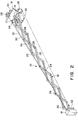
- Fig. 1 depicts the boom assembly 10 in the fully retracted (stowed) position.
- the boom assembly 10 comprises a boom 12 have a fixed end 14 mounted to a support structure 16 .
- the illustrated support structure 16 is an optical bench suitable for mounting to a spacecraft.
- the boom assembly 10 can also be mounted to other types of support structures in various celestial and terrestrial applications.
- a device 18 such as an interferometer is mounted to the distal end 20 of the boom assembly 10 .
- Other types of devices such as telescopes, scientific instruments, cameras, antennas and the like can be mounted to the distal end 20 of the boom 12 as well.
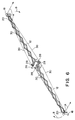
- the illustrated boom 12 is known as a scissors boom.
- the boom 12 comprises a plurality of leg members 22 shown in the fully retracted condition in Fig. 1, and in the fully deployed condition in Fig. 2.
- the leg members 22 are interconnected by pins 24 and opposed ends of the leg members 22 are connected by hinges 26 .
- the hinges 26 are preferably strain energy hinges each including a strain energy spring (not shown) to provide an extension force to urge the boom 12 to deploy outwardly away from the support structure 16 .
- the use of springs in each hinge 26 provides a uniform load distribution to the boom 12 and reduces frictional loads in the hinges 26 .
- a single deployment assist spring or other type of deployment assist means such as a hydraulic actuator (not shown) can be mounted at the fixed end 14 of the boom 12 to provide the extension force to deploy the boom 12 .
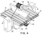
- the boom assembly 10 further comprises cable deployment means to selectively deploy and retract the cables 30 during respective deployment and retraction of the boom 12 .
- the cable deployment means typically comprises a plurality of cable winding devices such as cable drums 28 mounted to the support structure 16 .
- a cable 30 is attached to each cable drum 28 . Operation of the cable drums 28 causes the cables 30 to be unwound and wound to respectively deploy and retract the boom 12 .
- the cable drums 28 are mounted to the support structure 16 at angularly spaced locations. As shown, the three cable drums 28 are typically symmetrically position at an angular spacing of about 120° relative to each other.
- the cables 30 each extend from the cable drums 28 at an angle ⁇ relative to the support structure 16 .
- This angle determines the axial and lateral components of the tension in the cables 30 and the angle can be selectively varied.
- Packaging constraints can limit the angle in spacecraft applications of the boom assembly 10 .
- the cables 30 are attached to the distal end 20 of the boom 12 .
- the cables 30 can be attached directly to the boom 12 or, for example, to a mounting plate 32 of the device 18 as shown.
- the boom assembly 10 further comprises actuation means for actuating the cable drums 28 to selectively vary the length of the cables 30 deployed from the cable drums 28 to vary the deployed length of the boom 12 .
- the cable drums 28 are preferably each separately driven by an actuator including a stepping motor 33 and associated drive electronics (not shown).
- the stepping motors 33 provide precise payout and retraction of the cables 30 for precise positional control of the distal end 20 of the boom 12 .
- the cable drums 28 are preferably precision manufactured such that the cable groove 29 is a continuous spiral having a substantially constant diameter along the groove 29 .
- the cable drums 28 and the stepping motors 33 allow the device 18 to be moved axially in increments typically as small as about 20 microns, providing almost infinite axial adjustment of the device 18 to ensure its precise position.
- the device 18 can be selectively moved and precisely repositioned at other axial deployed position or can be fully retracted.
- the device 18 can be repositioned repeatedly at substantially the same axial position.
- Each cable drum 28 is preferably selectively, independently actuated by a stepping motor 33 to enable lateral positioning of the boom 12 and the device 18 . Lateral adjustment of the boom 12 in increments as small as about 150 microns can typically be achieved with the boom assembly 10 .
- the actuation means of the boom assembly 10 can further comprise one or more position sensing or distance measuring devices such as an optical rangefinder 34 (Fig. 2) or the like, that precisely measures the location of the device 18 .
- a position sensing or distance measuring device such as an optical rangefinder 34 (Fig. 2) or the like, that precisely measures the location of the device 18 .
- Such a device can also be incorporated to control the lateral position of the device 18 .
- the rangefinder 34 determines the position of the device 18 and provides a signal to the actuator to drive the cable drums 28 to wind or unwind the cables 30 based on the sensed position.
- the signal can be inputted to the drive electronics of the stepping motors 33 to adjust the stepping motor 33 counts to provide even greater precision.
- the boom assembly 10 preferably comprises three cables 30 and, accordingly, three cable drums 28 and stepping motors 33 .
- the boom 12 and three cables 30 form a tripod configuration having high structural and dimensional stability. Less than three cables 30 do not provide the needed lateral support to the boom 12 . More than three cables 30 provide the necessary lateral support, but introduce redundant load paths. In addition, redundant cables add undesired weight along with that of the required added cable drums and actuators to the boom assembly 10 .
- the boom 12 produces a tensile pre-load extension force in the cables 30 to stabilize the boom assembly 10 .
- Various types of booms that provide this same function can optionally be used.
- a telescoping tube system (not shown) can be substituted for the illustrated scissors boom 12 in some applications.
- Such a tube system is less preferred than the scissors boom 12 , however, because although the tube system has high stability and stiffness at the fully extended position, it is less stable at intermediate positions. Accordingly, tube systems are well suited for applications of the boom assembly 10 that do not require intermediate positioning of the boom 12 .
- the tensile pre-load force in the cables 30 substantially eliminates deadband in the boom assembly 10 .
- Any axial play in the leg members 22 of the boom 12 is countered by the tensile force in the cables 30 so that the deployed boom 12 length is highly stable. Consequently, the exact location of the device 18 mounted to the boom 12 is always precisely determinable.
- the elimination of deadband in the boom assembly 10 allows the spacecraft control system to effectively control the motion of the spacecraft without having to overcome the effects of deadband in the boom assembly 10 .
- the tensile force in the cables also eliminates hysteresis in the boom 12 . That is, if a hinge joint 26 of the boom 12 unloads after the boom 12 is positioned at some location, the change in load resulting from the release of friction is insufficient to significantly change the length of the cables 30 and, accordingly, the position of the device 18 mounted to the boom 12 .
- the cables 30 act as structural members so long as the tensile pre-load force is applied to the cables 30 by the boom 12 .
- the cables 30 are preferably formed of a material that has a high stiffness and high stiffness/weight ratio, so that the high stiffness is not achieved by significantly increasing the weight of the boom assembly 10 .
- a high stiffness in the cables 30 provides several advantages.
- the cables 30 act as the primary structural members of the boom assembly 10 and, so, a high stiffness provides high structural stability to the boom assembly 10 .
- a high stiffness also ensures high positional stability of the distal end 20 of the boom 12 and the mounted device 18 .
- An excellent material for forming the cables 30 that provides high stiffness and a high stiffness/weigh ratio is graphite.
- the cables preferably have a density of less than about 0.07 lb/in 3 and a coefficient of thermal expansion of an absolute value of less than about 0.01 x 10 -6 in/in-°F.
- the cables 30 provide positional stability to the distal end 20 of the boom 12 and, so, it is important that the cables 30 are dimensionally stable.
- the temperature in space can vary significantly over the course of a spacecraft's orbit.
- Graphite has an extremely low coefficient of thermal expansion.
- the coefficient of thermal expansion of the cables 30 is about -0.01 x 10 -6 in/in-°F. Accordingly, even large temperature changes encountered by the boom assembly 10 produce minimal changes in the length of the cables 30 .
- any thermal expansion (or contraction) of the boom 12 is not imparted to the cables 30 because the resulting forces created in the boom 12 are insufficient in magnitude to overcome the tensile forces in the cables 30 , and so the end of the boom 12 remains substantially fixed.
- This dimensional stability ensures that the position of the device 18 mounted to the boom 12 remains substantially fixed at all deployed positions or the boom 12 .
- the cables 30 can be formed by applying a suitable coating material such as nickel to graphite cables.
- the coating material preferably has a positive coefficient of thermal expansion.
- the resulting coefficient of thermal expansion of coated graphite cables can typically be selectively tailored to an absolute value of much less than about 0.5 x 10 -6 in/in-°F.
- the nickel-plated graphite cables are typically sheathed in a jacket of a material such as "DACRON".
- the graphite cables 30 also provide for a sufficiently high natural structural frequency of the boom assembly 10 to prevent coupling in with spacecraft attitude sensors.
- the structural frequency is the frequency of lateral movement of the boom assembly 10 .
- the structural frequency of the boom assembly 10 is typically greater than about 1 Hz.
- the feedback loop frequency of the attitude sensors used in spacecraft is typically much less than 1 Hz. Accordingly, the graphite cables 30 provide for a sufficient difference between these two frequencies to eliminate the problem of frequency coupling. Consequently, the thrusters and reactions wheels are able to perform their function of controlling the spacecraft attitude and not respond to vibrations in the boom assembly 10 , and precious fuel is not wasted due to unnecessary use of the attitude control devices.
- the boom 12 can also be formed of graphite to provide the same above-described advantages provided by the cables 30 .
- more than one deployable boom assembly 10 in accordance with the invention can be mounted to a support structure 36 . As shown, a pair of deployable booms 10 are mounted along substantially a common longitudinal axis.
- the support structure 36 is mounted to a base 38 .
- the cable drums 28 are arranged side-by-side on supporting brackets 40 connected to the base 38 .
- the base 38 can be attached to a surface such as a satellite outer wall.
- Shear pins 42 provided on the pair of interferometers 18 engage grooves 44 formal at opposite ends of the base 38 in the illustrated stowed position of the boom assemblies 10 .
- a latching mechanism 46 is typically provided to retain the boom assemblies 10 in the stowed position during launch and landing events.
- Fig. 6 shows the booms 12 fully deployed.
- the arrows A indicate the light paths for the interferometers 18 .
- By mounting the interferometers 18 in pairs at the distal ends 20 of the aligned booms 12 it is possible to measure distant planets and solar systems by circularly rotating the booms 12 as represented by arrows B.
- the length of each boom 12 can be precisely varied.
- the pracise positioning capabilities of the boom 12 enables the interferometers 18 to be positioned the same distance from the support structure 36 to provide uniform circular mapping.
- the booms 12 enable the interferometers 18 to be repositioned at substantially any location, for example, if a measurement needs to be precisely repeated.
- Fig. 8 shows the deployed boom assemblies 10 of Fig. 6 as mounted to a base 52 on a satellite 50 .
- a pair of solar panel arrays 54 are also shown mounted to the satellite 50
- pairs of boom assemblies 10 can be mounted parallel to each other on a support surface, or mounted at an angle relative to each other.
- the boom assembly 10 in accordance with the invention has utility for various terrestrial applications that require the precise, repeatable positioning of an object.
- the boom assembly 10 can be used to deploy antennas and scientific instruments to precise positions.
- the boom assembly 10 can be provided in various boom 12 lengths.
- the deployed boom 12 length is typically as much as 25 meters.
- Other shorter and longer booms 12 are possible.
- the pre-loaded, stiff cables 30 in combination with the extension force provided by the scissors booms 12 provide high stability and precise positioning of the boom 12 for a wide range of boom 12 lengths.
Abstract
Description
Claims (22)
- A precision deployable boom assembly for use on a supporting structure, the boom assembly comprising:a) a deployable and retractable boom having a fixed end for fixedly securing to a surface of the supporting structure and a distal end selectively movable relative to the fixed end;b) at least three cables, each cable having a first end connected to the distal end of the boom and a second end;c) cable deployment means secured to the second end of the cables for selectively deploying and retracting the cables during respective deployment and retraction of the boom, the cable deployment means being securable to the supporting structure;d) deployment assist means for urging the boom to deploy and for producing a tensile pre-load force in each of the cables; ande) actuation means for actuating the cable deployment means to selectively vary the length of the cables deployed from the cable deployment means to thereby vary the length of the boom between the fixed end and the distal end;f) wherein the distal end of the boom is (i) positionable at substantially any position between fully deployed and fully retracted positions; (ii) repeatedly positionable at substantially any deployed position of the boom; and (iii) substantially positionally stable at any deployed position.
- The boom assembly of claim 1, wherein the cable deployment means comprises three cable drums and the boom assembly comprises three cables, each cable drum defines a continuous spiral-shaped groove, and the second end of each cable is secured to one of the cable drums.
- The boom assembly of claim 2, wherein the cable drums are substantially symmetrically positionable relative to each other on the supporting structure such that the cables extend at approximately the same angle relative to the surface of the supporting structure between the cable drums and the distal end of the boom to form a tripod configuration.
- The boom assembly of claim 2, wherein the actuation means comprises three stepping motors, each stepping motor is drivingly connected to one of the cable drums.
- The boom assembly of claim 4, wherein the actuation means further comprises at least one position sensor for sensing the position of the distal end of the boom, and the stepping motors are actuated to drive the cable drums based on the sensed position of the distal end of the boom.
- The boom assembly of claim 1, wherein the cables have i) a coefficient of thermal expansion of an absolute value of less than about 0.01 x 10⁻⁶ in/in-°F, and ii) a density of less than about 0.07 lb/in3.
- The boom assembly of claim 1, wherein the cables are comprised of graphite or nickel-plated graphite.
- The boom assembly of claim 1, wherein the boom is a scissors boom including a plurality of legs interconnected by hinges, the deployment assist means comprises a plurality of strain energy springs, each spring is disposed in one of the hinges.
- The boom assembly of claim 1, wherein the boom is comprised of graphite.
- The boom assembly of claim 1, wherein the boom assembly has (i) a structural frequency of greater than about 1 Hz, (ii) substantially no deadband, and (iii) substantially no hysteresis.
- A precision deployable boom assembly for use on a supporting structure, the boom assembly comprising:a) a deployable and retractable scissors boom having a fixed end for fixedly securing to a surface of the supporting structure and a distal end selectively movable relative to the fixed end, the scissors boom including a plurality of legs interconnected by hinges, and a strain energy spring disposed in a plurality of the hinges to urge the scissors boom to deploy;b) three graphite cables, each cable having a first end secured to the distal end of the scissors boom and a second end, the scissors boom producing a tensile pre-load force in each of the graphite cables;c) three cable drums for securing to the supporting structure, each cable being secured at the second end to one of the cable drums, each cable drum unwinding and winding one of the graphite cables during respective deployment and retraction of the scissors boom, and each cable drum defining a continuous spiral-shaped groove; andd) three stepping motors, each stepping motor being drivingly connected to one of the cable drums to selectively vary the length of the graphite cables deployed from the cable drum to thereby vary the deployed length of the scissors boom between the fixed end and distal end;e) wherein the distal end of the scissors boom is (i) positionable at substantially any position between fully deployed and fully retracted positions; (ii) repeatedly positionable at substantially any deployed position; and (iii) substantially positionally stable at any deployed position.
- The boom assembly of claim 11, wherein the cable drums are substantially summetrically positionable relative to each other on the supporting structure such that the graphite cables extend at approximately the same angle relative to the surface of the supporting structure between the fixed end and distal end of the boom to form a tripod configuration.
- The boom assembly of claim 11, further comprising at least one position sensor for sensing the position of the distal end of the scissors boom, the stepping motors are selectively actuable to drive the cable drums based on the sensed position of the distal end so as to deploy or retract the scissors boom.
- The boom assembly of claim 11, wherein the graphite cables are nickel-plated.
- The boom assembly of claim 11, wherein the scissors boom is comprised of graphite.
- The boom assembly of claim 11, wherein the boom assembly has (i) a structural frequency of greater than about 1 Hz; (ii) substantially no deadband; and (iii) substantially no hysteresis.
- In combination:a) a supporting structure having at least one support surface;b) at least one precision deployable boom assembly mounted to the support surface of the supporting structure, each boom assembly comprising:i) a deployable and retractable boom having a fixed end fixedly secured to the support surface and distal end selectively movable relative to the fixed end;ii) at least three cables, each cable having a first end connected to the distal end of the boom, the cables having a coefficient of thermal expansion of an absolute value of less than about 0.01 x 10⁻⁶ in/in-°F, and a density of less than about 0.07 lb/in3;iii) cable deployment means secured to the second end of the cables for selectively deploying and retracting the cables during respective deployment and retraction of the boom, the cable deployment means being securable to the supporting structure;iv) deployment assist means for urging the boom to deploy and for producing a tensile pre-load force in each of the cables; andv) actuation means for actuating the cable deployment means to selectively vary the length of the cables deployed from the cable deployment means to thereby vary the length of the boom between the fixed end and the distal end;vi) wherein the distal end of the boom is (a) positionable at substantially any position between fully deployed and fully retracted positions; (b) repeatedly positionable at substantially any deployed position of the boom; and (c) substantially positionally stable at any deployed position;vii) wherein the boom assembly has (a) a structural frequency of greater than about 1 Hz; (b) substantially no deadband; and (c) substantially no hysteresis.
- The combination of claim 17, comprising a plurality of boom assemblies mounted to the supporting structure.
- A spacecraft assembly, comprising:a) a spacecraft having at least a first support surface;b) at least one precision deployable boom assembly mounted to the first support surface, each boom assembly comprising:i) a deployable and retractable boom having a fixed end fixedly secured to the first support surface and a distal end selectively movable relative to the fixed end;ii) three cables each having a first end secured to the distal end of the boom, the cables having a coefficient of thermal expansion of an absolute value of less than about 0.01 x 10⁻⁶ in/in-°F, and a density of less than about 0.07 lb/in3;iii) cable deployment means secured to the second end of the cables for selectively deploying and retracting the cables during respective deployment and retraction of the boom, the cable deployment means being secured to the first support surface;iv) deployment assist means for urging the boom to deploy and for producing a tensile pre-load force in each of the cables; andv) actuation means for actuating the cable deployment means to selectively vary the length of the cables deployed from the cable deployment means to thereby vary the length of the boom between the fixed end and the distal end;vi) wherein the distal end of the boom is (i) positionable at substantially any position between fully deployed and fully retracted positions; (ii) repeatedly positionable at substantially any deployed position of the boom; and (iii) substantially positionally stable at any deployed position.
- The spacecraft assembly of claim 19, wherein the spacecraft is a satellite.
- The spacecraft assembly of claim 20, comprising two deployable boom assemblies and the spacecraft further comprises a second support surface, the boom assemblies are mounted to the first and second support surfaces such that the booms lie substantially along a common axis, and the distal ends of the booms face in opposite directions.
- The spacecraft assembly of claim 19, wherein the boom assembly has (i) a structural frequency of greater than about 1 Hz; (ii) substantially no deadband; and (iii) substantially no hysteresis.
Applications Claiming Priority (2)
| Application Number | Priority Date | Filing Date | Title |
|---|---|---|---|
| US789146 | 1997-01-28 | ||
| US08/789,146 US5857648A (en) | 1997-01-28 | 1997-01-28 | Precision deployable boom assembly |
Publications (2)
| Publication Number | Publication Date |
|---|---|
| EP0858946A1 true EP0858946A1 (en) | 1998-08-19 |
| EP0858946B1 EP0858946B1 (en) | 2005-09-28 |
Family
ID=25146722
Family Applications (1)
| Application Number | Title | Priority Date | Filing Date |
|---|---|---|---|
| EP98100709A Expired - Lifetime EP0858946B1 (en) | 1997-01-28 | 1998-01-16 | Precision deployable boom assembly |
Country Status (4)
| Country | Link |
|---|---|
| US (1) | US5857648A (en) |
| EP (1) | EP0858946B1 (en) |
| JP (1) | JP3286237B2 (en) |
| DE (1) | DE69831695T2 (en) |
Cited By (12)
| Publication number | Priority date | Publication date | Assignee | Title |
|---|---|---|---|---|
| EP0955237A3 (en) * | 1998-05-05 | 1999-11-24 | Eurocopter Deutschland GmbH | Cable connection for solar panel deployment on satellites |
| DE19855994A1 (en) * | 1998-12-04 | 2000-06-15 | Daimler Chrysler Ag | Deployable solar generator for a spacecraft |
| DE10048846C1 (en) * | 2000-10-02 | 2001-09-13 | Astrium Gmbh | Roll-out solar generator for rolling out solar cell structure has roll-out support structure with first transverse support connecting to storage casing for solar cell structure. |
| EP1184280A2 (en) | 2000-09-02 | 2002-03-06 | Astrium GmbH | Deployable carrier structure made of deformable tube elements |
| FR2933076A1 (en) * | 2008-06-25 | 2010-01-01 | Centre Nat Etd Spatiales | DEPLOYABLE MATTER WITH REPLACED SPONTANEOUS FRACTURE DEPLOYABLE AND RIGID IN DEPLOYED STATE |
| FR2933075A1 (en) * | 2008-06-25 | 2010-01-01 | Centre Nat Etd Spatiales | DEPLOYABLE MATTER WITH REPLACED DEPLOYABLE FRAMEWORK LOCKING BY CONSTRUCTION IN THE DEPLOYED STATE |
| CN104276291A (en) * | 2014-10-23 | 2015-01-14 | 东南大学 | Rigid-flexible combined minor planet surface work auxiliary mechanism |
| WO2017123349A3 (en) * | 2015-12-08 | 2017-10-12 | Space Systems/Loral, Llc | Spacecraft with rigid antenna reflector deployed via linear extension boom |
| CN108466705A (en) * | 2018-03-28 | 2018-08-31 | 哈尔滨工业大学 | A kind of Steel Belt Transmission multilevel sleeve type Zhan Shou mechanisms |
| EP3666665A1 (en) * | 2018-12-13 | 2020-06-17 | Thales | Deployable device with control of deployed length of a deployable structure |
| WO2021170310A1 (en) * | 2020-02-27 | 2021-09-02 | Jürgen Weingärtner | Crane device |
| US11440182B2 (en) | 2017-04-25 | 2022-09-13 | Sony Corporation | Expansion device and movable body |
Families Citing this family (65)
| Publication number | Priority date | Publication date | Assignee | Title |
|---|---|---|---|---|
| US6343442B1 (en) * | 1999-08-13 | 2002-02-05 | Trw-Astro Aerospace Corporation | Flattenable foldable boom hinge |
| US8074324B2 (en) * | 1999-11-09 | 2011-12-13 | Foster-Miller, Inc. | Flexible, deployment rate damped hinge |
| US6353421B1 (en) | 2000-09-14 | 2002-03-05 | Ball Aerospace And Technologies Corp. | Deployment of an ellectronically scanned reflector |
| GB0122357D0 (en) * | 2001-09-15 | 2001-11-07 | Secr Defence | Sub-surface radar imaging |
| US6910304B2 (en) * | 2002-04-02 | 2005-06-28 | Foster-Miller, Inc. | Stiffener reinforced foldable member |
| US6637702B1 (en) * | 2002-04-24 | 2003-10-28 | Lockheed Martin Corporation | Nested beam deployable solar array |
| DE10259638B4 (en) * | 2002-12-18 | 2004-12-09 | Intersecure Logic Limited | Service vehicle to perform actions on a target spacecraft, maintenance system, and method of using a service vehicle |
| US7694486B2 (en) * | 2003-12-12 | 2010-04-13 | Alliant Techsystems Inc. | Deployable truss having second order augmentation |
| DE602004018360D1 (en) * | 2004-12-28 | 2009-01-22 | Alcatel Lucent | Connecting device for space equipment elements with flexible deployable blades |
| US8042305B2 (en) * | 2005-03-15 | 2011-10-25 | Alliant Techsystems Inc. | Deployable structural assemblies, systems for deploying such structural assemblies |
| US7694465B2 (en) | 2005-04-08 | 2010-04-13 | Alliant Techsystems Inc. | Deployable structural assemblies, systems for deploying such structural assemblies and related methods |
| US8627738B2 (en) * | 2005-06-29 | 2014-01-14 | Thomas Scott Breidenbach | Linear-curvilinear actuating apparatus with rotating joints |
| US7845708B2 (en) * | 2007-06-06 | 2010-12-07 | Adaptive Aerodynamic, Llc | Aerodynamic drag reducing apparatus |
| US7380868B2 (en) * | 2005-06-29 | 2008-06-03 | Thomas Scott Breidenbach | Aerodynamic drag reducing apparatus |
| US7963084B2 (en) | 2005-08-29 | 2011-06-21 | Donald Merrifield | Deployable triangular truss beam with orthogonally-hinged folding diagonals |
| US7416168B1 (en) * | 2005-09-26 | 2008-08-26 | Bob's Space Racers, Inc. | Prize lift telescoping assembly |
| US7618086B2 (en) | 2005-12-01 | 2009-11-17 | Thomas Scott Breidenbach | Aerodynamic drag reducing apparatus |
| US8376282B2 (en) | 2006-03-31 | 2013-02-19 | Composite Technology Development, Inc. | Collapsible structures |
| US8066227B2 (en) * | 2006-03-31 | 2011-11-29 | Composite Technology Development, Inc. | Deployable structures having collapsible structural members |
| US8387921B2 (en) * | 2006-03-31 | 2013-03-05 | Composite Technology Development, Inc. | Self deploying solar array |
| US8109472B1 (en) | 2006-03-31 | 2012-02-07 | Composite Technology Development, Inc. | Collapsible structures with adjustable forms |
| US7806370B2 (en) * | 2006-03-31 | 2010-10-05 | Composite Technology Development, Inc. | Large-scale deployable solar array |
| US7762500B1 (en) * | 2006-11-06 | 2010-07-27 | Sanjay Dhall | Telescopic wing with articulated structural spar |
| US8360509B2 (en) | 2007-05-17 | 2013-01-29 | Advanced Transit Dynamics, Inc. | Rear-mounted aerodynamic structure for truck cargo bodies |
| US8100461B2 (en) | 2007-05-17 | 2012-01-24 | Advanced Transit Dynamics, Inc. | Rear-mounted aerodynamic structure for truck cargo bodies |
| US20110001016A1 (en) * | 2007-12-18 | 2011-01-06 | Robert Stewart Skillen | Telescoping and sweeping wing that is reconfigurable during flight |
| US20090184207A1 (en) * | 2008-01-22 | 2009-07-23 | Warren Peter A | Synchronously self deploying boom |
| US7857376B2 (en) * | 2008-02-21 | 2010-12-28 | Adaptive Aerodynamic, Llc | Aerodynamic drag reducing apparatus |
| WO2010054274A2 (en) * | 2008-11-06 | 2010-05-14 | Robert Stancel | Tensioned mounting of solar panels |
| US9281569B2 (en) | 2009-01-29 | 2016-03-08 | Composite Technology Development, Inc. | Deployable reflector |
| WO2011006506A1 (en) | 2009-07-15 | 2011-01-20 | Aalborg Universitet | Foldable frame supporting electromagnetic radiation collectors |
| US20110042530A1 (en) * | 2009-08-19 | 2011-02-24 | Mark Phillips | Flexipod with flexible bendable legs with a gripping surface |
| US8905357B1 (en) * | 2009-10-02 | 2014-12-09 | MMA Design, LLC | Thin membrane structure |
| US8683755B1 (en) * | 2010-01-21 | 2014-04-01 | Deployable Space Systems, Inc. | Directionally controlled elastically deployable roll-out solar array |
| CN101823564B (en) * | 2010-03-31 | 2012-11-14 | 北京航空航天大学 | Super-elasticity coiled space-developable mechanism using precision U hinge |
| US8814099B1 (en) * | 2010-08-31 | 2014-08-26 | MMA Design, LLC | Deployable morphing modular solar array |
| US8616502B1 (en) * | 2010-09-03 | 2013-12-31 | The Boeing Company | Deployable solar panel assembly for spacecraft |
| US9550584B1 (en) * | 2010-09-30 | 2017-01-24 | MMA Design, LLC | Deployable thin membrane apparatus |
| US10773833B1 (en) | 2011-08-30 | 2020-09-15 | MMA Design, LLC | Panel for use in a deployable and cantilevered solar array structure |
| US20130076064A1 (en) | 2011-09-20 | 2013-03-28 | Advanced Transit Dynamics, Inc. | Rear-mounted retractable aerodynamic structure for cargo bodies |
| US9440689B1 (en) | 2011-09-20 | 2016-09-13 | Stemco Lp | Aerodynamic structures secured to the underbody of cargo bodies |
| EP2771231A4 (en) | 2011-10-27 | 2016-01-06 | Advanced Transit Dynamics Inc | Rear-mounted aerodynamic structures for cargo bodies |
| WO2013116632A1 (en) * | 2012-02-02 | 2013-08-08 | United States Of America, As Represented By The Administrator Of The National Aeronautics And Space Administration | Tension stiffened and tendon actuated manipulator and a hinge for use therein |
| MX2015000462A (en) | 2012-07-11 | 2015-12-07 | Advanced Transit Dynamics Inc | Retractable aerodynamic structures for cargo bodies and methods of controlling positioning of the same. |
| FR2997385B1 (en) * | 2012-10-26 | 2014-11-28 | Thales Sa | MOTORIZATION SYSTEM FOR ARTICULATION WITH FLEXIBLE BEARING RUNWAYS |
| US9073647B2 (en) | 2013-04-25 | 2015-07-07 | Biosphere Aerospace Llc | Space shuttle orbiter and return system |
| CN103693217A (en) * | 2013-12-06 | 2014-04-02 | 上海卫星工程研究所 | Retractable spatial stretching arm for satellite |
| USD751498S1 (en) | 2014-10-08 | 2016-03-15 | Composite Technology Development, Inc. | Trifold solar panel |
| USD754598S1 (en) | 2014-10-08 | 2016-04-26 | Composite Technology Development, Inc. | Trifold solar panel |
| USD755118S1 (en) | 2014-10-08 | 2016-05-03 | Composite Technology Development, Inc. | Trifold solar panel |
| USD755119S1 (en) | 2014-10-08 | 2016-05-03 | Composite Technology Development, Inc. | Trifold solar panel |
| CN104875908B (en) * | 2015-02-11 | 2017-01-25 | 北京航空航天大学 | Cable-driven passive tensioning device of deployable mechanism |
| US10569415B2 (en) | 2016-08-31 | 2020-02-25 | United States Of America As Represented By The Administrator Of Nasa | Tension stiffened and tendon actuated manipulator |
| WO2018093761A1 (en) * | 2016-11-16 | 2018-05-24 | University Of Florida Research Foundation, Inc. | Drag-based propellant-less small satellite attitude orbit and de-orbit control system |
| CN106584438B (en) * | 2017-01-24 | 2022-11-15 | 重庆大学 | Spacecraft prestress conical thin-wall three-rod parallel space unfolding mechanism |
| US10546967B2 (en) * | 2017-04-21 | 2020-01-28 | Lockheed Martin Corporation | Multi-mission modular array |
| FR3071822B1 (en) * | 2017-10-04 | 2020-11-27 | Arianegroup Sas | DEPLOYABLE SATELLITE MAT |
| EP3758897A4 (en) * | 2018-02-28 | 2021-12-29 | Oceaneering International, Inc. | Subsea inspection vehicle |
| US10811759B2 (en) | 2018-11-13 | 2020-10-20 | Eagle Technology, Llc | Mesh antenna reflector with deployable perimeter |
| US11139549B2 (en) | 2019-01-16 | 2021-10-05 | Eagle Technology, Llc | Compact storable extendible member reflector |
| US10797400B1 (en) | 2019-03-14 | 2020-10-06 | Eagle Technology, Llc | High compaction ratio reflector antenna with offset optics |
| US11319093B2 (en) * | 2019-05-06 | 2022-05-03 | Eagle Technology, Llc | Deployment mechanism for reflector antenna system |
| US11223111B2 (en) * | 2020-06-11 | 2022-01-11 | Eagle Technology, Llc | Systems and methods for providing antennas with mechanically coupled offset positions |
| US11411318B2 (en) * | 2020-12-08 | 2022-08-09 | Eagle Technology, Llc | Satellite antenna having pantographic trusses and associated methods |
| CN115009541B (en) * | 2021-04-12 | 2023-12-26 | 北京邮电大学 | Hinge formula expansion mechanism that turns over of rope linkage |
Citations (6)
| Publication number | Priority date | Publication date | Assignee | Title |
|---|---|---|---|---|
| US3496687A (en) * | 1967-03-22 | 1970-02-24 | North American Rockwell | Extensible structure |
| US4237662A (en) * | 1978-04-04 | 1980-12-09 | The United States Of America As Represented By The Administrator Of The National Aeronautics & Space Administration | Structural members, method and apparatus |
| US4337560A (en) * | 1978-08-03 | 1982-07-06 | General Dynamics, Convair Division | Method for assembling large space structures |
| FR2500946A1 (en) * | 1981-02-16 | 1982-09-03 | Dahmani B | Aerial support allowing movement of TV or cine camera - has two vertical masts supporting horizontal scissor jack mounted on pulleys and supporting camera |
| EP0408826A2 (en) * | 1989-07-19 | 1991-01-23 | Japan Aircraft Mfg. Co., Ltd | Extendable mast |
| EP0457683A1 (en) * | 1990-05-18 | 1991-11-21 | AEROSPATIALE Société Nationale Industrielle | Reel with captive cable and its use in a deployment regulator of an appendix of a spacecraft |
Family Cites Families (24)
| Publication number | Priority date | Publication date | Assignee | Title |
|---|---|---|---|---|
| US370833A (en) * | 1887-10-04 | Fire-escape | ||
| US418827A (en) * | 1890-01-07 | Half to louis boisseau | ||
| US775158A (en) * | 1904-05-23 | 1904-11-15 | John Wenig | Fire-escape. |
| US797077A (en) * | 1904-06-03 | 1905-08-15 | Robert Fleming | Aerial ladder, elevator, or lift. |
| US818304A (en) * | 1905-06-02 | 1906-04-17 | Robert Fleming | Aerial ladder. |
| US836868A (en) * | 1906-03-29 | 1906-11-27 | John C Dangerfield | Fire-escape. |
| US1003967A (en) * | 1909-05-29 | 1911-09-19 | Erasmo Magliocca | Combined water-tower and fire-escape. |
| US1025972A (en) * | 1909-10-25 | 1912-05-14 | Cristoph J Geisel | Portable fire-escape. |
| US967116A (en) * | 1910-02-15 | 1910-08-09 | Ignace Coulombe | Extension fire-ladder. |
| US1078759A (en) * | 1912-09-23 | 1913-11-18 | Arend Wichertjes | Fire-escape. |
| US1113158A (en) * | 1913-09-08 | 1914-10-06 | Paul Winfrey | Fire-escape. |
| US1708113A (en) * | 1927-06-29 | 1929-04-09 | Alvah K Allen | Collapsible tower |
| US2363784A (en) * | 1943-06-28 | 1944-11-28 | Gerich Valentine | Collapsible crane or platform tower |
| US3588050A (en) * | 1969-05-08 | 1971-06-28 | Us Army | Automatic guy wire tensioning device |
| DE3222475A1 (en) * | 1981-06-19 | 1983-01-27 | British Aerospace Public Ltd. Co., London | EXTENDABLE MASTER STRUCTURE |
| US4524552A (en) * | 1981-10-09 | 1985-06-25 | General Dynamics Corporation/Convair Div. | Mechanism for deploying a deployable truss beam |
| JPS5922898A (en) * | 1982-07-24 | 1984-02-06 | 株式会社 彦間製作所 | Height lifting gear |
| DE3316789A1 (en) * | 1983-05-07 | 1984-11-08 | Licentia Patent-Verwaltungs-Gmbh, 6000 Frankfurt | METHOD AND DEVICE FOR FOLDING IN OR FOLDING OUT A FOLDABLE SOLAR CELL GENERATOR SHEET |
| IT1162948B (en) * | 1983-09-30 | 1987-04-01 | Aeritalia Spa | EXTENSIBLE ARM PARTICULARLY FOR VEHICLES OR SPACE MODULES |
| US4725025A (en) * | 1986-03-21 | 1988-02-16 | Rca Corporation | Deployment system |
| US4850161A (en) * | 1987-11-30 | 1989-07-25 | Mcginnis Henry J | Extensible mast support system |
| US4900891A (en) * | 1988-06-20 | 1990-02-13 | Roger Vega | Laser ice removal system |
| US4969301A (en) * | 1989-06-14 | 1990-11-13 | Aec-Able Engineering Company, Inc. | Relatchable launch restraint mechanism for deployable booms |
| US5228644A (en) * | 1991-05-28 | 1993-07-20 | The United States Of America As Represented By The United States National Aeronautics And Space Administration | Solar powered system for a space vehicle |
-
1997
- 1997-01-28 US US08/789,146 patent/US5857648A/en not_active Expired - Fee Related
-
1998
- 1998-01-16 EP EP98100709A patent/EP0858946B1/en not_active Expired - Lifetime
- 1998-01-16 DE DE69831695T patent/DE69831695T2/en not_active Expired - Fee Related
- 1998-01-28 JP JP01525598A patent/JP3286237B2/en not_active Expired - Fee Related
Patent Citations (6)
| Publication number | Priority date | Publication date | Assignee | Title |
|---|---|---|---|---|
| US3496687A (en) * | 1967-03-22 | 1970-02-24 | North American Rockwell | Extensible structure |
| US4237662A (en) * | 1978-04-04 | 1980-12-09 | The United States Of America As Represented By The Administrator Of The National Aeronautics & Space Administration | Structural members, method and apparatus |
| US4337560A (en) * | 1978-08-03 | 1982-07-06 | General Dynamics, Convair Division | Method for assembling large space structures |
| FR2500946A1 (en) * | 1981-02-16 | 1982-09-03 | Dahmani B | Aerial support allowing movement of TV or cine camera - has two vertical masts supporting horizontal scissor jack mounted on pulleys and supporting camera |
| EP0408826A2 (en) * | 1989-07-19 | 1991-01-23 | Japan Aircraft Mfg. Co., Ltd | Extendable mast |
| EP0457683A1 (en) * | 1990-05-18 | 1991-11-21 | AEROSPATIALE Société Nationale Industrielle | Reel with captive cable and its use in a deployment regulator of an appendix of a spacecraft |
Cited By (24)
| Publication number | Priority date | Publication date | Assignee | Title |
|---|---|---|---|---|
| EP0955237A3 (en) * | 1998-05-05 | 1999-11-24 | Eurocopter Deutschland GmbH | Cable connection for solar panel deployment on satellites |
| DE19855994A1 (en) * | 1998-12-04 | 2000-06-15 | Daimler Chrysler Ag | Deployable solar generator for a spacecraft |
| EP1184280A2 (en) | 2000-09-02 | 2002-03-06 | Astrium GmbH | Deployable carrier structure made of deformable tube elements |
| DE10043249A1 (en) * | 2000-09-02 | 2002-03-28 | Astrium Gmbh | Extendable support structure made of deformable tubular elements |
| DE10043249C2 (en) * | 2000-09-02 | 2002-11-07 | Astrium Gmbh | Extendable support structure made of deformable tubular elements |
| EP1184280A3 (en) * | 2000-09-02 | 2003-10-29 | Astrium GmbH | Deployable carrier structure made of deformable tube elements |
| DE10048846C1 (en) * | 2000-10-02 | 2001-09-13 | Astrium Gmbh | Roll-out solar generator for rolling out solar cell structure has roll-out support structure with first transverse support connecting to storage casing for solar cell structure. |
| FR2815934A1 (en) | 2000-10-02 | 2002-05-03 | Astrium Gmbh | DEPLOYABLE SOLAR GENERATOR WITH DEPLOYABLE SUPPORT STRUCTURE |
| US6555740B2 (en) | 2000-10-02 | 2003-04-29 | Astrium Gmbh | Extendible solar generator with an extendible supporting array structure |
| WO2010004169A2 (en) * | 2008-06-25 | 2010-01-14 | Centre National D'etudes Spatiales (C.N.E.S.) | Extendable mast having an extendable folded structure that can be locked when assembled in the extended state |
| FR2933075A1 (en) * | 2008-06-25 | 2010-01-01 | Centre Nat Etd Spatiales | DEPLOYABLE MATTER WITH REPLACED DEPLOYABLE FRAMEWORK LOCKING BY CONSTRUCTION IN THE DEPLOYED STATE |
| WO2010004168A2 (en) * | 2008-06-25 | 2010-01-14 | Centre National D'etudes Spatiales (C.N.E.S.) | Extendable mast having a self-extending folded structure that is rigid in the extended state |
| FR2933076A1 (en) * | 2008-06-25 | 2010-01-01 | Centre Nat Etd Spatiales | DEPLOYABLE MATTER WITH REPLACED SPONTANEOUS FRACTURE DEPLOYABLE AND RIGID IN DEPLOYED STATE |
| WO2010004168A3 (en) * | 2008-06-25 | 2010-03-04 | Centre National D'etudes Spatiales (C.N.E.S.) | Extendable mast having a self-extending folded structure that is rigid in the extended state |
| WO2010004169A3 (en) * | 2008-06-25 | 2010-03-04 | Centre National D'etudes Spatiales (C.N.E.S.) | Extendable mast having an extendable folded structure that can be locked when assembled in the extended state |
| CN104276291A (en) * | 2014-10-23 | 2015-01-14 | 东南大学 | Rigid-flexible combined minor planet surface work auxiliary mechanism |
| WO2017123349A3 (en) * | 2015-12-08 | 2017-10-12 | Space Systems/Loral, Llc | Spacecraft with rigid antenna reflector deployed via linear extension boom |
| US10259599B2 (en) | 2015-12-08 | 2019-04-16 | Space Systems/Loral, Llc | Spacecraft with rigid antenna reflector deployed via linear extension boom |
| US11440182B2 (en) | 2017-04-25 | 2022-09-13 | Sony Corporation | Expansion device and movable body |
| CN108466705A (en) * | 2018-03-28 | 2018-08-31 | 哈尔滨工业大学 | A kind of Steel Belt Transmission multilevel sleeve type Zhan Shou mechanisms |
| EP3666665A1 (en) * | 2018-12-13 | 2020-06-17 | Thales | Deployable device with control of deployed length of a deployable structure |
| FR3089958A1 (en) * | 2018-12-13 | 2020-06-19 | Thales | Deployable device with deployed length control of a deployable structure |
| US11408719B2 (en) | 2018-12-13 | 2022-08-09 | Thales | Deployable device with control of deployed length of a deployable structure |
| WO2021170310A1 (en) * | 2020-02-27 | 2021-09-02 | Jürgen Weingärtner | Crane device |
Also Published As
| Publication number | Publication date |
|---|---|
| DE69831695D1 (en) | 2005-11-03 |
| DE69831695T2 (en) | 2006-07-06 |
| EP0858946B1 (en) | 2005-09-28 |
| JP3286237B2 (en) | 2002-05-27 |
| US5857648A (en) | 1999-01-12 |
| JPH10338200A (en) | 1998-12-22 |
Similar Documents
| Publication | Publication Date | Title |
|---|---|---|
| US5857648A (en) | Precision deployable boom assembly | |
| US8186121B2 (en) | Support device for elements on a piece of space equipment with flexible deploying arms | |
| US6402329B1 (en) | Assembly for mounting and correcting the position of an element, such as a mirror, of a space telescope | |
| JP2959696B2 (en) | Satellite torque balancing method and apparatus | |
| EP0892460B1 (en) | Edge-supported umbrella reflector with low stowage profile | |
| US6920722B2 (en) | Elongated truss boom structures for space applications | |
| JPH02882B2 (en) | ||
| EP3598576B1 (en) | Reflecting systems, such as reflector antenna systems, with tension-stabilized reflector positional apparatus | |
| US6945499B1 (en) | Satellite stand-off tether system | |
| Honeth et al. | Wire Driven Mechanisms for Deployable Components for Optical Payloads | |
| Yalagach et al. | Deployable barrel for a cubesat's optical payload | |
| Sullivan et al. | Boom deployment mechanism for cubesats | |
| US10473094B2 (en) | Thermal morphing anisogrid structure | |
| US20240092509A1 (en) | Under-Constrained Deployable Systems and Components Therefor | |
| Yao et al. | Dynamic analysis on the drag sail device of micro-satellite during the deploying process | |
| Angulo et al. | The Radio Astronomy Explorer 1500-ft-long antenna array | |
| US20230049753A1 (en) | Retractable z-fold flexible blanket solar array | |
| Mettler et al. | Precision segmented reflector figure control system architecture | |
| Greschik | Roll Stabilization for Wrapped Array Prototype | |
| Smola et al. | The Magsat magnetometer boom | |
| Shen et al. | Design and dynamical analysis of a SAR membrane antenna deployable structure | |
| JPS5937881B2 (en) | Gravity tilt stabilized deployable antenna | |
| JPS6118599A (en) | Stiffness holder for space missile expanding structure | |
| JPH08107305A (en) | Antenna reflecting mirror | |
| JPS62255299A (en) | Tension device for space missile |
Legal Events
| Date | Code | Title | Description |
|---|---|---|---|
| PUAI | Public reference made under article 153(3) epc to a published international application that has entered the european phase |
Free format text: ORIGINAL CODE: 0009012 |
|
| AK | Designated contracting states |
Kind code of ref document: A1 Designated state(s): DE FR GB IT |
|
| AX | Request for extension of the european patent |
Free format text: AL;LT;LV;MK;RO;SI |
|
| K1C1 | Correction of patent application (title page) published |
Effective date: 19980819 |
|
| RIN1 | Information on inventor provided before grant (corrected) |
Inventor name: PARKER, A. DALE Inventor name: GILMAN, LARRY N. Inventor name: DAILEY, DEAN R. |
|
| 17P | Request for examination filed |
Effective date: 19980922 |
|
| AKX | Designation fees paid |
Free format text: DE FR GB IT |
|
| RBV | Designated contracting states (corrected) |
Designated state(s): DE FR GB IT |
|
| 17Q | First examination report despatched |
Effective date: 20020826 |
|
| RAP1 | Party data changed (applicant data changed or rights of an application transferred) |
Owner name: NORTHROP GRUMMAN CORPORATION |
|
| RAP1 | Party data changed (applicant data changed or rights of an application transferred) |
Owner name: NORTHROP GRUMMAN CORPORATION |
|
| GRAP | Despatch of communication of intention to grant a patent |
Free format text: ORIGINAL CODE: EPIDOSNIGR1 |
|
| GRAS | Grant fee paid |
Free format text: ORIGINAL CODE: EPIDOSNIGR3 |
|
| GRAA | (expected) grant |
Free format text: ORIGINAL CODE: 0009210 |
|
| AK | Designated contracting states |
Kind code of ref document: B1 Designated state(s): DE FR GB IT |
|
| REG | Reference to a national code |
Ref country code: GB Ref legal event code: FG4D |
|
| REF | Corresponds to: |
Ref document number: 69831695 Country of ref document: DE Date of ref document: 20051103 Kind code of ref document: P |
|
| PGFP | Annual fee paid to national office [announced via postgrant information from national office to epo] |
Ref country code: FR Payment date: 20060117 Year of fee payment: 9 |
|
| PGFP | Annual fee paid to national office [announced via postgrant information from national office to epo] |
Ref country code: DE Payment date: 20060228 Year of fee payment: 9 |
|
| ET | Fr: translation filed | ||
| PLBE | No opposition filed within time limit |
Free format text: ORIGINAL CODE: 0009261 |
|
| STAA | Information on the status of an ep patent application or granted ep patent |
Free format text: STATUS: NO OPPOSITION FILED WITHIN TIME LIMIT |
|
| 26N | No opposition filed |
Effective date: 20060629 |
|
| PG25 | Lapsed in a contracting state [announced via postgrant information from national office to epo] |
Ref country code: DE Free format text: LAPSE BECAUSE OF NON-PAYMENT OF DUE FEES Effective date: 20070801 |
|
| GBPC | Gb: european patent ceased through non-payment of renewal fee |
Effective date: 20070116 |
|
| REG | Reference to a national code |
Ref country code: FR Ref legal event code: ST Effective date: 20070930 |
|
| PG25 | Lapsed in a contracting state [announced via postgrant information from national office to epo] |
Ref country code: GB Free format text: LAPSE BECAUSE OF NON-PAYMENT OF DUE FEES Effective date: 20070116 |
|
| PG25 | Lapsed in a contracting state [announced via postgrant information from national office to epo] |
Ref country code: FR Free format text: LAPSE BECAUSE OF NON-PAYMENT OF DUE FEES Effective date: 20070131 |
|
| PGFP | Annual fee paid to national office [announced via postgrant information from national office to epo] |
Ref country code: IT Payment date: 20080129 Year of fee payment: 11 |
|
| PGFP | Annual fee paid to national office [announced via postgrant information from national office to epo] |
Ref country code: GB Payment date: 20060113 Year of fee payment: 9 |
|
| PG25 | Lapsed in a contracting state [announced via postgrant information from national office to epo] |
Ref country code: IT Free format text: LAPSE BECAUSE OF NON-PAYMENT OF DUE FEES Effective date: 20090116 |