EP0858938B1 - Einrichtung zum Verstellen sowie Verriegeln in Endlagen von zueinander beweglichen Elementen - Google Patents
Einrichtung zum Verstellen sowie Verriegeln in Endlagen von zueinander beweglichen Elementen Download PDFInfo
- Publication number
- EP0858938B1 EP0858938B1 EP98102337A EP98102337A EP0858938B1 EP 0858938 B1 EP0858938 B1 EP 0858938B1 EP 98102337 A EP98102337 A EP 98102337A EP 98102337 A EP98102337 A EP 98102337A EP 0858938 B1 EP0858938 B1 EP 0858938B1
- Authority
- EP
- European Patent Office
- Prior art keywords
- cylinder
- piston rod
- piston
- switching
- switching cylinder
- Prior art date
- Legal status (The legal status is an assumption and is not a legal conclusion. Google has not performed a legal analysis and makes no representation as to the accuracy of the status listed.)
- Expired - Lifetime
Links
- 239000012530 fluid Substances 0.000 claims abstract description 40
- 238000006073 displacement reaction Methods 0.000 claims description 4
- 238000012544 monitoring process Methods 0.000 claims 1
- 230000000284 resting effect Effects 0.000 claims 1
- 238000007789 sealing Methods 0.000 claims 1
- 210000002105 tongue Anatomy 0.000 description 7
- 238000005192 partition Methods 0.000 description 6
- 230000006835 compression Effects 0.000 description 3
- 238000007906 compression Methods 0.000 description 3
- 230000002093 peripheral effect Effects 0.000 description 2
- 230000000712 assembly Effects 0.000 description 1
- 238000000429 assembly Methods 0.000 description 1
- 230000004323 axial length Effects 0.000 description 1
- 230000005540 biological transmission Effects 0.000 description 1
- 230000018109 developmental process Effects 0.000 description 1
- 230000009969 flowable effect Effects 0.000 description 1
- 239000010720 hydraulic oil Substances 0.000 description 1
- 230000003993 interaction Effects 0.000 description 1
- 238000012423 maintenance Methods 0.000 description 1
Images




Classifications
-
- B—PERFORMING OPERATIONS; TRANSPORTING
- B61—RAILWAYS
- B61L—GUIDING RAILWAY TRAFFIC; ENSURING THE SAFETY OF RAILWAY TRAFFIC
- B61L5/00—Local operating mechanisms for points or track-mounted scotch-blocks; Visible or audible signals; Local operating mechanisms for visible or audible signals
- B61L5/04—Fluid-pressure devices for operating points or scotch-blocks
-
- B—PERFORMING OPERATIONS; TRANSPORTING
- B61—RAILWAYS
- B61L—GUIDING RAILWAY TRAFFIC; ENSURING THE SAFETY OF RAILWAY TRAFFIC
- B61L5/00—Local operating mechanisms for points or track-mounted scotch-blocks; Visible or audible signals; Local operating mechanisms for visible or audible signals
- B61L5/10—Locking mechanisms for points; Means for indicating the setting of points
Definitions
- the invention relates to a device for adjusting and locking in end positions of mutually movable elements, in particular movable track sections such as Turnout and frog tip parts, including one to which a working fluid can be applied Piston-cylinder arrangement with double-acting cylinder and stationary, one of the working fluid actable longitudinal bore having a piston rod, along the the cylinder is displaceable, the end positions corresponding to the end positions is lockable and of which a connecting element leading to the adjustment of the element emanates.
- actuators that can be actuated via spindle drives or hydraulic cylinders known from which pushrods start.
- the push rods act on switches Example with clasp tip closures to lock or switch the switch tongues Unlock.
- Known actuators which can be actuated via spindle drives are, for example, the DE 31 06 708 C1, US 4,637,579 or WO 95/08672.
- EP 0 684 174 A1 describes a device for locking movable switch parts known.
- parts in the form of a tube and are movable relative to one another a bolt guided in the tube is provided, the tube over part of it Axial length in the axial direction slots forming spring tongues has, which can engage with their free ends in a stationary outer tube to enable a lock.
- the bolt in turn is with a switch tongue to the tongue Adjust connected. About the bolt itself, the pipe is taken, which in the desired end positions are locked.
- Hydraulic turnout drives are known from DE 25 57 574 B2 and DE 27 44 969 B2 known, in which cylinders are displaceable along a fixed piston rod to switch switch tongues via a transmission linkage.
- One of the control and locking parts independent release of the holding force of the point machine can be achieved when opening the switch.
- the present invention is based on the problem of a device at the beginning mentioned type in such a way that a piston-cylinder arrangement enables safe adjustment and locking and thus fixing of the movable elements is, at the same time a low wear of the elements used and thus Maintenance should be reduced. Furthermore, it should be ensured that the leverage occurring when adjusting are kept as low as possible. Also supposed to be guaranteed that when the element is locked, regardless of the fluid exposure an uncontrolled adjustment is not possible in the piston-cylinder arrangement.
- the problem is essentially solved in that within the Piston rod at least one shift cylinder is arranged axially displaceably, via a first spring element displaceable against the application of force generated by the working fluid is, and that the piston rod starting from the longitudinal bore of at least one radially displaceable locking element is penetrated, which is in an end position located cylinder extends in areas in a receiving chamber of this and in this is held by contact with the shift cylinder.
- the locking of the double-acting cylinder and thus that Set the movable element such as switch tongue or frog tip in their End positions due to the fact that the shift cylinder, which is displaceable within the piston rod, ad locking element engaging in a cavity of the cylinder acts in such a way that it cannot be moved out without adjusting the shift cylinder. So is ensures that the cylinder is in an immovable position with respect to the piston rod occupies.
- the teaching according to the invention also offers the possibility of several adjustment devices designed according to the invention one behind the other and to be arranged in a working fluid circuit, with functional reliability of the circuit is also guaranteed if the cylinder is not in one of the facilities End position can be moved by jamming, for example.
- an auxiliary piston with an axial opening within the shift cylinder is displaceable, one end area of which is connected to the longitudinal bore of the piston rod and the other end area can be closed via a check valve. It also works on the auxiliary piston a spring element such as a disc spring assembly to seal the auxiliary piston opposite the shift cylinder.
- the force caused by the disc spring assembly can then be overcome when the fluid pressure is a predetermined and determined by the Spring force of the disc spring assembly exceeds the specified value.
- the Auxiliary piston moved to the shift cylinder so that working fluid over the auxiliary piston and the shift cylinder to another device, d. H. the interior of another Piston rod can flow along which another cylinder is slidable.
- a within the piston rod wall Connection runs from an interior surrounded by a switching cylinder to another switching cylinder limited by the longitudinal bore predetermined outer space with cylinder locked in an end position and with the same or approximately the same working fluid supply of the first and second shift cylinders.
- each shift cylinder can have a preferably axially extending in the longitudinal bore Switch rod to be connected to monitor the respective position.
- the locking element itself has an axial extent that is smaller than that of Admission chamber is. This ensures that when fluid is applied and from the Displacement of the locking element remote switching cylinder of the cylinder along the Piston rod can be moved radially after the locking element itself moved and removed from the receiving chamber.
- the sliding end walls preferably have a frustoconical geometry.
- the auxiliary piston which functions as a pressure relief valve, is mentioned supported against the shift cylinder, preferably via a plate spring assembly, on the in turn, the spring element is supported, by means of which the shift cylinder counteracts that of the Working fluid-induced force application is displaceable.
- This spring element is furthermore on an intermediate wall of the longitudinal bore of the Piston rod supported.
- the check valve closing the opening or bore of the auxiliary piston comprises a third spring element, the spring force of which is smaller than that of the spring element, which acts on the shift cylinder.
- the spring force of this spring element is again smaller than that of the spring element acting on the auxiliary piston, such as a disk spring assembly.
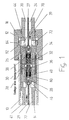
- the facility includes a double acting Cylinder 10 with cylinder heads 12 and 13.
- the cylinder 10 is along a stationary Piston rod 14 slidable, which passes through the cylinder heads 12 and 13. So that Cylinder 10 is displaceable along the piston rod 14, are used as receiving chambers designated working spaces 16, 18 in the cylinder heads 12 and 13 with working fluid such as Hydraulic oil can be acted upon via sections 20, 22 of a longitudinal bore 24 of the piston rod 14 is flowable.
- the sections 20, 22 are over a radially extending partition 30 divided with central bore 32. Sections 20, 22 are axially displaceable Shift cylinders 26, 28 arranged.
- First spring elements 34, 36 which rest on the shift cylinders, are supported on the partition wall 30 26, 28 act to axially within the sections 20, 22 of the longitudinal bore 24 of the Piston rod 14 and against the working fluid flowing in the direction of arrow 39, 41 adjust.
- the first spring elements designed as helical springs are preferably 34, 36 supported on second spring elements 38, 40 in the form of disk spring assemblies, which in turn between an insert 42 and an auxiliary piston 44, 46 axially displaceable in the shift cylinder 26, 28 are.
- first spring elements designed as helical springs are preferably 34, 36 supported on second spring elements 38, 40 in the form of disk spring assemblies, which in turn between an insert 42 and an auxiliary piston 44, 46 axially displaceable in the shift cylinder 26, 28 are.
- the auxiliary piston 44, 46 in turn, like the shift cylinder 26, 28, has a central one Bore 48 on, one end opening 50 through an end opening 52 of the interior 54 of the shift cylinder 26, 28 with the section 20 or 22 of the longitudinal bore 24 of the Piston rod 14 is connected.
- the opposite opening 56 of the bore 48 of the Auxiliary piston 44 is via a third spring element acting on a ball 58 and on it 60 check valve formed can be closed.
- the third spring element is supported for this 60 on the one hand on the ball element 58 and on the other hand on the opposite one Opening 50 surrounding edge of the auxiliary piston 44.
- the piston rod 14 is radially displaceable by locking elements or segments 62, 64, 66, 68 interspersed.
- connections 70 and 74, 76 become the work rooms 16, 18 are manufactured in order to actuate the cylinder 10 in dependence on the fluid application to the right - as shown in the figures - or to move to the left.
- Connection bores 78, 80 via the working fluid as described below can flow between the sections 20, 22.
- the end walls 82, 84 of the sections 20, 22 of the longitudinal bore 24 facing respective shift cylinders 26, 28 and auxiliary pistons 44, 46 have a peripheral surface such as Truncated cone, are therefore inclined to the direction of displacement of the shift cylinder 26, 28 or auxiliary pistons 44, 46.
- the facing ones have a congruent course End faces 86 of the locking elements or segments 62, 64, 66, 68 to a low-friction interaction between the end wall 82 of the shift cylinders 26, 28 and the sliding surfaces 86 of the locking elements or segments 62, 64 along these 66, 68 to ensure.
- the outer end face 88 of the auxiliary piston 44 runs parallel to the inner surface 90 of the shift cylinder 26 in order to allow a flat contact.
- control rods leading to the outside extend from the end regions of the shift cylinders 26, 28 27, 29 from which the position of the cylinder can be checked.
- the cylinder 10 is shown in its left end position. In this end position are the locking segments 62, 64 in the preferably ring-shaped Working chamber 16, which is also referred to as the receiving chamber.
- the section 20 of the longitudinal bore 24 with working fluid applied. This causes the shift cylinder 26 to move in the direction of the partition 30 moved against the force caused by the spring 34.
- the shift cylinder 26 comes - as shown in Fig. 1 - in engagement with the locking segments 62, 64, so that this is radially displaceable, that is adjustable in the direction of the axis of the piston rod 14 are.
- Via the channels 70, 72 within which the locking segments 62, 64 can be moved are working fluid flows into the work space 16.
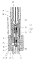
- the cylinder 10 can be shifted to the right, as shown in FIG. Clarify 2 to 4.
- the receiving chamber 16 in the direction of the sliding movement sloping face 92.
- the course of a peripheral surface of a truncated cone corresponds to the corresponding end face 86 of the locking element 62, 64.
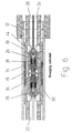
- FIGS. 2 and 3 As a Comparison of FIGS. 2 and 3 further shows is at the beginning of the adjustment of the cylinder 10, the spring element 34 is tensioned more than the spring element 36. Between the end positions on the other hand, there is approximately the same spring tension.
- Unlocking is only possible if not closer to the designated end face of the switching cylinder 28 acts on a working fluid with a force that overcome the force caused by the spring 36 and thus the shift cylinder 28 can be moved in the direction of the partition 30 in order to adjust the axial To enable locking segments 66, 68, whereby the cylinder 10 is released.
- a pressure equalization between the left and right sections 20, 22 of the longitudinal bore 24 of the piston rod 14 then take place if, for example, the compression spring 34 is largely compressed and the compression spring 36 is largely relaxed, each acting on one of the shift cylinders 26 and 28 or the other way around.
- This offers the possibility of several adjustment devices according to the invention to be connected in series, d. H. in a single working fluid circuit without there is a risk that the circuit may be blocked by one of the devices.
- working fluid can flow through the opening 52 formed between the auxiliary piston 44 and the switching cylinder 26 annulus 100 flow another annulus 102, which is between the outer wall of the shift cylinder 26 and inner wall of the piston rod 14 extends. Flows through the annular space 102 then working fluid in the interior 54 of the shift cylinder 26 and passes through the Opening 32 of the partition 30 in the section 22 of the longitudinal bore 24 of the piston rod 14 so as to flow to another piston, not shown.
Landscapes
- Engineering & Computer Science (AREA)
- Mechanical Engineering (AREA)
- Actuator (AREA)
- Fluid-Damping Devices (AREA)
- Vehicle Body Suspensions (AREA)
- Extrusion Moulding Of Plastics Or The Like (AREA)
- Paper (AREA)
Description
- Fig. 1
- eine Einrichtung zum Verstellen und zum Verriegeln eines mit beweglichen Elementen wie Gleisabschnitten verbundenen Zylinders zu Beginn eines Verstellens aus einer ersten (linken) Endlage,
- Fig. 2
- die Einrichtung gemäß Fig. 1, jedoch nach weiterer Bewegung des Zylinders,
- Fig. 3
- die Einrichtung nach den Fig. 1 und bei zwischen Endstellung befindlichem Zylinder,
- Fig. 4
- die Einrichtung nach den Fig. 1 bis 3 bei erreichter zweiter (rechter) Endlage,
- Fig. 5
- die Einrichtung nach den Fig. 1 bis 4 bei erreichter zweiter (rechter) Endlage in ihrer Ruhestellung,
- Fig. 6
- eine den Fig. 1 bis 5 entsprechende Einrichtung bei geklemmter Bewegung,
- Fig. 7
- eine Detaildarstellung eines Schaltzylinders mit Hilfskolben und
- Fig. 8
- ein Ausschnitt einer Kolbenstange mit in dieser axial verschiebbaren Schaltzylinder und Hilfskolben.
Claims (13)
- Einrichtung zum Verstellen sowie Verriegeln in Endlagen von zueinander beweglichen Elementen, insbesondere beweglichen Gleisabschnitten wie Weichen- und Herzstückspitzenteilen, umfassend eine mit einem Arbeitsfluid beaufschlagbare Kolben-Zylinder-Anordnung mit doppelwirkendem Zylinder (10) und ortsfest angeordneter. eine von dem Arbeitsfluid beaufschlagbare Längsbohrung (24) aufweisender Kolbenstange (14), entlang der der Zylinder (10) verschiebbar ist, der seinerseits in den Endlagen entsprechenden Endstellungen verriegelbar ist und von dem ein zum Verstellen des Elements führendes Verbindungselement ausgeht,
dadurch gekennzeichnet, dass innerhalb der Kolbenstange (14) zumindest ein Schaltzylinder (26, 28) axial verschiebbar angeordnet ist, der über ein erstes Federelement (34, 36) entgegen von dem Arbeitsfluid erzeugter Kraftbeaufschlagung verschiebbar ist, und dass die Kolbenstange von der Längsbohrung (24) ausgehend von zumindest einem radial verschiebbaren Verriegelungselement (62, 64, 66, 68) durchsetzt ist, das bei sich in einer Endstellung befindlichem Zylinder (10) bereichsweise in einer Aufnahmekammer (16, 18) von diesem erstreckt und in dieser durch Anliegen an dem Schaltzylinder gehalten ist. - Einrichtung nach Anspruch 1,
dadurch gekennzeichnet, dass innerhalb des vorzugsweise innerhalb der Längsbohrung (24) axial verschiebbaren Schaltzylinders (26, 28) ein Hilfskolben (44, 46) mit axialer Durchbrechung (48) verschiebbar ist, die in einem Stirnbereich in die Längsbohrung (24) der Kolbenstange (14) übergeht und deren anderer Stirnbereich über ein Rückschlagventil (58, 60) verschließbar ist. - Einrichtung nach Anspruch 2,
dadurch gekennzeichnet, dass auf den Hilfskolben (44, 46) ein zweites Federelement (38, 40), insbesondere Tellerfeder zum Abdichten des Hilfskolbens gegenüber dem Schaltzylinder (26, 28) einwirkt. - Einrichtung nach einem der Ansprüche 2 oder 3,
dadurch gekennzeichnet, dass bei fehlender Abdichtung zwischen dem Hilfskolben (44, 46) und dem Schaltzylinder (26, 28) ersterer eine Verbindung zu einem weiteren einer weiteren Endstellung des Zylinders (10) zugeordneten Schaltzylinder bzw. einer weiteren in Reihe geschalteten Einrichtung mit Kolben-Zylinder-Anordnung freigibt. - Einrichtung nach einem der Ansprüche 1 bis 4,
dadurch gekennzeichnet, dass bei sich in einer Endstellung befindlichem Zylinder (10) dieser durch zumindest eines der in der Aufnahmekammer (16, 18) befindlichen und durch einen der Schaltzylinder (26, 28) gehaltenen Verriegelungselemente (62, 64, 66, 68) bei auf jedem Schaltzylinder einwirkendem gleichen oder nahezu gleichen Arbeitsfluiddruck arretierbar ist. - Einrichtung nach einem der Ansprüche 1 bis 5,
dadurch gekennzeichnet, dass von dem Schaltzylinder (26, 28) eine dessen Stellung überwachende Schaltstange ausgeht, die sich zumindest abschnittsweise innerhalb der Längsbohrung der Kolbenstange (14) erstreckt. - Einrichtung nach einem der Ansprüche 1 bis 6,
dadurch gekennzeichnet, dass innerhalb der Kolbenstangenwandung eine Verbindung (78, 80) verläuft, die von einem von einem der Schaltzylinder (26, 28) umgebenden Innenraum (54) zu von einem anderen Schaltzylinder begrenzten und durch die Längsbohrung vorgegebenen Außenraum bei in einer Endstellung arretiertem Zylinder (10) und bei gleicher oder in etwa gleicher Arbeitsfluidbeaufschlagung der Schaltzylinder führt. - Einrichtung nach einem der Ansprüche 1 bis 7,
dadurch gekennzeichnet, dass das Verriegelungselement (62, 64, 66, 68) eine axiale Erstreckung aufweist, die kleiner als die der Aufnahmekammer (16, 18) ist. - Einrichtung nach einem der Ansprüche 1 bis 8,
dadurch gekennzeichnet, dass der Schaltzylinder (26, 28) eine kegelstumpfförmige Stirnfläche aufweist, die mit einer entsprechenden kegelstumpfförmigen Stirnfläche des Verriegelungselements (62, 64, 66, 68) wechselwirkt. - Einrichtung nach Anspruch 9,
dadurch gekennzeichnet, dass die Aufnahmekammer (16, 18) in einem Stirnbereich eine der kegelstumpfförmigen Stirnfläche des Verriegelungselements entsprechende Geometrie aufweist und im gegenüberliegenden Bereich durch eine senkrecht zum Verschiebeweg des Schaltzylinders (26, 28) verlaufende Wandung begrenzt ist. - Einrichtung nach Anspruch 3 oder Anspruch 3 und einem der Ansprüche 4-10,
dadurch gekennzeichnet, dass das erste innerhalb des Schaltzylinders (26, 28) verlaufende Federelement (34, 36) an dem zweiten Federelement (38, 40) wie Tellerfeder abgestützt ist, das zwischen dem Hilfskolben (44, 46) und dem Schaltzylinder eingespannt ist - Einrichtung nach Anspruch 3 oder Anspruch 3 und einem der Anspruche 4-11,
dadurch gekennzeichnet, dass das Rückschlagventil ein von einem dritten Federelement (60) beaufschlagtes Verschlußelement wie Kugel (58) umfasst, wobei das dritte Federelement eine Federkraft aufweist, die kleiner als die des ersten Federelements (34, 36) ist, dessen Federkraft kleiner als die des zweiten Federelements (38, 40) ist. - Anordnung zum Verstellen sowie Verriegeln in Endlage von zumindest zwei beweglichen Elementen, insbesondere beweglichen Gleisabschnitten wie Weichen- und Herzstückspitzenteilen, umfassend mehrere mit einem Arbeitsfluid beaufschlagbare Kolben-Zylinder-Anordnungen jeweils mit doppelwirkendem Zylinder (10) und ortsfest angeordneter, eine von dem Arbeitsfluid beaufschlagbare Längsbohrung aufweisender Kolbenstange (14), entlang der der Zylinder verschiebbar ist, der seinerseits in den Endlagen entsprechenden Endstellungen verriegelbar ist und von dem ein zum Verstellen des Elements führendes Verbindungselement ausgeht,
dadurch gekennzeichnet, dass die Kolben-Zylinder-Anordnungen in Reihe geschaltet sind, dass innerhalb der jeweiligen Kolbenstange (14) zumindest ein Schaltzylinder (26, 28) axial verschiebbar angeordnet ist, der über ein erstes Federelement (34, 36) entgegen von dem Arbeitsfluid erzeugter Kraftbeaufschlagung verschiebbar ist, dass innerhalb des innerhalb der Längsbohrung (24) axial verschiebbaren Schaltzylinders (26, 28) ein Hilfskolben (44, 46) mit axialer Durchbrechung (48) verschiebbar ist, die in einem Stirnbereich in die Längsbohrung (24) der Kolbenstange (14) übergeht und deren anderer Stirnbereich über ein Rückschlagventil (58, 60) verschließbar ist, und dass bei fehlender Abdichtung zwischen dem Hilfskolben (44, 46) und dem Schaltzylinder (26, 28) ersterer eine Verbindung zu einem weiteren (zweiten) einer weiteren Endstellung des Zylinders (10) zugeordneten Schaltzylinder bzw. zu einer weiteren von den in Reihe geschalteten Kolben-Zylinder-Anordnungen freigibt.
Applications Claiming Priority (2)
| Application Number | Priority Date | Filing Date | Title |
|---|---|---|---|
| DE19705294 | 1997-02-12 | ||
| DE19705294A DE19705294A1 (de) | 1997-02-12 | 1997-02-12 | Einrichtung zum Verstellen sowie Verriegeln in Endlagen von zueinander beweglichen Elementen |
Publications (3)
| Publication Number | Publication Date |
|---|---|
| EP0858938A2 EP0858938A2 (de) | 1998-08-19 |
| EP0858938A3 EP0858938A3 (de) | 1999-04-21 |
| EP0858938B1 true EP0858938B1 (de) | 2002-06-05 |
Family
ID=7819992
Family Applications (1)
| Application Number | Title | Priority Date | Filing Date |
|---|---|---|---|
| EP98102337A Expired - Lifetime EP0858938B1 (de) | 1997-02-12 | 1998-02-11 | Einrichtung zum Verstellen sowie Verriegeln in Endlagen von zueinander beweglichen Elementen |
Country Status (3)
| Country | Link |
|---|---|
| EP (1) | EP0858938B1 (de) |
| AT (1) | ATE218460T1 (de) |
| DE (2) | DE19705294A1 (de) |
Families Citing this family (1)
| Publication number | Priority date | Publication date | Assignee | Title |
|---|---|---|---|---|
| US8684318B2 (en) | 2010-09-16 | 2014-04-01 | Spx International Limited | Mechanical lock |
Family Cites Families (8)
| Publication number | Priority date | Publication date | Assignee | Title |
|---|---|---|---|---|
| DE2148645A1 (de) * | 1971-09-29 | 1973-04-05 | Siemens Ag | Hydraulische steuerschaltung fuer auffahrbare elektrohydraulische weichenantriebe |
| DE2557574C3 (de) * | 1975-12-20 | 1987-01-22 | Fabeg Gmbh, 7518 Bretten | Hydraulischer Weichenantrieb |
| DE2744969C3 (de) * | 1977-10-06 | 1987-07-30 | Fabeg Gmbh, 7518 Bretten | Hydraulischer Weichenantrieb |
| DE3106708C1 (de) * | 1981-02-23 | 1982-11-11 | Siemens AG, 1000 Berlin und 8000 München | Innenverschluß-Weichenantrieb |
| US4637579A (en) * | 1983-02-10 | 1987-01-20 | General Signal Corporation | Railroad switch mechanism |
| SI9300651A (en) * | 1992-12-17 | 1994-06-30 | Voest Alpine Eisenbahnsysteme | Device for bolding movable parts of railway switches |
| DE4332493C2 (de) * | 1993-09-24 | 2002-12-12 | Butzbacher Weichenbau Gmbh | Stelleinrichtung |
| AT401763B (de) * | 1994-05-16 | 1996-11-25 | Vae Ag | Einrichtung zum verriegeln von beweglichen weichenteilen |
-
1997
- 1997-02-12 DE DE19705294A patent/DE19705294A1/de not_active Withdrawn
-
1998
- 1998-02-11 EP EP98102337A patent/EP0858938B1/de not_active Expired - Lifetime
- 1998-02-11 DE DE59804269T patent/DE59804269D1/de not_active Expired - Fee Related
- 1998-02-11 AT AT98102337T patent/ATE218460T1/de not_active IP Right Cessation
Also Published As
| Publication number | Publication date |
|---|---|
| ATE218460T1 (de) | 2002-06-15 |
| EP0858938A3 (de) | 1999-04-21 |
| DE19705294A1 (de) | 1998-08-13 |
| EP0858938A2 (de) | 1998-08-19 |
| DE59804269D1 (de) | 2002-07-11 |
Similar Documents
| Publication | Publication Date | Title |
|---|---|---|
| DE69411383T2 (de) | Hydraulischer bohrlochschlagschieber mit wartezeitreduzierung | |
| EP0381069A1 (de) | Kupplungsmuffe für hydraulische Leitungsverbindung | |
| DE10234482B3 (de) | Vorrichtung zum Antrieb für Doppelsitzventile | |
| DE102010008167B4 (de) | Schieberventil eines Türbetätigers | |
| EP3814649A2 (de) | Selbstnachstellender kupplungssteller | |
| DE102019103998A1 (de) | Pleuel einer Verbrennungskraftmaschine zur Änderung des Verdichtungsverhältnisses | |
| DE10147229A1 (de) | Zugfeder für Klappe an einem Kraftfahrzeug | |
| DE3807669C2 (de) | ||
| EP1613875B1 (de) | Kolbeneinrichtung und mit einer kolbeneinrichtung ausgeführte kolben-zylinder-anordnung | |
| EP0858938A2 (de) | Einrichtung zum Verstellen sowie Verriegeln in Endlagen von zueinander beweglichen Elementen | |
| EP3344881B1 (de) | Hydromechanischer arretierungszylinder und hydraulisches steuersystem zu dessen betätigung | |
| WO2024156434A1 (de) | Mechanische sperrvorrichtung für einen hydraulikzylinder und hydraulikzylinder mit einer solchen | |
| DE3506596A1 (de) | Steuerventil zum steuern der druckbeaufschlagung eines hydraulikstellgliedes | |
| DE10356596B3 (de) | Verriegelungszylinder | |
| EP1416165A2 (de) | Pneumatischer Stellantrieb | |
| EP1517068A2 (de) | Kraftfahrzeuggetriebe-Stellvorrichtung | |
| EP2318742B1 (de) | Hydraulische ventilvorrichtung | |
| EP2157348A1 (de) | Bistabile Betätigungsvorrichtung für ein Ventil | |
| DE2450330C3 (de) | Doppelhydraulischer Stellantrieb | |
| DE2915505A1 (de) | Kraftbegrenzer fuer eine stellstange | |
| DE102021202897A1 (de) | Aktuator zum Betätigen einer Parksperre | |
| EP0224787B1 (de) | Nachstellvorrichtung für Bremsgestänge von Schienenfahrzeugen | |
| DE2002718A1 (de) | Servo-Betaetigungsvorrichtung | |
| DE10004913A1 (de) | Hochdruckregelventil | |
| EP1725794A1 (de) | Vorrichtung zum antrieb eines doppelsitzventils |
Legal Events
| Date | Code | Title | Description |
|---|---|---|---|
| PUAI | Public reference made under article 153(3) epc to a published international application that has entered the european phase |
Free format text: ORIGINAL CODE: 0009012 |
|
| AK | Designated contracting states |
Kind code of ref document: A2 Designated state(s): AT CH DE ES FR GB IT LI NL |
|
| AX | Request for extension of the european patent |
Free format text: AL;LT;LV;MK;RO;SI |
|
| RAP1 | Party data changed (applicant data changed or rights of an application transferred) |
Owner name: BWG BUTZBACHER WEICHENBAU GESELLSCHAFT MBH & CO. K |
|
| PUAL | Search report despatched |
Free format text: ORIGINAL CODE: 0009013 |
|
| AK | Designated contracting states |
Kind code of ref document: A3 Designated state(s): AT BE CH DE DK ES FI FR GB GR IE IT LI LU MC NL PT SE |
|
| AX | Request for extension of the european patent |
Free format text: AL;LT;LV;MK;RO;SI |
|
| 17P | Request for examination filed |
Effective date: 19990512 |
|
| AKX | Designation fees paid |
Free format text: AT CH DE ES FR GB IT LI NL |
|
| GRAG | Despatch of communication of intention to grant |
Free format text: ORIGINAL CODE: EPIDOS AGRA |
|
| 17Q | First examination report despatched |
Effective date: 20010824 |
|
| GRAG | Despatch of communication of intention to grant |
Free format text: ORIGINAL CODE: EPIDOS AGRA |
|
| GRAG | Despatch of communication of intention to grant |
Free format text: ORIGINAL CODE: EPIDOS AGRA |
|
| GRAH | Despatch of communication of intention to grant a patent |
Free format text: ORIGINAL CODE: EPIDOS IGRA |
|
| RAP1 | Party data changed (applicant data changed or rights of an application transferred) |
Owner name: BWG GMBH & CO. KG |
|
| GRAH | Despatch of communication of intention to grant a patent |
Free format text: ORIGINAL CODE: EPIDOS IGRA |
|
| GRAA | (expected) grant |
Free format text: ORIGINAL CODE: 0009210 |
|
| AK | Designated contracting states |
Kind code of ref document: B1 Designated state(s): AT CH DE ES FR GB IT LI NL |
|
| REF | Corresponds to: |
Ref document number: 218460 Country of ref document: AT Date of ref document: 20020615 Kind code of ref document: T |
|
| REG | Reference to a national code |
Ref country code: GB Ref legal event code: FG4D Free format text: NOT ENGLISH |
|
| REG | Reference to a national code |
Ref country code: CH Ref legal event code: EP |
|
| REF | Corresponds to: |
Ref document number: 59804269 Country of ref document: DE Date of ref document: 20020711 |
|
| GBT | Gb: translation of ep patent filed (gb section 77(6)(a)/1977) |
Effective date: 20020805 |
|
| ET | Fr: translation filed | ||
| PG25 | Lapsed in a contracting state [announced via postgrant information from national office to epo] |
Ref country code: ES Free format text: LAPSE BECAUSE OF FAILURE TO SUBMIT A TRANSLATION OF THE DESCRIPTION OR TO PAY THE FEE WITHIN THE PRESCRIBED TIME-LIMIT Effective date: 20021220 |
|
| PG25 | Lapsed in a contracting state [announced via postgrant information from national office to epo] |
Ref country code: AT Free format text: LAPSE BECAUSE OF NON-PAYMENT OF DUE FEES Effective date: 20030211 |
|
| PG25 | Lapsed in a contracting state [announced via postgrant information from national office to epo] |
Ref country code: LI Free format text: LAPSE BECAUSE OF NON-PAYMENT OF DUE FEES Effective date: 20030228 Ref country code: CH Free format text: LAPSE BECAUSE OF NON-PAYMENT OF DUE FEES Effective date: 20030228 |
|
| PLBE | No opposition filed within time limit |
Free format text: ORIGINAL CODE: 0009261 |
|
| STAA | Information on the status of an ep patent application or granted ep patent |
Free format text: STATUS: NO OPPOSITION FILED WITHIN TIME LIMIT |
|
| 26N | No opposition filed |
Effective date: 20030306 |
|
| REG | Reference to a national code |
Ref country code: CH Ref legal event code: PL |
|
| PGFP | Annual fee paid to national office [announced via postgrant information from national office to epo] |
Ref country code: DE Payment date: 20060214 Year of fee payment: 9 |
|
| PGFP | Annual fee paid to national office [announced via postgrant information from national office to epo] |
Ref country code: NL Payment date: 20060215 Year of fee payment: 9 |
|
| PGFP | Annual fee paid to national office [announced via postgrant information from national office to epo] |
Ref country code: FR Payment date: 20060216 Year of fee payment: 9 |
|
| PGFP | Annual fee paid to national office [announced via postgrant information from national office to epo] |
Ref country code: IT Payment date: 20060228 Year of fee payment: 9 |
|
| GBPC | Gb: european patent ceased through non-payment of renewal fee |
Effective date: 20070211 |
|
| NLV4 | Nl: lapsed or anulled due to non-payment of the annual fee |
Effective date: 20070901 |
|
| REG | Reference to a national code |
Ref country code: FR Ref legal event code: ST Effective date: 20071030 |
|
| PG25 | Lapsed in a contracting state [announced via postgrant information from national office to epo] |
Ref country code: NL Free format text: LAPSE BECAUSE OF NON-PAYMENT OF DUE FEES Effective date: 20070901 Ref country code: DE Free format text: LAPSE BECAUSE OF NON-PAYMENT OF DUE FEES Effective date: 20070901 |
|
| PG25 | Lapsed in a contracting state [announced via postgrant information from national office to epo] |
Ref country code: GB Free format text: LAPSE BECAUSE OF NON-PAYMENT OF DUE FEES Effective date: 20070211 Ref country code: FR Free format text: LAPSE BECAUSE OF NON-PAYMENT OF DUE FEES Effective date: 20070228 |
|
| PGFP | Annual fee paid to national office [announced via postgrant information from national office to epo] |
Ref country code: GB Payment date: 20060221 Year of fee payment: 9 |
|
| PG25 | Lapsed in a contracting state [announced via postgrant information from national office to epo] |
Ref country code: IT Free format text: LAPSE BECAUSE OF NON-PAYMENT OF DUE FEES Effective date: 20070211 |