EP0858849A1 - Tensioning device for an internal high-pressure forming tool - Google Patents
Tensioning device for an internal high-pressure forming tool Download PDFInfo
- Publication number
- EP0858849A1 EP0858849A1 EP98102249A EP98102249A EP0858849A1 EP 0858849 A1 EP0858849 A1 EP 0858849A1 EP 98102249 A EP98102249 A EP 98102249A EP 98102249 A EP98102249 A EP 98102249A EP 0858849 A1 EP0858849 A1 EP 0858849A1
- Authority
- EP
- European Patent Office
- Prior art keywords
- clamping device
- clamping
- tool
- carrier
- jaw
- Prior art date
- Legal status (The legal status is an assumption and is not a legal conclusion. Google has not performed a legal analysis and makes no representation as to the accuracy of the status listed.)
- Granted
Links
Images


Classifications
-
- B—PERFORMING OPERATIONS; TRANSPORTING
- B21—MECHANICAL METAL-WORKING WITHOUT ESSENTIALLY REMOVING MATERIAL; PUNCHING METAL
- B21D—WORKING OR PROCESSING OF SHEET METAL OR METAL TUBES, RODS OR PROFILES WITHOUT ESSENTIALLY REMOVING MATERIAL; PUNCHING METAL
- B21D26/00—Shaping without cutting otherwise than using rigid devices or tools or yieldable or resilient pads, i.e. applying fluid pressure or magnetic forces
- B21D26/02—Shaping without cutting otherwise than using rigid devices or tools or yieldable or resilient pads, i.e. applying fluid pressure or magnetic forces by applying fluid pressure
- B21D26/021—Deforming sheet bodies
- B21D26/025—Means for controlling the clamping or opening of the moulds
-
- B—PERFORMING OPERATIONS; TRANSPORTING
- B21—MECHANICAL METAL-WORKING WITHOUT ESSENTIALLY REMOVING MATERIAL; PUNCHING METAL
- B21D—WORKING OR PROCESSING OF SHEET METAL OR METAL TUBES, RODS OR PROFILES WITHOUT ESSENTIALLY REMOVING MATERIAL; PUNCHING METAL
- B21D26/00—Shaping without cutting otherwise than using rigid devices or tools or yieldable or resilient pads, i.e. applying fluid pressure or magnetic forces
- B21D26/02—Shaping without cutting otherwise than using rigid devices or tools or yieldable or resilient pads, i.e. applying fluid pressure or magnetic forces by applying fluid pressure
- B21D26/033—Deforming tubular bodies
- B21D26/039—Means for controlling the clamping or opening of the moulds
Definitions
- the invention relates to a clamping device for holding together parts of a mold in hydroforming, with a jaw forming Tool carrier, one offset from the tool carrier to the working position of the mold extending tension holder, one arranged opposite the tool carrier movable jaws, and one to hold the mold parts together between the movable jaw and the tool carrier the movable Wedge clamping jaws between the tension bracket and the mold Bayonet clamping device.
- Such clamping devices are used to hold parts of a molding tool together known in hydroforming, in which the tool holder together with the Tension clamp holder are cup-shaped with the pot base as a tool holder.
- the vertical, cylindrical wall of the pot has openings for the insertion of an to be formed Pressurized fluid supply lines to be attached as well as for the loading of the mold with a workpiece to be formed.
- One of the tools is the clamping jaw in the released state of the bayonet clamping device to be raised so that the pot-shaped tool holder is accessible from above is. The tool and any spacers are then vertically into the tool holder from above introduce.
- the tensioning device according to the invention that solves this problem is characterized in that that the tension clamp at least one for feeding the mold into the Working position in a direction perpendicular to the clamping direction suitable feed opening having.
- the tension device could e.g. two are at a distance from each other from the tool carrier have extending plates, so that a tool from two sides between the plates could be arranged on the tool carrier.
- the tension bracket is of a particular plate-shaped Tool carrier extending support columns and one on the support columns at a distance carrier platform attached to the tool carrier with an opening for the movable jaws and hooking parts arranged around the opening of the bayonet clamping device, with the largest possible feed openings are formed between the support columns.
- the clamping jaw In the clamping position, the clamping jaw then projects downwards from the carrier platform, whereby it is arranged via the bayonet clamping device between one on the tool carrier Tool and the carrier platform is wedged.
- the distance of the carrier platform from the tool carrier to Setting of different clamping starting positions varies, i.e. the carrier platform raised or be lowered.
- the device has a lifting device for lifting and lowering the jaws, this lifting device simultaneously Holder of the jaw can serve as long as the jaw is not against Form tool is applied.
- this lifting device which e.g. also through one or more hydraulic cylinders can be formed with one with the jaws connected piston rod on another arranged above the carrier platform Carrier platform attached, advantageously the further carrier platform against the Breakthrough carrier platform is supported.
- the latter measure ensures that with an adjustment of the clamping starting position by height adjustment the carrier platform showing the breakthrough no corresponding change in the Lifting range of the lifting device is required.
- the device according to the invention also expediently has devices for vertical Guidance of the jaw moved by the lifting device, these guides essentially by guide rods protruding from the carrier platform with the opening and guide bushings are formed, which on one with the jaws attached to the upper side of the plate, which projects above the jaws are.
- the bayonet clamping device has a bayonet ring seated on the clamping jaw, the bayonet ring in particular rests on an annular shoulder formed on the clamping jaw.
- the tension of the clamping jaw via such a bayonet ring that can be rotated against the clamping jaw has the bayonet hooking parts directly attached to the jaw.
- the Bayonet clamping device preferably a plurality of a ring gear around the bayonet ring or the bayonet hooks forming the opening in the carrier platform.
- the bayonet ring proves in accordance with another expedient construction solution
- attack bearings for hydraulic rotary actuators wherein these attack camps are guided through openings formed in the above-mentioned plate, the plate being provided with counter bearings for the hydraulic actuators can.
- the clamping jaw has the a counter-tensioning device one by fluid pressure, e.g. the working pressure of the device, pressurizable back pressure chamber due to the deformation of the mold cavity can be counteracted, e.g. can occur that the jaws yields under the influence of the pressing forces occurring during the forming process and the tool parts move apart.
- the back pressure chamber could also in a short-stroke cylinder acting on a clamping jaw and / or the tool be educated.
- a part of the clamping jaw lying against the tool is against the
- the remaining jaws are provided movably and have one in the manner of a pressure piston trained section which can be acted upon by the fluid pressure in the counter-chamber on. With suitable pressurization, the jaws can then give way compensate by moving the movable section relative to the jaw accordingly advances, holding the tool parts in place.
- the back pressure chamber is useful with a flexible sealing lining, in particular formed by a plastic membrane provided so that no special for sealing the pressure piston section Measures need to be taken. Through the possibility of compensation Via the back pressure chamber there is the possibility for the stability of the clamping device to make crucial parts less stable because the jaws give way to a certain extent can be accepted.
- a construction of the support platform that is particularly useful in this context provides that the platform has a breakthrough with the interlocking Ring part, the socket parts connecting the platform with the support columns and the socket parts has plate struts connecting to the ring part and thus relatively is lightly constructed.
- the tool carrier has undercut grooves for the clamping attachment of tool parts.
- Such grooves in particular provided at a close distance, in which hookable mounting clamps are displaceable, allow almost any hooking arrangement of these clamps according to different dimensions of tool parts.
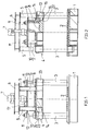
- FIGS. 1 to 4 With the reference numeral 1 in FIGS. 1 to 4 is one in the embodiment shown called square tool carrier plate, undercut in its mounting surface Tension grooves 2 are provided. From each of the four corner areas of the tool carrier plate 1 extends a support column 3. Is at a distance from the tool holder 1 A carrier platform 4 is attached to the support columns 3 above the tool carrier. In the exemplary embodiment shown, the carrier platform 4 is rigid on the support columns 3 attached. Instead, it could also be provided that the carrier platform 4 on the support columns 3 slidable and in different height positions above the tool carrier plate 1 can be determined.
- a total of four vertical supports 5 with a double-T profile extend from the support platform 4, which support a further carrier platform 6 arranged above the carrier platform 4.
- a hydraulic cylinder 7 is held, which acts as a lifting device for a clamping jaw attached to the cylinder rod 9 of the hydraulic cylinder 7 8 serves.
- At the top of the jaw 8 is a horizontally on both sides above the jaws 8 protruding plate 10 attached, in the middle of a recess for the implementation the cylinder rod 9 of the hydraulic cylinder 7 is provided. Horizontally offset from that Clamping jaws 8 are arranged on the plate 10 a total of four sockets 11, in which the support platform 4 are guided upwardly projecting guide rods 12.
- the bayonet ring 13 has hooking parts of a bayonet clamping device a plurality of interlocking teeth 14 on the one the clamping ring form a ring gear on the underside that surrounds it on the outside. One pointing upwards Interlocking surface of the teeth is slightly chamfered.
- the bayonet ring is 17 with assault bearings connected for rotary actuation. which project upwards through openings in the plate 10. Hydraulic cylinders acting on the attack bearings 17 are not shown in FIGS. 1 to 4.
- the carrier platform 4 has a ring part 15 with one of the hooking teeth 14 of the bayonet ring corresponding counter teeth, the teeth 16 of the counter teeth provided with a slightly sloping hooking surface pointing downwards are.
- a tool is attached to the tool carrier plate 1 with the aid of the fastening grooves 2 a lower part facing the tool carrier 1 and a facing the clamping jaw 8 Upper part attached. You can use the between the mounting columns existing space can be used.
- FIGS. 1 and 2 shown raised position of the clamping jaw 8, in which the teeth 14 of the clamping ring 13 stand between the teeth 16 of the ring part 15 of the carrier platform 4 and the Clamping jaws 8 ends approximately flush with the ring part 16 at the bottom.
- the clamping jaw 8 is lowered via the lifting device 7.
- an appropriate height adjustment of the support platform 4 was previously ensured that the top of the upper part of the tool in such a Height is that a suitable starting position for clamping the jaws given is.
- This suitable starting position is realized when twisting of the clamping ring 13, the inclined interlocking surfaces come to bear against one another and so via the bayonet clamping ring 13 a corresponding one exerted on the tool Clamping force can be generated.
- the clamping device Holds tool parts together.
- FIG. 5 where the same or equivalent parts with the same reference number, however, provided with the letter a.
- FIG. 5 differs from the previous embodiment in that another is provided for holding a hydraulic cylinder 7a Platform 6a is not supported against an underlying platform 4a, but Support columns 3a extended and used to hold the further support platform 6a are.
- a jaw 8a Back pressure chamber which can be acted upon by a pressure fluid via a connecting channel 21 18 is provided, in which a sealing, flexible inner lining 19 from a Plastic material is arranged.
- the jaw 8a also has a lower movable Part 20, of which a portion in the jaw 8a in the manner of a pressure piston is guided flexibly. Holding the movable part 20 on the jaw 8a End stops are not shown in FIG. 5.
- the back pressure chamber 18 is via the pressure connection channel 21 Fluid lines, not shown, are pressurized, e.g. with that for hydroforming working pressure used.
- Fluid lines not shown, are pressurized, e.g. with that for hydroforming working pressure used.
Abstract
Description
Die Erfindung betrifft eine Spannvorrichtung zum Zusammenhalten von Teilen eines Formwerkzeugs beim Innenhochdruckumformen, mit einem einen Spannbacken bildenden Werkzeugträger, einer sich versetzt zur Arbeitsposition des Formwerkzeugs von dem Werkzeugträger erstreckenden Zugspannhalterung, einem gegenüber dem Werkzeugträger angeordneten beweglichen Spannbacken, und einer zum Zusammenhalten der Formwerkzeugteile zwischen dem beweglichen Spannbacken und dem Werkzeugträger den beweglichen Spannbacken zwischen der Zugspannhalterung und dem Formwerkzeug verkeilenden Bajonettspanneinrichtung.The invention relates to a clamping device for holding together parts of a mold in hydroforming, with a jaw forming Tool carrier, one offset from the tool carrier to the working position of the mold extending tension holder, one arranged opposite the tool carrier movable jaws, and one to hold the mold parts together between the movable jaw and the tool carrier the movable Wedge clamping jaws between the tension bracket and the mold Bayonet clamping device.
Es sind derartige Spannvorrichtungen zum Zusammenhalten von Teilen eines Formwerkzeugs beim Innenhochdruckumformen bekannt, bei denen der Werkzeugträger zusammen mit der Zugspannhalterung topfförmig mit dem Topfboden als Werkzeugträger ausgebildet sind. In der vertikalen, zylindrischen Topfwand sind Öffnungen für die Einführung von an ein umzuformendes Werkstück anzusetzenden Druckfluidzuführungsleitungen sowie für die Beschickung des Formwerkzeugs mit einem umzuformenden Werkstück vorgesehen. Zur Installation eines Werkzeugs ist der Spannbacken im gelösten Zustand der Bajonettspanneinrichtung so weit anzuheben, daß der topfförmige Werkzeughalter von oben her zugänglich ist. Das Werkzeug und ggf. Abstandsstücke sind dann vertikal von oben in den Werkzeughalter einzuführen.Such clamping devices are used to hold parts of a molding tool together known in hydroforming, in which the tool holder together with the Tension clamp holder are cup-shaped with the pot base as a tool holder. In The vertical, cylindrical wall of the pot has openings for the insertion of an to be formed Pressurized fluid supply lines to be attached as well as for the loading of the mold with a workpiece to be formed. For installation One of the tools is the clamping jaw in the released state of the bayonet clamping device to be raised so that the pot-shaped tool holder is accessible from above is. The tool and any spacers are then vertically into the tool holder from above introduce.
Es ist die Aufgabe der vorliegenden Erfindung, eine neue Spannvorrichtung der oben genannten Art zu schaffen, die insbesondere in Bezug auf Werkzeuginstallationen leichter zu handhaben ist. It is the object of the present invention to provide a new clamping device of the above Art to create that easier, especially with regard to tool installations handle.
Die diese Aufgabe lösende Spannvorrichtung nach der Erfindung ist dadurch gekennzeichnet, daß die Zugspannhalterung wenigstens eine, zur Zuführung des Formwerkzeugs in die Arbeitsposition in einer Richtung senkrecht zur Spannrichtung geeignete Zuführungsöffnung aufweist.The tensioning device according to the invention that solves this problem is characterized in that that the tension clamp at least one for feeding the mold into the Working position in a direction perpendicular to the clamping direction suitable feed opening having.
Durch die erfindungsgemäße Gestaltung der Zugspanneinrichtung derart, daß die Werkzeugteile dem Werkzeugträger seitlich horizontal zuführbar sind, ergibt sich gegenüber der nach dem Stand der Technik praktizierten Zuführung von oben eine deutliche Erleichterung der Werkzeugmontage.The inventive design of the tensioning device such that the tool parts the tool carrier can be fed horizontally from the side, results in comparison with the according to the prior art, feeding from above practiced a significant relief tool assembly.
Die Zugspanneinrichtung könnte z.B. zwei sich im Abstand zueinander von dem Werkzeugträger erstreckende Platten aufweisen, so daß ein Werkzeug von zwei Seiten her zwischen den Platten auf dem Werkzeugträger angeordnet werden könnte.The tension device could e.g. two are at a distance from each other from the tool carrier have extending plates, so that a tool from two sides between the plates could be arranged on the tool carrier.
Größtmöglichen Installationsfreiraum ergibt sich in einer bevorzugten Ausführungsform der Erfindung, in welcher die Zugspannhalterung sich von einem insbesondere plattenförmigen Werkzeugträger erstreckende Halterungssäulen und eine an den Halterungssäulen im Abstand zu dem Werkzeugträger angebrachte Trägerplattform mit einem Durchbruch für den beweglichen Spannbacken und um den Durchbruch herum angeordneten Verhakungsteilen der Bajonettspanneinrichtung aufweist, wobei hier größtmögliche Zuführungsöffnungen zwischen den Halterungssäulen gebildet sind.The largest possible installation space results in a preferred embodiment of the Invention, in which the tension bracket is of a particular plate-shaped Tool carrier extending support columns and one on the support columns at a distance carrier platform attached to the tool carrier with an opening for the movable jaws and hooking parts arranged around the opening of the bayonet clamping device, with the largest possible feed openings are formed between the support columns.
In der Spannstellung steht der Spannbacken dann nach unten von der Trägerplattform vor, wobei er über die Bajonettspanneinrichtung zwischen einem auf dem Werkzeugträger angeordneten Werkzeug und der Trägerplattform verkeilt ist. In einer zweckmäßigen Ausführungsform der Erfindung kann der Abstand der Trägerplattform von dem Werkzeugträger zur Einstellung unterschiedlicher Spannausgangspositionen variiert, d.h. die Trägerplattform gehoben oder abgesenkt werden.In the clamping position, the clamping jaw then projects downwards from the carrier platform, whereby it is arranged via the bayonet clamping device between one on the tool carrier Tool and the carrier platform is wedged. In an expedient embodiment the distance of the carrier platform from the tool carrier to Setting of different clamping starting positions varies, i.e. the carrier platform raised or be lowered.
In einer zweckmäßigen Ausführungsform weist die Vorrichtung eine Hubeinrichtung zum Anheben und Absenken des Spannbackens auf, wobei diese Hubeinrichtung gleichzeitig zur Halterung des Spannbackens dienen kann, solange der Spannbacken nicht gegen ein Formwerkzeug anliegt.In an expedient embodiment, the device has a lifting device for lifting and lowering the jaws, this lifting device simultaneously Holder of the jaw can serve as long as the jaw is not against Form tool is applied.
Gemäß einer bevorzugten konstruktiven Lösung ist diese Hubeinrichtung, die z.B. auch durch einen oder mehrere Hydraulikzylinder gebildet sein kann, mit einer mit dem Spannbacken verbundenen Kolbenstange an einer über der Trägerplattform angeordneten weiteren Trägerplattform angebracht wobei vorteilhaft die weitere Trägerplattform gegen die den Durchbruch aufweisende Trägerplattform abgestützt ist. Durch letztere Maßnahme ist gewährleistet, daß bei einer Verstellung der Spannausgangsposition durch Höhenverstellung der den Durchbruch aufweisenden Trägerplattform keine entsprechende Veränderung des Hubbereichs der Hubeinrichtung erforderlich ist.According to a preferred constructive solution, this lifting device, which e.g. also through one or more hydraulic cylinders can be formed with one with the jaws connected piston rod on another arranged above the carrier platform Carrier platform attached, advantageously the further carrier platform against the Breakthrough carrier platform is supported. The latter measure ensures that with an adjustment of the clamping starting position by height adjustment the carrier platform showing the breakthrough no corresponding change in the Lifting range of the lifting device is required.
Zweckmäßig weist die erfindungsgemäße Vorrichtung ferner Einrichtungen zur vertikalen Führung des durch die Hubeinrichtung bewegten Spannbackens auf, wobei diese Führungen im wesentlichen durch von der Trägerplattform mit dem Durchbruch vorstehende Führungsstangen und Führungsbuchsen gebildet sind, welche an einer mit dem Spannbacken an dessen Oberseiten verbundenen, über den Spannbacken überstehenden Platte angebracht sind.The device according to the invention also expediently has devices for vertical Guidance of the jaw moved by the lifting device, these guides essentially by guide rods protruding from the carrier platform with the opening and guide bushings are formed, which on one with the jaws attached to the upper side of the plate, which projects above the jaws are.
In weiterer vorteilhafter Ausgestaltung der Erfindung weist die Bajonettspanneinrichtung einen auf dem Spannbacken aufsitzenden Bajonettring auf, wobei der Bajonettring insbesondere auf einer an dem Spannbacken gebildeten Ringschulter aufsitzt. Die Verspannung des Spannbackens über einen solchen, gegen den Spannbacken drehbaren Bajonettring hat gegenüber direkt am Spannbacken angebrachten Bajonettverhakungsteilen den wesentlichen Vorteil, daß zur Verkeilung des Spannbackens dieser nicht selbst gedreht zu werden braucht, was in Anbetracht der Preßanlage gegen das Werkzeug nachteilig wäre.In a further advantageous embodiment of the invention, the bayonet clamping device has a bayonet ring seated on the clamping jaw, the bayonet ring in particular rests on an annular shoulder formed on the clamping jaw. The tension of the clamping jaw via such a bayonet ring that can be rotated against the clamping jaw has the bayonet hooking parts directly attached to the jaw Significant advantage that the wedge of the clamping jaw is not turned by itself are needed, which would be disadvantageous in view of the press system against the tool.
Zur Gewährleistung kurzer Spannwege bei hoher zu übertragender Spannkraft weist die Bajonettspanneinrichtung vorzugsweise eine Vielzahl von einen Zahnkranz um den Bajonettring bzw. den Durchbruch in der Trägerplattform bildenden Bajonettverhakungen auf.To ensure short clamping distances with high clamping force to be transmitted, the Bayonet clamping device preferably a plurality of a ring gear around the bayonet ring or the bayonet hooks forming the opening in the carrier platform.
Entsprechend einer weiteren zweckmäßigen Konstruktionslösung weist der Bajonettring nach oben vorstehende Angriffslager für hydraulische Drehbetätigungseinrichtungen auf, wobei diese Angriffslager durch in der obengenannten Platte gebildete Durchbrüche geführt sind, wobei die Platte mit Gegenlagern für die Hydraulikbetätigungseinrichtungen versehen sein kann.The bayonet ring proves in accordance with another expedient construction solution Above above attack bearings for hydraulic rotary actuators, wherein these attack camps are guided through openings formed in the above-mentioned plate, the plate being provided with counter bearings for the hydraulic actuators can.
In einer besonders bevorzugten Ausführungsform der Erfindung weist der Spannbacken als eine Gegenspanneinrichtung eine durch Fluiddruck, z.B. den Arbeitsdruck der Vorrichtung, beaufschlagbare Gegendruckkammer auf, durch die Deformationen des Formhohlraums entgegengewirkt werden kann, welche z.B. dadurch auftreten können, daß der Spannbacken unter der Einwirkung der beim Umformvorgang auftretenden Preßkräfte nachgibt und die Werkzeugteile sich dadurch auseinanderbewegen. Die Gegendruckkammer könnte auch in einem auf einen Spannbacken oder/und das Werkzeug einwirkenden Kurzhubzylinder gebildet sein. In a particularly preferred embodiment of the invention, the clamping jaw has the a counter-tensioning device one by fluid pressure, e.g. the working pressure of the device, pressurizable back pressure chamber due to the deformation of the mold cavity can be counteracted, e.g. can occur that the jaws yields under the influence of the pressing forces occurring during the forming process and the tool parts move apart. The back pressure chamber could also in a short-stroke cylinder acting on a clamping jaw and / or the tool be educated.
Vorzugsweise ist ein gegen das Werkzeug anliegender Teil des Spannbackens gegen den übrigen Spannbacken beweglich vorgesehen und weist einen in der Art eines Druckkolbens ausgebildeten, durch den Fluiddruck in der Gegenkammer beaufschlagbaren Abschnitt auf. Bei geeigneter Druckbeaufschlagung läßt sich so ein Nachgeben des Spannbackens kompensieren, indem der bewegliche Abschnitt relativ zum Spannbacken entsprechend vorrückt und so die Werkzeugteile an Ort und Stelle hält. Zweckmäßig ist die Gegendruckkammer mit einer flexiblen, insbesondere durch eine Kunststoffmembran gebildeten Dichtungsauskleidung versehen, so daß zur Abdichtung des Druckkolbenabschnitts keine besonderen Maßnahmen getroffen zu werden brauchen. Durch die Kompensationsmöglichkeit über die Gegendruckkammer besteht die Möglichkeit, für die Stabilität der Spannvorrichtung maßgebende Teile weniger stabil auszubilden, weil ein Nachgeben des Spannbackens in bestimmtem Umfang in Kauf genommen werden kann.Preferably, a part of the clamping jaw lying against the tool is against the The remaining jaws are provided movably and have one in the manner of a pressure piston trained section which can be acted upon by the fluid pressure in the counter-chamber on. With suitable pressurization, the jaws can then give way compensate by moving the movable section relative to the jaw accordingly advances, holding the tool parts in place. The back pressure chamber is useful with a flexible sealing lining, in particular formed by a plastic membrane provided so that no special for sealing the pressure piston section Measures need to be taken. Through the possibility of compensation Via the back pressure chamber there is the possibility for the stability of the clamping device to make crucial parts less stable because the jaws give way to a certain extent can be accepted.
Eine insbesondere in diesem Zusammenhang zweckmäßige Konstruktion der Trägerplattform sieht vor, daß die Plattform ein den Durchbruch mit den Verhakungen aufweisenden Ringteil, die Plattform mit den Halterungssäulen verbindende Buchsenteile und die Buchsenteile mit dem Ringteil verbindende Plattenverstrebungen aufweist und somit verhältnismäßig leicht konstruiert ist.A construction of the support platform that is particularly useful in this context provides that the platform has a breakthrough with the interlocking Ring part, the socket parts connecting the platform with the support columns and the socket parts has plate struts connecting to the ring part and thus relatively is lightly constructed.
In weiterer vorteilhafter Ausgestaltung der Erfindung kann vorgesehen sein, daß der Werkzeugträger hinterschnittene Rillen für die Spannbefestigung von Werkzeugteilen aufweist. Solche insbesondere in engem Abstand vorgesehene Rillen, in denen verhakbare Halterungsklemmen verschiebbar sind, erlauben eine nahezu beliebige Verhakungsanordnung dieser Klemmen entsprechend unterschiedlichen Maßen von Werkzeugteilen.In a further advantageous embodiment of the invention it can be provided that the tool carrier has undercut grooves for the clamping attachment of tool parts. Such grooves, in particular provided at a close distance, in which hookable mounting clamps are displaceable, allow almost any hooking arrangement of these clamps according to different dimensions of tool parts.
Die Erfindung soll nun anhand von Ausführungsbeispielen und der beiliegenden, sich auf diese Ausführungsbeispiele beziehenden Zeichnungen näher erläutert und beschrieben werden. Es zeigen:
- Fig. 1
- ein Ausführungsbeispiel für eine erfindungsgemäße Vorrichtung in einer Seitenansicht,
- Fig. 2
- die Vorrichtung von Fig. 1 in einer zu der Seitenansicht von Fig. 1 senkrechten Seitenansicht (teilweise geschnitten),
- Fig. 3
- die Vorrichtung gemäß den Fig. 1 und 2 in einer Draufsicht mit einem Teilschnitt in einer ersten Ebene,
- Fig. 4
- die Vorrichtung gemäß den Fig. 1 und 2 in einer Draufsicht mit einem Teilschnitt in einer zweiten Ebene, und
- Fig. 5
- ein weiteres Ausführungsbeispiel für eine erfindungsgemäße Vorrichtung.
- Fig. 1
- an embodiment of a device according to the invention in a side view,
- Fig. 2
- 1 in a side view perpendicular to the side view of FIG. 1 (partially cut),
- Fig. 3
- 1 and 2 in a plan view with a partial section in a first plane,
- Fig. 4
- the device of FIGS. 1 and 2 in a plan view with a partial section in a second plane, and
- Fig. 5
- a further embodiment for a device according to the invention.
Mit dem Bezugszeichen 1 ist in den Fig. 1 bis 4 eine in dem gezeigten Ausführungsbeispiel
quadratische Werkzeugträgerplatte bezeichnet, in deren Befestigungsoberfläche hinterschnittene
Spannrillen 2 vorgesehen sind. Von jedem der vier Eckbereiche der Werkzeugträgerplatte
1 erstreckt sich eine Halterungssäule 3. Im Abstand zu dem Werkzeugträger 1 ist
über dem Werkzeugträger an den Halterungssäulen 3 eine Trägerplattform 4 angebracht. In
dem gezeigten Ausführungsbeispiel ist die Trägerplattform 4 an den Halterungssäulen 3 starr
befestigt. Stattdessen könnte auch vorgesehen sein, daß die Trägerplattform 4 an den Halterungssäulen
3 verschiebbar und in verschiedenen Höhenpositionen über der Werkzeugträgerplatte
1 festlegbar ist.With the
Von der Trägerplattform 4 erstrecken sich insgesamt vier Vertikalträger 5 mit einem Doppel-T-Profil,
welche eine über der Trägerplattform 4 angeordnete weitere Trägerplattform 6 abstützen.A total of four vertical supports 5 with a double-T profile extend from the
In der Mitte der weiteren Trägerplattform 6 ist ein Hydraulikzylinder 7 gehaltert, der als Hubeinrichtung
für einen an der Zylinderstange 9 des Hydraulikzylinders 7 angebrachten Spannbacken
8 dient.In the middle of the
An der Oberseite des Spannbackens 8 ist eine horizontal beidseitig über den Spannbacken
8 überstehende Platte 10 befestigt, in deren Mitte eine Ausnehmung für die Durchführung
der Zylinderstange 9 des Hydraulikzylinders 7 vorgesehen ist. Horizontal versetzt zu dem
Spannbacken 8 sind auf der Platte 10 insgesamt vier Buchsen 11 angeordnet, in denen von
der Trägerplattform 4 nach oben vorstehende Führungsstangen 12 geführt sind.At the top of the
Mit dem Bezugszeichen 13 ist in den Fig. 1 bis 4 ein gegen den Spannbacken 8 und die
Platte 10 verdrehbarer Bajonettring bezeichnet, der auf einer Schulter 22 des Spannbackens
8 auf dem Spannbacken 8 aufsitzt. Der Bajonettring 13 weist als Verhakungsteile einer Bajonettspanneinrichtung
eine Vielzahl von Verhakungszähnen 14 auf, die einen den Spannring
an dessen Unterseite außenseitig umgebenden Zahnkranz bilden. Eine nach oben weisende
Verhakungsfläche der Zähne ist leicht abgeschrägt. Der Bajonettring ist mit Angriffslagern 17
zur Drehbetätigung verbunden. die durch Öffnungen in der Platte 10 nach oben vorstehen.
An den Angriffslagern 17 angreifende Hydraulikzylinder sind in den Fig. 1 bis 4 nicht gezeigt.With the
Die Trägerplattform 4 weist ein Ringteil 15 mit einer den Verhakungszähnen 14 des Bajonettrings
entsprechenden Gegenverzahnung auf, wobei die Zähne 16 der Gegenverzahnung
mit einer nach unten weisenden leicht abgeschrägte Verhakungsfläche versehen
sind. The
Mit 23 sind auf den Halterungssäulen 3 angebrachte Buchsenteile der Trägerplattform 4 bezeichnet,
die über Plattenverstrebungen 24 mit dem Ringteil 15 verbunden sind.23 with bushing parts of the
Die Wirkungsweise der in den Fig. 1 bis 4 beschriebenen Spannvorrichtung wird nun beschrieben.The operation of the tensioning device described in FIGS. 1 to 4 will now be described.
Auf der Werkzeugträgerplatte 1 wird ggf. mit Hilfe der Befestigungsrillen 2 ein Werkzeug mit
einem dem Werkzeugträger 1 zugewandten Unterteil und einem dem Spannbacken 8 zugewandten
Oberteil angebracht. Zur Montage können die zwischen den Halterungssäulen
bestehenden Freiräume genutzt werden.If necessary, a tool is attached to the
Die Werkzeuginstallation und die Beschickung des Werkzeugs mit einem Werkstück, das
durch Innenhochdruckumformen bearbeitet werden soll, erfolgt in der in den Fig. 1 und 2
gezeigten angehobenen Stellung des Spannbackens 8, in welcher die Zähne 14 des Spannrings
13 zwischen den Zähnen 16 des Ringteils 15 der Trägerplattform 4 stehen und der
Spannbacken 8 etwa bündig mit dem Ringteil 16 nach unten hin abschließt. Zum Einspannen
des Werkzeugs wird der Spannbacken 8 über die Hubeinrichtung 7 abgesenkt.
Durch Abstandsstücke oder ggf. eine entsprechende Höheneinstellung der Trägerplattform
4 wurde vorher dafür gesorgt, daß die Oberseite des Werkzeugoberteils in einer solchen
Höhe liegt, daß eine zum Verspannen geeignete Ausgangsposition für den Spannbacken
gegeben ist. Diese geeignete Ausgangsposition ist dann verwirklicht, wenn durch Verdrehen
des Spannrings 13 die geneigten Verhakungsflächen zur gegenseitigen Anlage kommen
und so über den Bajonettspannring 13 eine entsprechende, auf das Werkzeug ausgeübte
Klemmkraft erzeugt werden kann.The tool installation and the loading of the tool with a workpiece that
to be processed by hydroforming takes place in the in FIGS. 1 and 2
shown raised position of the clamping
Nachdem die Werkzeugteile auf diese Art zusammengepreßt sind, kann zur Innendruckumformung über nicht gezeigte Druckbeaufschlagungseinrichtungen ein Fluiddruck an das Werkstück angelegt und das Werkstück verformt werden, wobei die Spanneinrichtung die Werkzeugteile zusammenhält.After the tool parts have been pressed together in this way, they can be used for internal pressure forming a fluid pressure to the Workpiece created and the workpiece deformed, the clamping device Holds tool parts together.
Es wird nun auf die Fig. 5 Bezug genommen, wo gleiche oder gleichwirkende Teile mit der gleichen, jedoch mit dem Buchstaben a versehenen Bezugszahl bezeichnet sind.Reference is now made to FIG. 5, where the same or equivalent parts with the same reference number, however, provided with the letter a.
Das Ausführungsbeispiel von Fig. 5 unterscheidet sich von dem vorangehenden Ausführungsbeispiel
dadurch, daß eine weitere zur Halterung eines Hydraulikzylinders 7a vorgesehene
Plattform 6a nicht gegen eine darunterliegende Plattform 4a abgestützt ist, sondern
Halterungssäulen 3a verlängert und zur Halterung der weiteren Trägerplattform 6a verwendet
sind. The embodiment of FIG. 5 differs from the previous embodiment
in that another is provided for holding a hydraulic cylinder 7a
Platform 6a is not supported against an
Ein weiterer wesentlicher Unterschied besteht darin, daß in einem Spannbacken 8a eine
über einen Verbindungskanal 21 mit einem Druckfluid beaufschlagbare Gegendruckkammer
18 vorgesehen ist, in der eine abdichtende, flexible Innenauskleidung 19 aus einem
Kunststoffmaterial angeordnet ist. Der Spannbacken 8a weist ferner einen unteren beweglichen
Teil 20 auf, von dem ein Abschnitt in dem Spannbacken 8a in der Art eines Druckkolbens
beweglich geführt ist. Den beweglichen Teil 20 an dem Spannbacken 8a haltende
Endanschläge sind in der Fig. 5 nicht gezeigt.Another significant difference is that in a
Im Spannbetrieb wird die Gegendruckkammer 18 über den Druckverbindungskanal 21 über
nicht gezeigte Anschlußleitungen mit Fluiddruck beaufschlagt, z.B. mit dem zur Innenhochdruckumformung
verwendeten Arbeitsdruck. Durch geeignete Aufrechterhaltung eines
Drucks in der Gegendruckkammer 18 kann einem Nachgeben des Spannbackens unter
dem Einfluß der starken, beim Innenhochdruckumformen über die Werkzeugteile auf den
Spannbacken übertragenen Kräfte entgegengewirkt werden.In the clamping operation, the
Claims (19)
dadurch gekennzeichnet,
characterized,
dadurch gekennzeichnet,
daß die Zugspannhalterung (3,4) sich von einem insbesondere plattenförmigen Werkzeugträger (1) erstreckende Halterungssäulen (3) und eine an den Halterungssäulen im Abstand zu dem Werkzeugträger (1) angebrachte Trägerplattform (4) mit einem Durchbruch für die Durchführung des beweglichen Spannbackens und um den Durchbruch herum angeordnete Verhakungsteile (14,16) der Bajonettspanneinrichtung aufweist, wobei Zuführungsöffnungen zwischen den Halterungssäulen (3) gebildet sind.Clamping device according to claim 1,
characterized,
that the tension clamp (3, 4) extends from a particularly plate-shaped tool carrier (1), support columns (3) and a support platform (4) attached to the support columns at a distance from the tool carrier (1) with an opening for carrying out the movable clamping jaw and Has hooking parts (14, 16) of the bayonet clamping device arranged around the opening, feed openings being formed between the mounting columns (3).
dadurch gekennzeichnet,
daß der Abstand zwischen der Trägerplattform (4) und dem Werkzeugträger (1) verstellbar ist.Clamping device according to claim 2,
characterized,
that the distance between the carrier platform (4) and the tool carrier (1) is adjustable.
dadurch gekennzeichnet,
daß eine Hubeinrichtung (7) zum Anheben und Absenken des Spannbackens (8) vorgesehen ist. Clamping device according to one of claims 1 to 3,
characterized,
that a lifting device (7) for lifting and lowering the clamping jaw (8) is provided.
dadurch gekennzeichnet,
daß die Hubeinrichtung an einer über der Trägerplattform (4) mit dem Durchbruch angeordneten weiteren Trägerplattform (6) angebracht ist.Clamping device according to claim 4,
characterized,
that the lifting device is attached to a further carrier platform (6) arranged above the carrier platform (4) with the opening.
dadurch gekennzeichnet,
daß die weitere Trägerplattform (6) gegen die den Durchbruch aufweisende Trägerplatfform (4) abgestützt ist.Clamping device according to claim 5,
characterized,
that the further carrier platform (6) is supported against the carrier platform (4) having the opening.
dadurch gekennzeichnet,
daß Einrichtungen (11,12) zur vertikalen Führung des durch die Hubeinrichtung (7) bewegten Spannbackens (8) vorgesehen sind.Clamping device according to one of claims 1 to 6,
characterized,
that devices (11, 12) are provided for the vertical guidance of the clamping jaw (8) moved by the lifting device (7).
dadurch gekennzeichnet,
daß die Führungen von der Trägerplattform (4) vorstehende Führungsstangen (12) umfassen, die in Buchsen (11) geführt sind, welche an einer mit dem Spannbacken (8) an dessen Oberseite verbundene Platte (10) angebracht sind.Clamping device according to claim 7,
characterized,
that the guides from the support platform (4) comprise projecting guide rods (12) which are guided in bushings (11) which are attached to a plate (10) connected to the clamping jaw (8) on the upper side thereof.
dadurch gekennzeichnet,
daß die Bajonettspanneinrichtung (13-16) einen auf dem Spannbacken (8) aufsitzenden Bajonettring (13) aufweist.Clamping device according to one of claims 1 to 8,
characterized,
that the bayonet clamping device (13-16) has a bayonet ring (13) seated on the clamping jaw (8).
dadurch gekennzeichnet,
daß die Bajonettspanneinrichtung (13-16) eine Vielzahl von einen Zahnkranz um den Bajonettring bzw. den Durchbruch in der Trägerplattform bildenden Verhakungen (14,16) aufweist.Clamping device according to claim 9,
characterized,
that the bayonet clamping device (13-16) has a plurality of hooks (14, 16) forming a ring gear around the bayonet ring or the opening in the carrier platform.
dadurch gekennzeichnet,
daß die Platte (10) Durchbrüche für mit dem Bajonettring verbundene Angriffslager (17) zur Spannverdrehung des Bajonettrings (13) aufweist. Clamping device according to one of claims 8 to 10,
characterized,
that the plate (10) has openings for attack bearings (17) connected to the bayonet ring for tensioning the bayonet ring (13).
dadurch gekennzeichnet,
daß die Trägerplattform (4) einen den Durchbruch mit den Verhakungen aufweisenden Ringteil (15), die Plattform mit den Halterungssäulen (3) verbindende Buchsenteile (23) und die Buchsenteile mit dem Ringteil (15) verbindende Plattenverstrebungen (24) aufweist.Clamping device according to one of claims 1 to 11,
characterized,
that the carrier platform (4) has a breakthrough with the hooking ring part (15), the platform with the support columns (3) connecting socket parts (23) and the socket parts with the ring part (15) connecting plate struts (24).
dadurch gekennzeichnet,
daß eine Deformation des Formhohlraums entgegenwirkende Gegenspanneinrichtung vorgesehen ist.Clamping device according to one of claims 1 to 12,
characterized,
that a counter-tensioning device counteracting a deformation of the mold cavity is provided.
dadurch gekennzeichnet,
daß die Gegenspanneinrichtung eine durch Fluiddruck beaufschlagbare Gegendruckkammer (18) umfaßt.Clamping device according to claim 13,
characterized,
that the counter-tensioning device comprises a counter-pressure chamber (18) which can be acted upon by fluid pressure.
dadurch gekennzeichnet,
daß die Gegendruckkammer in einem einen Spannbacken oder/und das Werkzeug beaufschlagenden Kurzhubzylinder gebildet ist.Clamping device according to claim 13 or 14,
characterized,
that the back pressure chamber is formed in a clamping jaw and / or the short-stroke cylinder acting on the tool.
dadurch gekennzeichnet,
daß der Spannbacken (8) die durch Fluiddruck beaufschlagbare Gegendruckkammer (18) aufweist.Clamping device according to claim 13 or 14,
characterized,
that the clamping jaw (8) has the counterpressure chamber (18) which can be acted upon by fluid pressure.
dadurch gekennzeichnet,
daß der Spannbacken (8) einen gegen das Formwerkzeug anlegbaren Backenteil (20) mit einem in der Art eines Druckkolbens ausgebildeten, durch den Fluiddruck in der Gegendruckkammer (18) beaufschlagbaren Abschnitt aufweist.Clamping device according to claim 16,
characterized,
that the clamping jaw (8) has a jaw part (20) which can be placed against the molding tool and has a section which is designed in the manner of a pressure piston and can be acted upon by the fluid pressure in the counter-pressure chamber (18).
dadurch gekennzeichnet,
daß die Gegendruckkammer (18) mit einer insbesondere durch eine Kunststoffmembran gebildeten Dichtungsauskleidung (19) versehen ist. Clamping device according to claim 16 or 17,
characterized,
that the back pressure chamber (18) is provided with a sealing lining (19) formed in particular by a plastic membrane.
dadurch gekennzeichnet,
daß der Werkzeugträger (1) mit hinterschnittenen Rillen (2) für die Spannbefestigung von Werkzeugteilen versehen ist.Clamping device according to one of claims 1 to 18,
characterized,
that the tool carrier (1) is provided with undercut grooves (2) for the clamping fastening of tool parts.
Applications Claiming Priority (3)
| Application Number | Priority Date | Filing Date | Title |
|---|---|---|---|
| DE19705243 | 1997-02-12 | ||
| DE19705243A DE19705243A1 (en) | 1997-02-12 | 1997-02-12 | Clamping device for hydroforming tool |
| US09/154,909 US6182488B1 (en) | 1997-02-12 | 1998-09-17 | Tensioning device for an internal high-pressure forming tool |
Publications (2)
| Publication Number | Publication Date |
|---|---|
| EP0858849A1 true EP0858849A1 (en) | 1998-08-19 |
| EP0858849B1 EP0858849B1 (en) | 2002-07-31 |
Family
ID=26033840
Family Applications (1)
| Application Number | Title | Priority Date | Filing Date |
|---|---|---|---|
| EP98102249A Expired - Lifetime EP0858849B1 (en) | 1997-02-12 | 1998-02-10 | Tensioning device for an internal high-pressure forming tool |
Country Status (4)
| Country | Link |
|---|---|
| US (1) | US6182488B1 (en) |
| EP (1) | EP0858849B1 (en) |
| DE (2) | DE19705243A1 (en) |
| ES (1) | ES2181065T3 (en) |
Citations (4)
| Publication number | Priority date | Publication date | Assignee | Title |
|---|---|---|---|---|
| US4068514A (en) * | 1976-07-12 | 1978-01-17 | Viktor Nikolaevich Chachin | Device for electrohydraulic die-forging |
| GB2224965A (en) * | 1988-08-31 | 1990-05-23 | Metal Box Plc | Methods and apparatus for reshaping hollow members |
| EP0686440A1 (en) * | 1994-05-12 | 1995-12-13 | Benteler Industries, Inc. | Hydroforming apparatus |
| US5570602A (en) * | 1994-01-29 | 1996-11-05 | Huber & Bauer Gmbh | Apparatus for internal high-pressure molding |
Family Cites Families (6)
| Publication number | Priority date | Publication date | Assignee | Title |
|---|---|---|---|---|
| SE408383B (en) * | 1976-04-08 | 1979-06-11 | Asea Ab | PRESSURE FOR SHAPING PLATES AND SUITABLE BY USING A FORM CUSHION, WHICH IS ENCLOSED IN A CAVITY DURING THE FORMING STAGE, FORMED BY AN UPPER AND LOWER TOOL PART OF WHICH AT LEAST ONE IS ORDERLY ARRANGED ... |
| US4306436A (en) * | 1980-05-12 | 1981-12-22 | Rockwell International Corporation | Method and apparatus for regulating preselected loads on forming dies |
| US4474044A (en) * | 1982-09-02 | 1984-10-02 | Mcdonnell Douglas Corporation | Apparatus and process for superplastically forming metals |
| US5728309A (en) * | 1991-04-05 | 1998-03-17 | The Boeing Company | Method for achieving thermal uniformity in induction processing of organic matrix composites or metals |
| US5415021A (en) * | 1993-10-29 | 1995-05-16 | Folmer; Carroll W. | Apparatus for high pressure hydraulic forming of sheet metal blanks, flat patterns, and piping |
| DE4414706C2 (en) * | 1994-04-15 | 1996-12-12 | Schaefer Maschbau Wilhelm | Device for producing a hollow body from a metallic pipe section by the hydroforming process |
-
1997
- 1997-02-12 DE DE19705243A patent/DE19705243A1/en not_active Withdrawn
-
1998
- 1998-02-10 DE DE59804948T patent/DE59804948D1/en not_active Expired - Fee Related
- 1998-02-10 EP EP98102249A patent/EP0858849B1/en not_active Expired - Lifetime
- 1998-02-10 ES ES98102249T patent/ES2181065T3/en not_active Expired - Lifetime
- 1998-09-17 US US09/154,909 patent/US6182488B1/en not_active Expired - Lifetime
Patent Citations (4)
| Publication number | Priority date | Publication date | Assignee | Title |
|---|---|---|---|---|
| US4068514A (en) * | 1976-07-12 | 1978-01-17 | Viktor Nikolaevich Chachin | Device for electrohydraulic die-forging |
| GB2224965A (en) * | 1988-08-31 | 1990-05-23 | Metal Box Plc | Methods and apparatus for reshaping hollow members |
| US5570602A (en) * | 1994-01-29 | 1996-11-05 | Huber & Bauer Gmbh | Apparatus for internal high-pressure molding |
| EP0686440A1 (en) * | 1994-05-12 | 1995-12-13 | Benteler Industries, Inc. | Hydroforming apparatus |
Also Published As
| Publication number | Publication date |
|---|---|
| DE59804948D1 (en) | 2002-09-05 |
| ES2181065T3 (en) | 2003-02-16 |
| DE19705243A1 (en) | 1998-08-13 |
| US6182488B1 (en) | 2001-02-06 |
| EP0858849B1 (en) | 2002-07-31 |
Similar Documents
| Publication | Publication Date | Title |
|---|---|---|
| AT514431A4 (en) | tensioning device | |
| DE19834471A1 (en) | Hydroforming tool for forming relatively thick-walled hollow components | |
| DE4028446C1 (en) | ||
| EP0858848A1 (en) | Forming apparatus | |
| EP2658708B1 (en) | Powder press or powder press adapter, and method for operating a powder press | |
| DE4112656A1 (en) | Drawing device for press - has pressure face, charged by different forces during drawing | |
| DE10135523C2 (en) | Press device for producing dimensionally stable compacts from powdered metal | |
| EP0370956B1 (en) | Method and apparatus for bending metal sheet sections | |
| DE4022951A1 (en) | Machine for straightening rolled metal sections - has ram which can be moved along overhead beam | |
| DE4336744C2 (en) | Installation on a press for the production of moldings | |
| DE60219717T2 (en) | Device for carrying out a high pressure forming process | |
| DE2618468A1 (en) | HYDRAULIC PRESS | |
| DE3002770C2 (en) | Press in connection with a workbench or the like. for pressing in nail plates | |
| EP0858849B1 (en) | Tensioning device for an internal high-pressure forming tool | |
| DE1901283A1 (en) | Support frame for supporting workpieces during processing | |
| DD246270A5 (en) | HANDLING DEVICE FOR ASSEMBLY PARTS | |
| DE3446988C2 (en) | Spark erosion machine with fixed machine table and lowerable work container for the dielectric | |
| DE19941925B4 (en) | Adjustment plate for a press | |
| DE3002039A1 (en) | STANDING HYDRAULIC DIE PRESS | |
| DE4010747C2 (en) | ||
| EP0659501B1 (en) | Forging machine | |
| DE10306161B4 (en) | Device for hydroforming workpieces | |
| EP0128342B1 (en) | Press having a part-ejection device and a closing-height adjusting device | |
| DE19605782A1 (en) | Moulding press for, e.g. car body panels | |
| DE2548871C3 (en) | Device for stabilizing a rotary table of a machine tool |
Legal Events
| Date | Code | Title | Description |
|---|---|---|---|
| PUAI | Public reference made under article 153(3) epc to a published international application that has entered the european phase |
Free format text: ORIGINAL CODE: 0009012 |
|
| AK | Designated contracting states |
Kind code of ref document: A1 Designated state(s): DE ES FR GB IT |
|
| AX | Request for extension of the european patent |
Free format text: AL;LT;LV;MK;RO;SI |
|
| 17P | Request for examination filed |
Effective date: 19990209 |
|
| 17Q | First examination report despatched |
Effective date: 19990315 |
|
| AKX | Designation fees paid |
Free format text: DE ES FR GB IT |
|
| RBV | Designated contracting states (corrected) |
Designated state(s): DE ES FR GB IT |
|
| GRAG | Despatch of communication of intention to grant |
Free format text: ORIGINAL CODE: EPIDOS AGRA |
|
| GRAG | Despatch of communication of intention to grant |
Free format text: ORIGINAL CODE: EPIDOS AGRA |
|
| GRAH | Despatch of communication of intention to grant a patent |
Free format text: ORIGINAL CODE: EPIDOS IGRA |
|
| GRAH | Despatch of communication of intention to grant a patent |
Free format text: ORIGINAL CODE: EPIDOS IGRA |
|
| GRAA | (expected) grant |
Free format text: ORIGINAL CODE: 0009210 |
|
| AK | Designated contracting states |
Kind code of ref document: B1 Designated state(s): DE ES FR GB IT |
|
| REG | Reference to a national code |
Ref country code: GB Ref legal event code: FG4D Free format text: NOT ENGLISH |
|
| REF | Corresponds to: |
Ref document number: 59804948 Country of ref document: DE Date of ref document: 20020905 |
|
| GBT | Gb: translation of ep patent filed (gb section 77(6)(a)/1977) |
Effective date: 20021004 |
|
| ET | Fr: translation filed | ||
| REG | Reference to a national code |
Ref country code: ES Ref legal event code: FG2A Ref document number: 2181065 Country of ref document: ES Kind code of ref document: T3 |
|
| PLBE | No opposition filed within time limit |
Free format text: ORIGINAL CODE: 0009261 |
|
| STAA | Information on the status of an ep patent application or granted ep patent |
Free format text: STATUS: NO OPPOSITION FILED WITHIN TIME LIMIT |
|
| 26N | No opposition filed |
Effective date: 20030506 |
|
| PGFP | Annual fee paid to national office [announced via postgrant information from national office to epo] |
Ref country code: GB Payment date: 20070221 Year of fee payment: 10 |
|
| PGFP | Annual fee paid to national office [announced via postgrant information from national office to epo] |
Ref country code: ES Payment date: 20070226 Year of fee payment: 10 |
|
| PGFP | Annual fee paid to national office [announced via postgrant information from national office to epo] |
Ref country code: DE Payment date: 20070407 Year of fee payment: 10 |
|
| PGFP | Annual fee paid to national office [announced via postgrant information from national office to epo] |
Ref country code: IT Payment date: 20070605 Year of fee payment: 10 |
|
| PGFP | Annual fee paid to national office [announced via postgrant information from national office to epo] |
Ref country code: FR Payment date: 20070202 Year of fee payment: 10 |
|
| GBPC | Gb: european patent ceased through non-payment of renewal fee |
Effective date: 20080210 |
|
| REG | Reference to a national code |
Ref country code: FR Ref legal event code: ST Effective date: 20081031 |
|
| PG25 | Lapsed in a contracting state [announced via postgrant information from national office to epo] |
Ref country code: DE Free format text: LAPSE BECAUSE OF NON-PAYMENT OF DUE FEES Effective date: 20080902 |
|
| PG25 | Lapsed in a contracting state [announced via postgrant information from national office to epo] |
Ref country code: FR Free format text: LAPSE BECAUSE OF NON-PAYMENT OF DUE FEES Effective date: 20080229 |
|
| REG | Reference to a national code |
Ref country code: ES Ref legal event code: FD2A Effective date: 20080211 |
|
| PG25 | Lapsed in a contracting state [announced via postgrant information from national office to epo] |
Ref country code: GB Free format text: LAPSE BECAUSE OF NON-PAYMENT OF DUE FEES Effective date: 20080210 |
|
| PG25 | Lapsed in a contracting state [announced via postgrant information from national office to epo] |
Ref country code: ES Free format text: LAPSE BECAUSE OF NON-PAYMENT OF DUE FEES Effective date: 20080211 |
|
| PG25 | Lapsed in a contracting state [announced via postgrant information from national office to epo] |
Ref country code: IT Free format text: LAPSE BECAUSE OF NON-PAYMENT OF DUE FEES Effective date: 20080210 |